• Additional spacing of 1 in. (2.5 cm) on all sides of the dryer is
recommended to reduce noise transfen
For closet installation, with a door, minimum ventilation
openings inthe top and bottom of the door are required.
Louvered doors with equivalent ventilation openings are
acceptable.
• Companion appliance spacing should also be considered.
m
olo
3
_3"
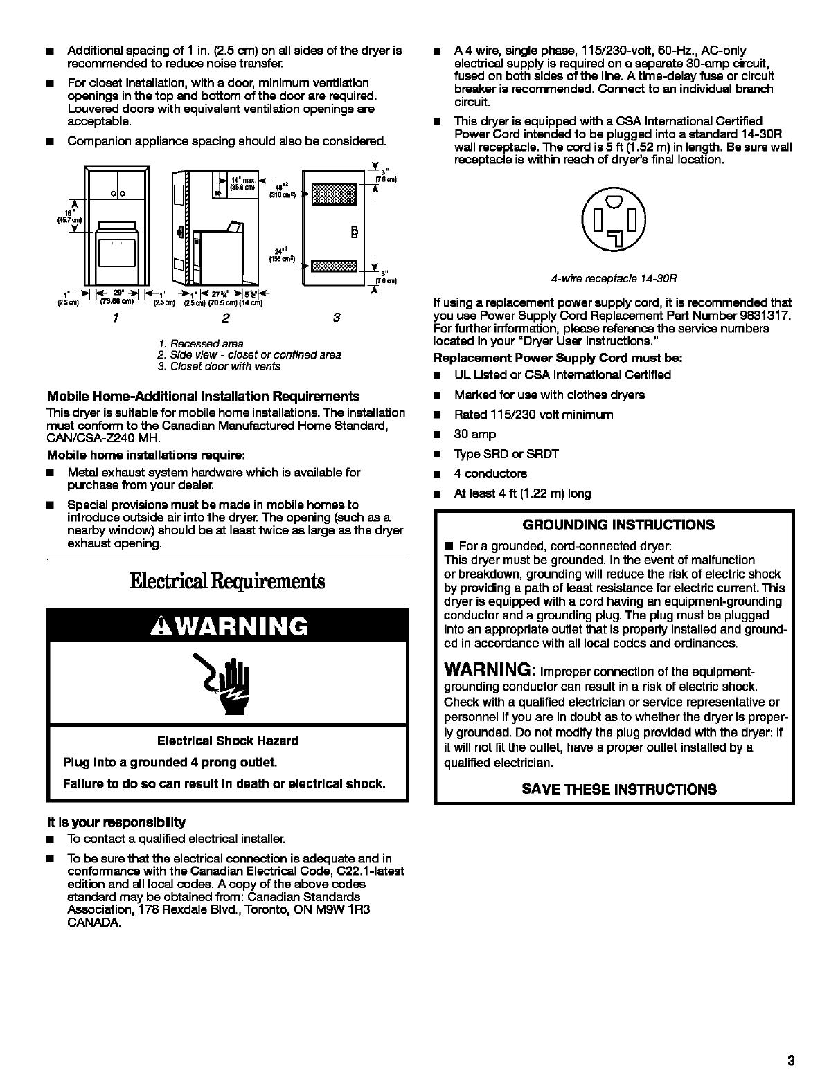
1.Recessed area
2. Side view - closet or confined area
3. Closet door with vents
Mobile Home-Additional Installation Requirements
This dryer issuitable for mobile home installations.The installation
must conform to the Canadian Manufactured Home Standard,
CAN/CSA-Z240 MH.
Mobile home installations require:
• Metal exhaust system hardware which is available for
purchase from your dealer.
Special pmvialons must be made in mobile homes to
introduce outside air into the dryeE The opening (such as a
nearby window) should be st least twice as large as the dryer
exhaust opening.
FAeetri qulrements
Electrical Shock Hazard
Plug Into a grounded 4 prong outlet.
Failure to do so can result In death or electrical shock.
It isyour responsibility
• Tocontacta qualifiedelectricalinstaller,
• To be sure that the electrical connection is adequate and in
conformance with the Canadian Electrical Code, C22.1-1atest
edition and all local codes. A copy ofthe above codes
standard may be obtained from: Canadian Standards
Association, 178 Rexdals Blvd., Toronto, ON Mgw 1R3
CANADA.
• A 4 wire, single phase, 115/230-volt, 60-Hz., AC-only
electrical supply is required on a separate 30-amp circuit,
fused on both sides of the line. A time-delay fuse or circuit
breaker is recommended. Connect to an individual branch
circuit.
• This dryer is equipped with a CSA International Certified
Power Cord intended to be plugged intoa standard 14-30R
wall receptacle. The cord is 5 ft (1.52 m) in length. Be sure wall
receptacle is within reach of dryer's final location.
©
4-wire receptacle14-30R
If usinga replacement power supply cord, it is recommended that
you use Power Supply Cord Replacement Part Number 9831317.
Forfurther information, please reference the service numbers
located in your "Dryer User Instructions."
Replacement Power Supply Cord must be:
• UL Listed or CSA International Certified
• Marked for use with clothes dryers
• Rated 115/230 volt minimum
• 30 amp
• Type SRD or SRDT
• 4 conductors
• At least 4 ft (1.22 m) long
GROUNDING INSTRUCTIONS
• For a grounded, cord-connected dryer:
This dryer must be grounded. In the event of malfunction
or breakdown, grounding will reduce the risk of electric shock
by providing a path of least resistance for electric current. This
dryer is equipped with a cord having an equipment-grounding
conductor and a grounding plug. The plug must be plugged
into an appropriate outlet that is properly installed and ground-
ed in accordance with all local codes and ordinances.
WARNING: Improper connection or the equipment-
grounding conductor can result in a risk ofelectric shock.
Check with a qualified electrician or service representative or
personnel ir you are in doubt as to whether the dryer is proper-
ly grounded. Do not modify the plug provided with the dryer: if
it will not fitthe outlet, have a proper outlet installed by a
qualified electrician.
SAVE THESE INSTRUCTIONS