Metra 99-6520B User manual

Category
Car kits
Type
User manual

Metra 99-6520B is a dash kit that allows you to install an aftermarket radio in your Dodge Journey 2011 or newer. It includes a radio trim panel, radio brackets, A/C button housing, pocket, and console bracket, as well as all necessary hardware. The kit is designed to retain the factory 4.3" screen and provides ISO DIN and DDIN radio provisions.

Metra 99-6520B is a dash kit that allows you to install an aftermarket radio in your Dodge Journey 2011 or newer. It includes a radio trim panel, radio brackets, A/C button housing, pocket, and console bracket, as well as all necessary hardware. The kit is designed to retain the factory 4.3" screen and provides ISO DIN and DDIN radio provisions.

APPLICATIONS
METRA. The World’s best kits.
metraonline.com1-800-221-0932
© COPYRIGHT 2014 METRA ELECTRONICS CORPORATION
REV. 9/16/2014 INST99-6520B
CAUTION: Metra recommends disconnecting the
negative battery terminal before beginning any
installation. All accessories, switches, and especially
air bag indicator lights must be plugged in before
reconnecting the battery or cycling the ignition.
NOTE: Refer to the instructions included with the
aftermarket radio.
INSTALLATION INSTRUCTIONS FOR PART 99-6520B
• ISO DIN radio provision with pocket
• ISO DDIN radio provision
• Included interface retains factory 4.3” screen
Painted matte black to match factory finish
A) Radio trim panel • B) Radio brackets • C) A/C button housing • D) Pocket • E) Console bracket
• F) (6) #8 x 3/8” Phillips pan-head screws • G) (2) White plastic panel clips • Axxess interface and harness (not shown)
KIT FEATURES
KIT COMPONENTS
WIRING & ANTENNA CONNECTIONS (sold separately)
Wiring Harness: • Interface and harnesses included
Antenna Adapter: • 40-EU10 Multi-app antenna adapter
• Panel removal tool • Phillips screwdriver
• Socket Wrench • Torx Screwdriver
TOOLS REQUIRED
Dodge Journey 2011-up
(Models with 4.3” screen)
99-6520B
A
B C D E
G
Dash Disassembly
Dodge Journey 2011-up ...................................2-3
Kit Assembly
ISO DIN radio provision with pocket ...................4-5
Double DIN radio provision ................................4-5
Axxess interface installation ..............................6-9
Table of Contents
F
99-6520B
2
Dash Disassembly
1. Unclip and remove the trim panel
along the top of the glove box over
to the passenger side a/c vent.
(Figure A)
2. Unclip and remove the small trim
panel to the left of the hazard
button. (Figure A)
3. Remove (2) Phillips screws
securing the climate/radio panel
then unclip and remove the panel.
(Figure B)
4. Remove (4) Torx screws securing
the radio chassis. (Figure C)
Continued on next page
(Figure A)
(Figure C)
(Figure B)
99-6520B
3
Dash Disassembly
5. Pull up on shift knob to remove
(Figure D).
6. Unclip and remove the shifter trim
panel including the cup holders
from the top of the center console.
(Figure E)
(Figure D) (Figure F)
(Figure E)
7. Push down and then pull back and
out on the pocket in the front of
the console. Tip: You may need
to pull the console side panels
outward at the same time as
pulling out on pocket. (Figure F)
8. Remove the (2) metal panel clips
on the front side of the pocket and
save for kit assembly.
Continue to kit assembly
99-6520B
Kit Assembly
4
1. Attach the console bracket to the
back of the A/C button housing
using (4) of the provided #8 x 3/8”
Phillips screws. Figure A
2. Install the (2) metal panel clips
saved from the pocket disassembly
onto the console bracket Figure A
3. Secure the A/C button housing into
the pocket space in the front of the
center console. Figure B
4. Attach the provided clips to the
radio trim panel. Figure C
(Figure A)
(Figure B)
(Figure C)
99-6520B
Kit Assembly
5
ISO DIN radio provision with pocket
1. Mount the pocket to the radio
brackets with (2) #8 x 3/8” Phillips
screws supplied. Note – Pins on
brackets will align with front
mounting hole of pocket.
Figure A
2. Slide the aftermarket radio into the
radio bracket/pocket assembly and
secure with the screws supplied
with the radio. Figure B
3. Locate the factory wiring harness
and antenna plug in the dash.
Refer to the Axxess Interface
Wiring section of this manual.
4. Mount the new radio/pocket
assembly into the dash and
reassemble dash in reverse order
of disassembly using the
99-6520B radio trim panel.
Double DIN radio provision
1. Break the small locating pin from
the inside surface of each bracket.
Figure A
2. Mount the DDIN radio to the radio
brackets using the screws supplied
with the radio. Figure B
3. Locate the factory wiring harness
and antenna plug in the dash.
Refer to the Axxess Interface
Wiring section of this manual.
4. Mount the new radio assembly into
the dash and reassemble dash in
reverse order of disassembly using
the 99-6520B radio trim panel.
(Figure A) (Figure A)
(Figure B)
(Figure B)
Remove pin
99-6520B
6
Provides accessory (12-volt 10-amp)
Retains R.A.P. (retained accessory power)
Used in non-amplified systems
Provides NAV outputs (parking brake, reverse and V.S.S.)
Prewired ASWC-1 harness included (ASWC-1 sold separately)
High level speaker input
Micro “B” USB updatable
Retains balance and fade
Ability to add aftermarket backup camera and additional video input
Retains OE screen
FEATURES
• Cutting tool • Crimping tool • Tape
• Connectors (example: butt-connectors, bell caps, etc.)
TOOLS REQUIRED
• Interface • 16-pin harness with stripped leads
• 18-pin harness to 22-pin Chrysler harness with stripped leads
• 40-pin climate extension cable
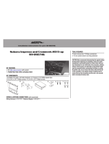
INTERFACE COMPONENTS
From the 16-pin harness to the aftermarket radio:
Connect the (2) Red wires to the ignition wire.
Connect the Orange/White wire to the illumination wire. If the aftermarket
radio has does not have an illumination wire, tape off the Orange/White wire.
Connect the Blue/White wire to the radio’s amp turn on wire.
Tape up and disregard the Brown wire, it will not be used in this application.
The following wires are for the multimedia aftermarket radios that have
navigation/video built in.
Connect the Light Green wire to the parking brake wire.
Connect the Blue/Pink wire to the VSS or speed sense wire.
Connect the Green/Purple wire to the reverse wire.
Plug the 16-pin harness into the interface.
Note: The following wires on the 16-pin harness are not used in this application.
Purple • Purple/Black • Green • Green/Black • White • White/Black • Gray • Gray/Black
Connections to be madeAxxess Interface Installation
99-6520B
7
From the 18-pin harness:
Connect the Yellow RCA labeled (1) to either a backup camera
(sold separately), or a video source.
Connect the Yellow RCA labeled (2) to either a backup camera
(sold separately), or a video source.
Note: It does not matter what RCA you use as they are programmable.
Plug the 18-pin harness into the interface.
Note: The following wires on the 18 pin harness are not used in this application.
Purple • Purple/Black • Green • Green/Black
Connections to be made
From the 22-pin harness to the aftermarket radio:
Connect the Yellow wire to the battery or memory wire.
Connect the Black wire to the ground wire.
Connect the White wire to the left front positive speaker output.
Connect the White/Black wire to the left front negative speaker output.
Connect the Gray wire to the right front positive speaker output.
Connect the Gray/Black wire to the right front negative speaker output.
Connect the Green wire to the left rear positive speaker output.
Connect the Green/Black wire to the left rear negative speaker output.
Connect the Purple wire to the right rear positive speaker output.
Connect the Purple/Black wire to the right rear negative speaker output.
Plug the 22-pin harness into the interface.
From the 12-pin harness to the aftermarket radio:
The 12-pin harness is to be used in conjunction with the optional ASWC-1
(not included) to retain steering wheel controls. If the ASWC-1 is not being used,
disregard this harness. If it will be used, please refer to the ASWC-1
instructions for programming.
Note: The white 40-pin harness from the factory must be connected to
the 99-6520B for the climate to function. We have included a 40-pin
extension cable to ease in installation.
99-6520B
Screen operation
1. Radio button – Show the current time
2. Player buttonToggles between Video 1 and Video 2 when input is activated
3. Climate buttonTakes you to the climate screen
4. Setting buttonTakes you to the setting screen
5. More button – Shows the outside temperature and current time
6. Screen OffTurns the display off
1
2
3
4
5
6
8
With all connections completed to the aftermarket radio, plug the 22-pin
harness into the vehicles wiring harness.
Reconnect the negative battery terminal.
Cycle the key, by turning the ignition on for 30 seconds. Then off and on again
to test the radio.
Turn the ignition on if not already, and then turn the radio on to verify that the
radio works. Check balance and fader controls for proper operation.
To adjust the overall volume of your audio system, rotate the potentiometer
which is located on the 16-pin side of the interface clockwise. (this is only done
if the vehicle is amplified).
Testing the Interface
Installing the Interface
99-6520B
9
Video option screen
2. From here select Video 1 or
Video 2. Once in the screen you
can select to make each video
input an AUX input, Backup
Camera input, or Not Used.
Note: The Backup camera input is
controlled by data and will activate
when you put the vehicle in reverse.
Note: The AUX video is controlled
by data and will only work when the
vehicle is in park.
1. Once in the setting screen
scroll down until you see the
Customize button. Tap the screen
and it will take you to the video
option screen.
3. After you have made your section tap the “Done button located on the upper
left hand corner of the screen to exit.
Pressing the About button will
display the current version number
and vehicles VIN number.
METRA. The World’s best kits.
metraonline.com1-800-221-0932
© COPYRIGHT 2014 METRA ELECTRONICS CORPORATION
REV. 9/16/2014 INST99-6520B
KNOWLEDGE IS POWER
Enhance your installation and fabrication skills by
enrolling in the most recognized and respected
mobile electronics school in our industry.
Log onto www.installerinstitute.com or call
800-354-6782 for more information and take steps
toward a better tomorrow.
Metra recommends MECP
certified technicians
INSTALLATION INSTRUCTIONS FOR PART 99-6520B
INSTRUCCIONES DE INSTALACIÓN PARA LA PIEZA 99-6520B
METRA. The World’s best kits.
metraonline.com1-800-221-0932
© COPYRIGHT 2014 METRA ELECTRONICS CORPORATION
RREV. 9/16/2014 INST99-6520B
KNOWLEDGE IS POWER
Enhance your installation and fabrication skills by
enrolling in the most recognized and respected
mobile electronics school in our industry.
Log onto www.installerinstitute.com or call
800-354-6782 for more information and take steps
toward a better tomorrow.
Metra recomienda técnicos
con certificación del Programa
de Certificación en Electrónica
Móvil (Mobile Electronics
Certification Program, MECP).
EL CONOCIMIENTO ES PODER
Mejore sus habilidades de instalación y fabricación
inscribiéndose en la escuela de dispositivos electrónicos
móviles más reconocida y respetada de nuestra industria.
Regístrese en www.installerinstitute.com o llame al
800-354-6782 para obtener más información y avance
hacia un futuro mejor.
  • Page 1 1
  • Page 2 2
  • Page 3 3
  • Page 4 4
  • Page 5 5
  • Page 6 6
  • Page 7 7
  • Page 8 8
  • Page 9 9
  • Page 10 10
  • Page 11 11
  • Page 12 12
  • Page 13 13
  • Page 14 14
  • Page 15 15
  • Page 16 16
  • Page 17 17
  • Page 18 18
  • Page 19 19
  • Page 20 20
  • Page 21 21
  • Page 22 22
  • Page 23 23
  • Page 24 24

Metra 99-6520B User manual

Category
Car kits
Type
User manual

Metra 99-6520B is a dash kit that allows you to install an aftermarket radio in your Dodge Journey 2011 or newer. It includes a radio trim panel, radio brackets, A/C button housing, pocket, and console bracket, as well as all necessary hardware. The kit is designed to retain the factory 4.3" screen and provides ISO DIN and DDIN radio provisions.

Ask a question and I''ll find the answer in the document

Finding information in a document is now easier with AI

in other languages