Kenwood DNX7020EX Owner's manual
- Category
- Car video systems
- Type
- Owner's manual
This manual is also suitable for

GPS NAVIGATION SYSTEM
SYSTÈME DE NAVIGATION GPS
SISTEMA DE NAVEGACIÓN GPS
DNX SERIES
DNX7160 DNX7020EX
INSTALLATION MANUAL
MANUEL D'INSTALLATION
MANUAL DE INSTALACIÓN
© B54-4776-00/00 (KW/K2W)

2
DNX SERIES
Installation Procedure
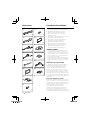
1
..........1
2
..........1
3
..........1
4
..........1
5
..........2
6
..........1
7
..........1
8
..........6
9
..........6
0
..........1
!
..........1
@
..........1
#
..........1
$
..........1
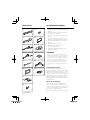
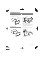
Accessories
1. To prevent a short circuit, remove the key
from the ignition and disconnect the -
battery.
2. Make the proper input and output wire
connections for each unit.
3. Connect the speaker wires of the wiring
harness.
4. Connect the wiring harness wires in the
following order: ground, battery, ignition.
5. Connect the wiring harness connector to
the unit.
6. Install the unit in your car.
7. Reconnect the - battery.
8. Press the reset button.
9. Perform the Initial Setup. (Refer to the
Instruction Manual.)
2WARNING
• If you connect the ignition wire (red) and the
battery wire (yellow) to the car chassis (ground),
you may cause a short circuit, that in turn may
start a fire. Always connect those wires to the
power source running through the fuse box.
• Do not cut out the fuse from the ignition wire
(red) and the battery wire (yellow). The power
supply must be connected to the wires via the
fuse.
Acquiring GPS Signals
The first time you turn on this unit, you
must wait while the system acquires satellite
signals for the first time. This process could
take up to several minutes. Make sure your
vehicle is outdoors in an open area away from
tall buildings and trees for fastest acquisition.
After the system acquires satellites for the
first time, it will acquire satellites quickly each
time thereafter.
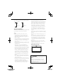
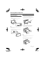
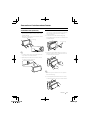
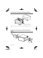
About the Front Panel
When removing the product from the
box or installing it, the front panel may be
positioned at the angle shown in (Fig. 1). This
is due to the characteristics of mechanism
the product is equipped with.
When the product is first powered on works

English
3
properly, the front panel will automatically
move into the position (initial setting angle)
shown in (Fig. 2).
(Fig. 1)
(Fig. 2)
After the Installation
After the installation, perform the Initial Setup
by referring to the instruction manual.
¤
• Mounting and wiring this product requires
skills and experience. For best safety, leave the
mounting and wiring work to professionals.
• Make sure to ground the unit to a negative 12V
DC power supply.
• Do not install the unit in a spot exposed to direct
sunlight or excessive heat or humidity. Also avoid
places with too much dust or the possibility of
water splashing.
• Do not use your own screws. Use only the screws
provided. If you use the wrong screws, you could
damage the unit.
• If the power is not turned ON (“PROTECT” is
displayed), the speaker wire may have a short-
circuit or touched the chassis of the vehicle and
the protection function may have been activated.
Therefore, the speaker wire should be checked.
• If your car’s ignition does not have an ACC
position, connect the ignition wires to a power
source that can be turned on and off with the
ignition key. If you connect the ignition wire to
a power source with a constant voltage supply,
such as with battery wires, the battery may be
drained.
• If the console has a lid, make sure to install the
unit so that the faceplate will not hit the lid when
closing and opening.
• If the fuse blows, first make sure the wires aren’t
touching to cause a short circuit, then replace the
old fuse with one with the same rating.
• Insulate unconnected wires with vinyl tape or
other similar material. To prevent a short circuit,
do not remove the caps on the ends of the
unconnected wires or the terminals.
• Connect the speaker wires correctly to the
terminals to which they correspond. The unit may
be damaged or fail to work if you share the -
wires or ground them to any metal part in the car.
• When only two speakers are being connected
to the system, connect the connectors either to
both the front output terminals or to both the
rear output terminals (do not mix front and rear).
For example, if you connect the + connector
of the left speaker to a front output terminal, do
not connect the - connector to a rear output
terminal.
• After the unit is installed, check whether the brake
lamps, blinkers, wipers, etc. on the car are working
properly.
• Mount the unit so that the mounting angle is 30°
or less.
• This unit has the cooling fan (page 5) to decrease
the internal temperature. Do not mount the unit
in a place where the cooling fan of the unit are
blocked. Blocking these openings will inhibit the
cooling of the internal temperature and result in
malfunction.
• Do not press hard on the panel surface when
installing the unit to the vehicle. Otherwise scars,
damage, or failure may result.
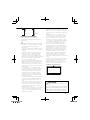
• Reception may drop if there are metal objects
near the Bluetooth antenna.
Bluetooth antenna unit
¤ CAUTION
Install this unit in the console of your
vehicle.
Do not touch the metal part of this unit
during and shortly after the use of the
unit. Metal part such as the heat sink and
enclosure become hot.

4
DNX SERIES
A
PRK SW
A
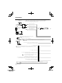
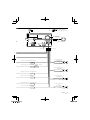
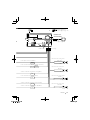
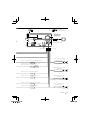
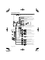
Connection
If you connect the ignition wire (red) and the battery wire (yellow)
to the car chassis (ground), you may cause a short circuit, that in
turn may start a fire. Always connect those wires to the power
source running through the fuse box.
Antenna Cord
FM/AM antenna input
For best safety, be sure to connect the parking sensor.
Parking sensor wire (Light Green)
Connect to the vehicle's parking brake
detection switch harness.
Battery wire (Yellow)
Ground wire (Black) -
(To car chassis)
Ignition wire (Red)
To steering remote
If no connections are made, do not let the cable come out from the tab.
Connect to the terminal that is grounded when either
the telephone rings or during conversation.
Depending on what antenna you are using,
connect either to the control terminal of the motor antenna, or to the
power terminal for the booster amplifier of the film-type antenna.
When using the optional power amplifier,
connect to its power control terminal.
To car light control switch
Connect to vehicle's reverse lamp harness when
using the optional rear view camera.
Ignition key
switch
ACC
Car fuse box
(Main fuse)
Battery
Car fuse box
To connect the Kenwood navigation system,
consult your navigation manual.
To use the steering wheel remote control feature, you need to an
exclusive remote adapter (not supplied) matched to your car is
required.
⁄
⁄
⁄
⁄
¤

English
5
ANT. CONT
P.CONT
REVERSE
MUTE
+
+
+
+
ILLUMI
REMOTE CONT
STEERING WHEEL
REMOTE INPUT
To front left speaker
To front right speaker
To rear left speaker
To rear right speaker
White/Black
White
Gray/Black
Gray
Green/Black
Green
Purple
Purple/Black
Accessory 1
Cooling fan
FUSE ( 15A )
GPS Antenna
(Accessory !) (see page 8)
Steering remote control input (Light Blue/Yellow)
Mute control wire (Brown)
Motorized antenna control wire (Blue)
Power control wire (Blue/White)
Dimmer control wire (Orange/White)
Reverse sensor wire (Purple/White)
Bluetooth Microphone
(Accessory #) (see page 8)

6
DNX SERIES
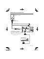
System Connection
RELAY 2
RELAY 1
CAMERA
REAR VIEW
AV IN
AV OUT
FRONT
REAR
WOOFER
SUB
Front Preout
• Audio left output (White)
• Audio right output (Red)
Rear Preout
• Audio left output (White)
• Audio right output (Red)
Subwoofer Preout
• Audio left output (White)
• Audio right output (Red)
Rear View Camera Input
• Visual input (Yellow)
Audio/Visual Input
• Visual input (Yellow)
• Audio left input (White)
• Audio right input (Red)
Audio/Visual Output
• Visual output (Yellow)
• Audio left output (White)
• Audio right output (Red)
USB device or iPod (commercially available)
Visual input (iPod/AV Input 2 switchable)
Resistance-free mini plug (3.5φ)
Audio input (iPod/AV Input 2 switchable)
Resistance-free stereo type mini plug (3.5φ)
USB terminal
When connecting the TMC Tuner GTM10
(optional accessory), put the cable
clamper (accessory $) to the back of
this unit first, and then wire the cable
through the clamper.
To TMC Tuner GTM10
(optional accessory)
Accessory $
⁄
To Relay Box
To Camera
control terminal
Accessory 2
Accessory 3
Accessory 4
(Blue/Red)
(Blue/Red)
(Green/White)
(Green/Red)

English
7
Optional Accessory Connection
TV ANTENNA INPUT
TO MONITOR UNIT
KCA-iP301V
(Optional Accessory)
iPod
(commercially available)
Audio Output (Black)
Visual Output (Yellow)
To SIRIUS Satellite Radio tuner/
XM Satellite Radio tuner/ HD Radio tuner
(Optional Accessory)
Conversion adapter (optional accessory)
may be necessary for connection of
optional accessory.
Contact your Kenwood dealer for details.
USB terminal USB terminal
TV Tuner
(Optional Accessory)
Connection cable
(Included in the TV tuner)
⁄

8
DNX SERIES
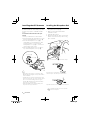
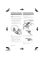
Installing the GPS Antenna
GPS antenna is installed inside of the car. It
should be installed as horizontally as possible
to allow easy reception of the GPS satellite
signals.
To mount the GPS antenna inside your
vehicle:
1. Clean your dashboard or other surface.
2. Peel the backing off of the adhesive on the
bottom of the metal plate (accessory @).
3. Press the metal plate (accessory @)
down firmly on your dashboard or other
mounting surface. You can bend the
metal plate (accessory @) to conform to a
curved surface, if necessary.
4. Place the GPS antenna (accessory !) on
top of the metal plate (accessory @).
Accessory !
Accessory @
¤
• Depending on the type of car, reception of the
GPS satellite signals might not be possible with an
inside installation.
• The GPS antenna should be installed at a position
that is spaced at least 12 inch (30 cm) from cellular
phone or other transmitting antennas. Signals
from the GPS satellite may be interfered with by
these types of communication.
• Painting the GPS antenna with (metallic) paint
may cause a drop in performance.
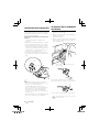
1. Check the installation position of the
microphone (accessory #).
2. Remove oil and other dirt from the
installation surface.
3. Install the microphone.
4. Wire the microphone cable up to the unit
with it secured at several positions using
tape or the like.
Fix a cable with a commercial item of tape.
Peel the release coated paper of double-face
adhesive tape to fix on the place shown above.
Adjust the direction of the microphone to the driver.
Accessory #
Installing the Microphone Unit
Install the microphone as far as possible
from the cell-phone.
⁄

English
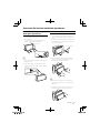
9
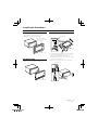
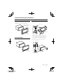
For Toyota/Scion
1. Cut out accessory 6 as illustrated.
Cutting line
Accessory 6
2. Fold double-sided adhesive (accessory 7)
along the slit and attach it to accessory
6 cut-out against the center rib as
illustrated. Use 2 pieces of accessory 7 for
1 accessory 6 cut-out.
3. Attach accessory 6 cut-out to the unit.
Accessory 7
For General Motors
1. Cut out accessory 6 to meet the shape of
the opening of the center console.
2. Attach accessory 6 to the unit.
Accessory 6
Cut out to meet the
shape of the opening
in the vehicle.
For Volkswagen
1. Attach accessory 0 to the unit.
Accessory 0
Installing the Escutcheon

10
DNX SERIES
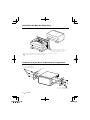
Installation for Monitor/Player Unit
⁄
Make sure that the unit is installed securely in place. If the unit is unstable,
it may malfunction (eg, the sound may skip).
Bend the tabs of the mounting
sleeve with a screwdriver or similar
utensil and attach it in place.
Car Bracket
Accessory 8 (M5x6mm)
or Accessory 9 (M5x7mm)
Accessory 8 (M5x6mm)
or Accessory 9 (M5x7mm)
Installation on Toyota, Nissan or Mitsubishi Car using Brackets

English
11
Removing the Hard Rubber
Frame (escutcheon)
1. Engage the catch pins on the removal tool
5 and remove the two locks on the lower
level.
Lower the frame and pull it forward as
shown in the figure.
Accessory 5
Lock
Catch
⁄
• The frame can be removed from the top side in
the same manner.
2. When the lower level is removed, remove
the upper two locations.
Removing the Unit
1. Remove the hard rubber frame by referring
to the removal procedure in the section
<Removing the Hard Rubber Frame>.
2. Insert the two removal tools 5 deeply into
the slots on each side, as shown.
Accessory 5
3. Lower the removal tool toward the
bottom, and pull out the unit halfway
while pressing towards the inside.
⁄
• Be careful to avoid injury from the catch pins on
the removal tool.
4. Pull the unit all the way out with your
hands, being careful not to drop it.
Removing Monitor/Player Unit
Page is loading ...
Page is loading ...
Page is loading ...
Page is loading ...
Page is loading ...
Page is loading ...
Page is loading ...
Page is loading ...
Page is loading ...
Page is loading ...
Page is loading ...
Page is loading ...
Page is loading ...
Page is loading ...
Page is loading ...
Page is loading ...
Page is loading ...
Page is loading ...
Page is loading ...
Page is loading ...
Page is loading ...
-
 1
1
-
 2
2
-
 3
3
-
 4
4
-
 5
5
-
 6
6
-
 7
7
-
 8
8
-
 9
9
-
 10
10
-
 11
11
-
 12
12
-
 13
13
-
 14
14
-
 15
15
-
 16
16
-
 17
17
-
 18
18
-
 19
19
-
 20
20
-
 21
21
-
 22
22
-
 23
23
-
 24
24
-
 25
25
-
 26
26
-
 27
27
-
 28
28
-
 29
29
-
 30
30
-
 31
31
-
 32
32


Kenwood DNX7020EX Owner's manual
- Category
- Car video systems
- Type
- Owner's manual
- This manual is also suitable for
Ask a question and I''ll find the answer in the document
Finding information in a document is now easier with AI
in other languages
Related papers
-
Kenwood DDX8046BT User manual
-
Kenwood DNX 7260 BT Installation guide
-
-
-
-
-
Kenwood DNX 9260 BT User manual
-
-
-
Other documents
-
JVC KW-NT500HDT User manual
-
-
Pioneer DEH-P4700MP User manual
-
JVC KW-NT1 User manual
-
JVC KD-AVX33 Installation guide
-
-
Clarion CX501 Installation guide
-
-
-