PREPARING THE INSTALLATION LOCATION
NOTE
MOUNT HOOD SO THAT BOTTOM OF HOOD IS 18”-24” ABOVE COOKING SURFACE.
TOP FRONT EDGE OF HOOD SHOULD BE FLUSH WITH FRONT OF CABINET FRAME.
IF DISTANCE BETWEEN WALL AND FRONT OF CABINET FRAME IS MORE THAN 12”
THERE WILL BE A SPACE BETWEEN BACK OF HOOD AND WALL. THIS IS NORMAL.
OMIT STEP 9 if range hood will be installed under cabinets with flush bottom.
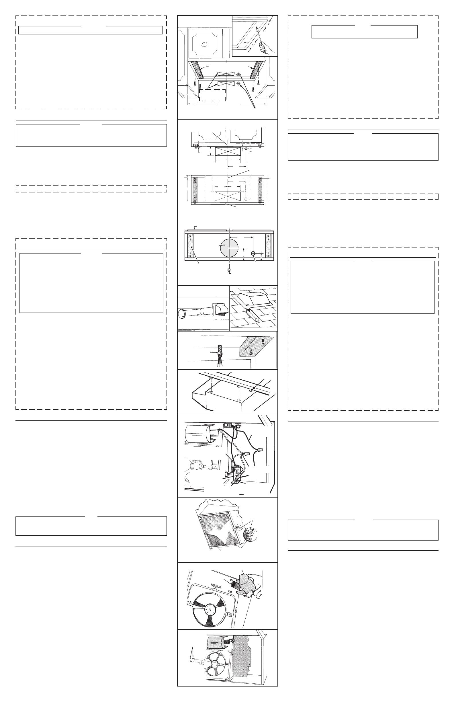
9. (For installation on recessed bottom cabinets only) Attach a wood filler strip at
each side of recessed area under cabinet. (Use two 1” x 2” strips cut to length.)
If recess is more than 1” use thicker strips. Attach strips with 1-1/4” screws about
3” from each end. See FIG. 7.
10. Measure and mark the following (FIGS. 7 & 8):
a) Electrical line opening
b) Duct opening
11. Drill four pilot holes in corners of marked duct opening as shown and cut opening
with saber saw or keyhole saw.
12. Use 1-1/4” drill bit to drill opening for electrical connection in wall or cabinet.
13. Hold hood up against cabinet bottom and trace keyhole slots onto cabinet bottom
of filler strips.
14. Screw the four supplied 7/8” wood screws for mounting the hood into the exact
center of the narrow end of the keyhole slots marked underneath the cabinet.
Allow 3/8” of the screws to project, so the hood can be fitted into place.
INSTALLING THE DUCTWORK
NOTE
THESE INSTRUCTIONS WILL FOLLOW THE PLANS MADE ON PAGE 2. START
AT THE EXTERIOR AND RUN THE DUCT BACK TO THE RANGE HOOD.
FOR BEST PERFORMANCE OF YOUR RANGE HOOD, USE THE SHORTEST
POSSIBLE DUCT RUN AND A MINIMUM NUMBER OF ELBOWS.
NEVER VENT A RANGE HOOD INTO AN ATTIC SPACE BECAUSE A BUILDUP
OF GREASE WILL BECOME A FIRE HAZARD.
USE ONLY METAL DUCTWORK (DO NOT USE PLASTIC DUCT). ASSEMBLE
SECURELY SO THAT IN CASE OF A GREASE FIRE ON THE RANGE, THE FIRE
WILL BE CONTAINED INSIDE METAL DUCT WORK.
IT IS A GOOD PRACTICE TO TAPE ALL DUCT CONNECTIONS, MAKING THEM
BOTH SECURE AND AIR TIGHT.
15. Follow appropriate directions below for type of duct work you are installing:
WALL CAPS (FIG. 9)
Use a saber saw to cut a hole slightly larger than duct so duct will line up easily
with hood. Install casing strips on outside walls finished in siding. Assemble the
duct work and tape all joints. Run duct work back to hood. Fasten wall cap to last
section of duct and nail or screw cap to wall. Seal all around flange on wall cap
with caulking compound. Make sure that enough duct runs into the room so that
the duct will overlap the damper/duct connector by 3/4” when the hood is installed.
ROOF CAPS
Cut hole in roof slightly larger than duct so duct will line up easily with hood. Trim
shingles around hole so that they will fit snugly around hood of cap when cap is
installed. Assemble the duct work and tape all joints. Run the duct work down to
hood. Trim duct parallel to roof pitch, leaving 3/4” of duct projecting above roof.
Seal all around duct with roof cement.
Install roof cap, inserting back edge of cap under shingles. Seal around cap with
roof cement and seal all nail heads and shingles which were cut or lifted.
Make sure that enough duct runs into the room so that the duct will overlap the
damper/duct connector by 3/4” when the hood is put into place.
USE AND CARE
SWITCHES
The fan and light are each controlled by a rocker switch. The light switch has two
positions, “ON” and “OFF”. The fan switch has three positions - “HIGH”, “LOW” and
“OFF”. ( “OFF” is the middle position.)
CLEANING
Finish Keep your range hood clean using a mild detergent suitable for painted surfaces.
Aluminum Filters should be cleaned frequently with a detergent solution to avoid grease
build up. They are also dishwasher safe.
FILTER REMOVAL
Remove filter by turning filter clip to the side and lifting filter out. In ducted version,
turn filter retaining clip to one side and place aluminum filter over embossed retaining
tabs on back of fan housing. Turn filter clip so that the low end of clip holds single
filter firmly in place. (FIG. 13)
In non-ducted version, place non-ducted filter (non-ducted filter to be purchase
separately, model 41F) over tabs on back of fan housing. Turn filter retaining clip so
that high end holds filter firmly in place. Make sure blue side of non-ducted filter is
next to fan blade.
NOTE: Make sure that arrows on filter retaining clip point toward back and front of hood.
LIGHT BULB REPLACEMENT
Light bulb (not supplied with hood) should be 75 watts maximum. The lens covering
bulb is removed by pressing the two extending tabs together until they release
from the retaining slots. (FIG. 14)
FAN ASSEMBLY REMOVAL
Be sure power is disconnected. Remove filters. Remove the two screws holding the
motor bracket to the range hood and unplug the fan assembly. Be careful not to allow
fan assembly to drop when the screws are removed. (FIG. 15).
INSTALLING THE RANGE HOOD
16. Bring electrical cable through access hole drilled in wall or bottom of cabinet.
Provide 6” wire leads and install proper connector for type of cable being used.
Remove lock nut from connector and let prepared cable project through cabinet
or wall opening so it is ready for installation into range hood. (FIG. 10)
17. Position hood in place so that:
a) Electrical line is routed through appropriate knockout opening. This step will have
to be accomplished while positioning hood. (FIG. 13)
b) Large part of keyhole mounting slots on hood fit onto hood mounting screws
projecting from bottom of cabinet. (FIG. 11)
c) Damper/duct connector slides into duct work in wall or cabinet.
18. Adjust hood so the front of hood is flush with cabinet front.
19. Tighten the four hood mounting screws securely.
20. Install locknut on electrical connector and tighten securely.
21. Make electrical connection using wire nuts to connect white wire to white, black
wire to black. Ground hood to prepared hole using green ground screw provided.
(FIG. 12)
22. Replace wiring box cover and screw. Make sure that all wiring is safely contained
inside.
NOTE
For Ductfree Installations Only:
Install both filters. Make sure that ductfree filter (purchase separately) is next to
fan assembly with blue side next to blade. Aluminum filter should be facing out.
FIG. 7
CUT STRIPS TO FIT
CORTE LAS TIRAS PARA
QUE QUEPAN
CENTER LINE
LINEA CENTRICA
WIDTH OF
RANGE HOOD
ANCHO DEL
EXTRACTOR
ELECTRICAL WIRING OPENING
ABERTURA PARA EL CABLEA-
DO ELECTRICO
DUCT OPENINGS
ABERTURA PARA
EL DUCTO
FIG. 8
FRONT OF CABINET
PARTE FRONTAL DEL
GABINETE
VERTICAL DUCTING AND WIRING
(Through Cabinet Bottom)
DUCTOS Y ALAMBRES PARA CONEXION VERTICAL
(A través de la parte inferior del gabinete)
CABINET BOTTOM
PARTE INFERIOR DEL
GABINETE
BACK WALL
PARED TRASERA
FIG. 9
WALL CAP
TAPA DE PARED
3/8”
3-7/8”
HORIZONTAL DUCTING AND
WIRING (Through Wall)
DUCTOS Y ALAMBRES PARA CONEXION
HORIZONTAL (A través de la pared)
5-1/4”
5-1/4”
7-1/2”
1/8”
3/4”
1-1/2”
1-1/2”
9”
10-5/8”
6-7/8”
7-1/2”
5-1/4”
5-1/4”
9-7/8”
9”
CABINET FRONT / FRENTE DEL GABINETE
CABINET BOTTOM
FONDO DEL GABINETE
7½"
2"
5"
WOOD SHIMS
(recessed-bottom cabinets only)
CUÑAS DE MADERA
(sólo gabinetes de fondo empotrado)
ELECTRICAL ACCESS HOLE
(in cabinet bottom)
ORIFICIO DE ACCESO PARA
LOS CABLES ELÉCTRICOS
(en el fondo del gabinete)
8" DIA. ACCESS HOLE
ORIFICIO DE ACCESO
8" DE DIÁ.
3-1/4” x 10” DUCT / DUCTO DE 3-1/4” x 10”
7” ROUND DUCT / DUCTO REDONDO DE 7”
CONNECTOR
CONECTOR
FIG. 12
FIG. 13
NON-DUCTED FILTER (SOLD SEPARATELY)
FILTRO QUE NO REQUIERE DUCTO
(VENDIDO SEPARADAMENTE)
ALUMINUM FILTER
FILTRO DE ALUMINIO
FILTER RETAINING CLIP
GRAMPA RETENTORA
DEL FILTRO
FIG. 14
LIGHT LENS
VIDRIO QUE CUBRE EL BOMBILLO
SOCKET
BOQUILLA
FIG. 15
SCREWS
TORNILLOS
ELECTRICAL LINE
LINEA ELECTRICA
FIG. 11
FIG. 10
BLACK WIRES
ALAMBRES NEGROS
STAR LOCKNUT
TUERCA TRABANTE EN
FORMA DE ESTRELLA
GREEN GROUND SCREW
TORNILLO VERDE PARA TIERRA
GROUND WIRE (BARE OR
GREEN WIRE)
ALAMBRE DE TIERRA
(ALAMBRE DESNUDO O
VERDE)
WHITE WIRES
ALAMBRES BLANCOS
GROUNDING BRACKET
SOSTEN PARA CONEC-
TAR A TIERRA
DUCTED INSTALLATION ONLY
NOTE
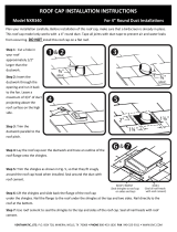
Louver cover must be installed as shown in Figure 3 to function in ducted mode.
6. Remove appropriate duct knockout on hood by inserting screwdriver into edge
of knockout and breaking tabs holding knockout to hood. You may have to tap
screwdriver with hammer to break tabs. Peel knockout back with pliers. (FIG.
5)
7. Fit damper/duct connector over opening and secure in place with black sheet
metal screws. (FIG. 6)
Hinge pins and damper/duct connector should be toward top of hood for ducting
through wall or toward back of hood for ducting through cabinet above hood.
Seal joint between damper/duct connector and hood with duct tape.
8. 7” round ducted discharge only: Re-install 7” round duct plate removed in Step
#2 under “PREPARING THE RANGE HOOD” section. For best performance,
line up the 7” round duct plate with the 7” round opening on hood. Mount
duct plate to hood with 2 screws from duct plate and 2 screws from 3¼” x 10”
damper. Install a 7” round damper (purchase separately). Damper flap must
open freely in direction of air flow (away from range hood).
INSTALANDO LOS DUCTOS
NOTESE
ESTAS INSTRUCCIONES SEGUIRÁN LOS PLANES HECHOS EN LA PÁGINA 2. COMIENCE EN LA
PARTE EXTERIOR Y TRAIGA EL DUCTO HACIA EL EXTRACTOR.
PARA EL MEJOR RENDIMIENTO DE SU EXTRACTOR, USE EL CAMINO MÁS CORTO DE DUCTO
Y UN MÍNIMO DE CODOS.
NUNCA DESCARGUE EL AIRE DEL EXTRACTOR EN EL ESPACIO DE LA BUHARDILLA PORQUE
UNA ACUMULACIÓN DE GRASA PODRÍA CAUSAR UN INCENDIO.
USE SOLAMENTE DUCTOS DE METAL (NO USE DUCTOS DE PLÁSTICO). ENSÁMBLELOS BIEN DE
MANERA QUE EN CASO DE QUE HUBIESE UN INCENDIO CAUSADO POR GRASA, EL INCENDIO
SE QUEDARÁ CONTENIDO DENTRO DE LOS DUCTOS DE METAL.
ES UNA BUENA PRÁCTICA EL PONER CINTA EN TODAS LAS CONEXIONES DEL DUCTO HACIÉN-
DOLOS NO SOLAMENTE SEGUROS SI NO TAMBIÉN A PRUEBA DE ESCAPE DE AIRE.
15. Siga las direcciones apropiadas abajo para el tipo de ductos que esté instalando:
CASQUETES DE PARED (FIG. 9)
Use una sierra sable para cortar un hueco ligeramente más grande que el diámetro del ducto de manera
que el ducto se alinee más fácilmente con el extractor. Instale tiras de sostén en las paredes exteriores
que estén acabadas con superficie exterior de madera, aluminio o vinilo. Ensamble los ductos y ponga
cinta en todas las uniones. Traiga los ductos de afuera hacia al extractor. Sujete el casquete de pared
a la última sección de ducto y clave el casquete a la pared. Selle alrededor de la ceja del casquete con
un compuesto para rellenar. Asegúrese que hay suficiente ducto que entra a la cocina de manera que
el ducto sobrepasará y entrará dentro el conector de regulador/ducto por lo menos por 3/4” cuando
esté el ducto instalado.
CASQUETES DEL TECHO
Corte un hueco en el techo más grande que el diámetro del ducto de manera que el ducto se alineará
más fácilmente con el extractor. Recorte el tejado (tablillas de tejado) alrededor de hueco de manera
que quepan apretadamente alrededor de casquete cuando éste instalado. Ensamble los ductos y ponga
cinta aislante en todas las uniones. Traiga el ducto hacia abajo, al extractor. Recorte el ducto paralelo a
la inclinación del techo, dejando 3/4” de ducto que se proyecte más arriba de techo. Selle la abertura
alrededor de ducto con cemento de techo.
Instale el casquete insertando el filo de atrás de la ceja del casquete debajo de las tablillas del tejado.
Selle alrededor del casquete con cemento de techo y selle todas las cabezas de clavos y tablillas que
fueron cortadas o levantadas.
Asegúrese que haya suficiente ducto que se proyecte dentro la cocina de manera que el ducto sobrepase
al conector de regulador/ducto por 3/4” cuando el extractor esté en su sitio.
10. Mida y marque lo siguiente (FIG. 7 & 8):
a) Abertura para la línea eléctrica
b) Abertura para el ducto
11. Perfore cuatro huecos pilotos en las esquinas ya marcadas de la abertura para el ducto como
se muestra y luego corte un abertura con un serrucho sable o un serrucho para cerradura.
12. Usese una broca de 1-1/4” para perforar una abertura para la conexión eléctrica en la pared
o gabinete.
13. Sostenga al extractor debajo de la parte inferior del gabinete y trace las ranuras en forma de
hueco de cerradura en la parte inferior del gabinete donde se instalarán las tiras de madera.
14. Atornille cuatro de los tornillos de madera de 7/8” para montar el extractor en el centro
exacto de la parte estrecha de la ranuras en forma de cerradura que se marcaron debajo del
gabinete. Permita que 3/8” de los tornillos queden afuera, para que luego pueda instalarse
al extractor en su sitio.
USO Y MANTENIMIENTO
LOS INTERRUPTORES
El abanico y el foco están controlados individualmente por un interruptor balancín. El interruptor
del foco tiene dos posiciones, ENCENDIDO (“ON”) y APAGADO (“OFF”). El interruptor del abanico
tiene tres posiciones - ALTA (“HIGH”), BAJA (“LOW”) y APAGADO (“OFF”). (El interruptor para
APAGADO está en la posición de en medio.)
LIMPIEZA
Acabado. Mantenga el extractor limpio usando un detergente suave apropiado para superficies
pintadas.
Filtros aluminio. Deberían limpiarse frecuentemente en una solución de detergente para evitar la
acumulación de grasa. Estos pueden ser lavados en la lavadora de platos.
QUITANDO EL FILTRO
Retire el filtro girando el clip del filtro hacia un lado y sacando el filtro. En la versión con ductos,
gire el clip que retiene el clip hacia un lado y coloque el filtro de aluminio sobre las pestañas de
retención en relieve en la parte posterior del alojamiento del ventilador. Gire el clip del filtro de
modo que el extremo inferior del clip sujete firmemente el filtro individual en su lugar. (Figura 13)
En la versión sin conducto, coloque el filtro sin conducto (filtro sin conducto que se comprará
por separado, modelo 41F) sobre las pestañas en la parte posterior de la carcasa del ventilador.
Gire el clip que retiene el filtro de modo que el extremo superior sostenga el filtro firmemente en
su lugar. Asegúrese de que el lado azul del filtro sin conducto esté al lado del aspa del ventilador.
NOTA: Asegúrese de que las flechas en el clip que retiene el clip apunten hacia la parte posterior
y delantera de la campana.
REEMPLAZO DEL BOMBILLO DE LUZ
El bombillo de luz (que no viene con el extractor) debería de ser de un máximo de 75 vatios. El vidrio
lente que cubre el bombillo se quita pellizcado los dos sostenes que se extienden, hasta que se salen de
sus ranuras retentoras. (FIG. 14)
COMO QUITAR EL ENSAMBLAJE DEL VENTILADOR
Asegúrese que la potencia eléctrica esté desconectada. Quite los filtros. Quite los dos tornillos que
sostienen el sostén del motor al extractor y desenchufe el ensamblaje de ventilador. Tenga cuidado
que no permita que el ensamblaje del ventilador se caiga cuando se quiten los tornillos. (FIG. 15)
INSTALACION CON DUCTO SOLAMENTE
NOTA
La cubierta de las rejillas se debe instalar como se
muestra en la figura 3 para que funcione con el conducto.
6. Quite la placa de quitar golpeando en el extractor insertando un destornillador en el filo y
rompiendo las conexiones que lo sostienen al extractor. Es posible que tenga que golpear el
destornillador con un martillo para romper estas uniones. Pele la tapa de quitar golpeando
hacia atrás con una tenaza. (FIG. 5)
7. Junte el conector del regulador/ducto sobre la abertura y sujételo en su sitio con tornillos
negros de metal para lámina. (FIG. 6)
Los pasadores de bisagra y el conector del regulador/ducto deben de estar hacia la parte
de arriba del extractor para pasar el ducto a través de la pared o hacia la parte de atrás
del extractor para pasar el ducto a través de gabinete encima del extractor. Selle la unión
entre el conector regulador/ducto con cinta de ducto.
8. Sólo para descargas con conducto redondo de 7”: Vuelva a instalar la placa del conducto
redondo de 7” que quitó en el paso 2 de la sección “PREPARANDO EL EXTRACTOR.” Para
obtener un mejor rendimiento, alinee la placa del conducto redondo de 17.8 cm (7”)
con la abertura redonda de 17.8 cm (7”) de la campana. Monte la placa del conducto a
la campana con dos tornillos desde la placa del conducto y con dos tornillos desde el tiro
de 8.3 x 25.4 cm (3 ¼” x 10”). Instale un regulador de tiro redondo de 7” (se compra por
separado). La aleta del regulador se debe abrir libremente en dirección del flujo de aire
(en sentido contrario a la campana de la estufa).
PREPARANDO LA UBICACION DE LA INSTALACION
NOTA
MONTE EL EXTRACTOR DE MANERA QUE LA PARTE INFERIOR ESTÉ 18”-24” ENCIMA DE
LA SUPERFICIE DE LA COCINA. LA PARTE SUPERIOR DEL FRENTE DEL EXTRACTOR DEBE
DE ESTAR A RAS CON EL FRENTE DEL ARMAZÓN DEL GABINETE.
SI LA DISTANCIA ENTRE LA PARED Y LA PARTE FRONTAL DEL ARMAZÓN DEL GABINETE ES
MÁS DE 12” HABRÁ UN ESPACIO ENTRE LA PARTE DE ATRÁS DEL EXTRACTOR Y LA PARED.
ESTO ES NORMAL.
OMITA PASO 7 si el extractor estará instalado debajo de un gabinete con la parte inferior plana.
9. (Para instalación en gabinetes ahuecados solamente) Sujete una tira de madera a cada lado de
la parte inferior ahuecada debajo del gabinete. (Use dos tiras de madera de 1” x 2” cortadas
al largo necesario.) Si el ahuecamiento es más de 1” use tiras más gruesas. Sujete las tiras
con tornillos de 1-1/4” a una distancia de más o menos 3” del extremo. Véase FIG. 7.
INSTALANDO EL EXTRACTOR
16. Pase el cableado eléctrico a través del hueco de acceso perforado en la pared o la parte
inferior del gabinete. Suministre alambres de por lo menos 6” e instale el conector apropiado
para el tipo de cable que está usándose. Quite la tuerca de traba del conector y deje que el
cable preparado se proyecte a través del gabinete o abertura de pared de manera que esté
listo para instalarse dentro del extractor. (FIG. 10)
17. Posicione al extractor en su sitio de manera que:
a) La línea eléctrica pase a través de la abertura de quitar golpeando. Este paso se puede
conseguir mientras se posiciona el extractor. (FIG. 13)
b) La parte más grande de las ranuras en forma de hueco de cerradura en el extractor
caben sobre los tornillos montantes que están proyectándose de la parte inferior del
gabinete. (FIG. 11)
c) El conector para el regulador/ducto se desliza sobre los ductos en la pared o gabinete.
18. Ajuste el extractor de manera que la parte frontal del extractor esté a ras con la parte frontal
del gabinete.
19. Ajuste los cuatro tornillos para madera apretándolos firmemente.
20. Instale una tuerca de traba al conector eléctrico y apriételo.
21. Haga la conexión eléctrica usando tuercas de alambre para conectar el alambre blanco a blanco,
negro a negro. Conecte el extractor a tierra a través del hueco preparado, usando el tornillo verde
suministrado. (FIG. 12)
22. Ponga la tapa de la caja del cableado y atorníllela. Asegúrese que todo el cableado esté dentro
de la caja.
NOTA
Para instalación sin ducto solamente:
Instale ambos filtros. Asegúrese que el filtro (compra separado) que no necesita ducto esté
más cerca del emsamblaje del ventilador con el lado azul hacia las aspas. El filtro de aluminio
debe de estar en la parte exterior.
99043016L