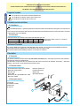
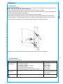
CAME F1024 is a powerful 24V swing gate motor engineered for intensive use in residential and condominium settings. With a maximum torque of 470 Nm and adjustable opening time, it can handle gates up to 4 meters long and weighing up to 800 kg. Its IP54 protection rating ensures resistance to harsh weather conditions. The CAME F1024 comes with a built-in electro-blocking system for added security and features easy-to-use electronic adjustments for precise gate control.
CAME F1024 is a powerful 24V swing gate motor engineered for intensive use in residential and condominium settings. With a maximum torque of 470 Nm and adjustable opening time, it can handle gates up to 4 meters long and weighing up to 800 kg. Its IP54 protection rating ensures resistance to harsh weather conditions. The CAME F1024 comes with a built-in electro-blocking system for added security and features easy-to-use electronic adjustments for precise gate control.


-
 1
1
-
 2
2
-
 3
3
-
 4
4
-
 5
5
-
 6
6
-
 7
7
-
 8
8
-
 9
9
-
 10
10
-
 11
11
-
 12
12


CAME F1024 is a powerful 24V swing gate motor engineered for intensive use in residential and condominium settings. With a maximum torque of 470 Nm and adjustable opening time, it can handle gates up to 4 meters long and weighing up to 800 kg. Its IP54 protection rating ensures resistance to harsh weather conditions. The CAME F1024 comes with a built-in electro-blocking system for added security and features easy-to-use electronic adjustments for precise gate control.
Ask a question and I''ll find the answer in the document
Finding information in a document is now easier with AI
Related papers
-
CAME DC02EARY User manual
-
-
-
-
-
-
-
-
-
Other documents
-
BFT JOINT Owner's manual
-
 NiceHome Maestro 200 Owner's manual
-
LiftMaster LA250EVK Installation guide
-
 Motostar ESC500 Usage And Maintenance Manual
-
Centurion BENINCA IT24N Installation Instructions Manual
-
-
Erreka Mole Swing Gate Opener Owner's manual
-
 Motorline SP WING 400 Operating instructions
-
 Mhouse WS2 Owner's manual
-
 Allmatic MOVEO 600KG 230V User manual


