Page is loading ...

I
I
N
N
S
S
T
T
A
A
L
L
L
L
A
A
T
T
I
I
O
O
N
N
I
I
N
N
S
S
T
T
R
R
U
U
C
C
T
T
I
I
O
O
N
N
S
S
Model: Industrial
QUESTIONS OR CONCERNS CONTACT CANARM AT:
1-800-265-1833 (English)
1-800-567-2513 (French)
Monday through Friday 8:00 a.m. to 5:00 p.m. E.S.T.
CP56
11/12
L
I
G
H
T
I
N
G
&
F
A
N
S
E
C
L
A
I
R
A
G
E
S
&
V
E
N
T
I
L
A
T
E
U
R
S
NOTE: FOR OPTIMUM QUIETNESS, FULLY ASSEMBLE FAN AND RUN 24 HOURS
CANARM LTD.
2157 Parkedale Ave.,
Brockville, Ontario
K6V 5V6
PH: (613) 342-5424
FX: (613) 342-8437
CANARM L
TEE.
8500 Rue Grenache,
Anjou, Quebec
H1J 2B1
PH: (514) 353-2255
FX: (514) 353-2522
CANARM 5 YEAR LIMITED WARRANTY
“THANK YOU” for purchasing a Canarm product. It is our policy to furnish you with
high quality products at a fair price. With proper installation your fan should provide you with
years of money saving comfort.
This fan is guaranteed to be free from defects in workmanship and material for a
period of five (5) years from date of purchase. Within the first (1) year from date of
purchase any defective product should be returned to your RETAIL OUTLET along with proof
of purchase. For the balance of the warranty, four (4) years, the MOTOR WINDINGS ONLY
,
shall be free of defects. We will correct such defects or replace the motor assembly at our
option if the product is returned, FREIGHT PREPAID, to Canarm. The returned fan must be
accompanied by your proof of purchase and a cheque for $20.00 for handling and
labour charges.
All costs of removing and re-installing the product are YOUR RESPONSIBILITY
.
Damage to any part as such by accident, misuse, improper installation or by affixing any
accessories IS NOT covered by this
warranty. As a result of varying climatic conditions in our
area this warranty does not cover any changes in finishes, including rusting, pitting, corroding,
tarnishing or peeling.
WARRANTY VOID: In cases of alteration, abuse, installation not in accordance with
instructions or REMOV
AL of the C.S.A. Sticker
.
!
“INSTRUCTIONS PERTAINING TO RISK OF FIRE OR INJURY TO PERSONS”
INSTALLATION AND WIRING TO BE IN ACCORDANCE WITH CEC,
NEC, LOCAL ELECTRICAL CODES and ANSI/NFPA 70.
Consult a qualified electrician if you are not familiar with wiring.
“READ ALL INSTRUCTIONS”
“IMPORTANT SAFETY
INSTRUCTIONS”
“SAVE THESE INSTRUCTIONS”
TOOLS AND MATERIALS REQUIRED
- Philips Screw Driver
- Blade Screw Driver
- Step Ladder
- Wire Cutters
- Wiring supplies as required by electrical code.
Note to Installer: You are obligated to pass these instructions on to
building maintenance or location Supervisor.

Pg. #2
Pg. #11
WARNING
1.
To
reduce
the
risk
of
personal
injury DO
NOT bend
the
blade
brackets
when
installing
the
brackets,
balancing
the
blades
or
cleaning
the
fan. Also,
DO
NOT insert
foreign
objects
in
between
rotating
fan
blades.
Mount
with
the
lowest
moving
parts
at
least
above
floor
or
grade
level.
SAFETY PRECAUTIONS
1. Turn off power at main electrical service box before starting installation.
2. Electrical connections must comply with local code ordinances, national
electrical codes, CEC, NEC and ANSI/NFPA 70.
3. Make sure the installation site you choose allows the fan blades to rotate
freely without any obstructions.
4. When mounting the fan on a ceiling outlet box, Use an approved (CSA for
Canada and UL for U.S.) ceiling fan box marked "FOR FAN SUPPORT".
5. WARNING: To reduce the risk of fire, electric shock, or personal injury,
6. Total Fan Weight: approximate 5.5 kgs (12.13 lbs).
mount fan only to an outlet box marked acceptable for fan support and use
mounting screws provided with the outlet box. Most outlet boxes commonly
used for the support of lighting fixtures are not acceptable for fan support
and may need to be replaced. Consult a qualified electrician if in doubt.
Remove fan from the carton carefully and check for shipping damage.
Check blades for bends and dents. In case assistance is required please
contact our service centre.
All set screws must be checked and re-tightened where necessary after
installation. No lubricants should be used on screws
or hooks.
To
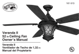
reduce the risk of personal injury install the safety cable (per Fig. 1).
DO NOT attach blades before hanging the fan.
2.
3.
To reduce the risk of fire or electrical shock, ONLY use WAROF-02 wall
control for speed control.
7.
4.
5.
6.
3.05 Meters
(10 Feet)
Ensure the outlet box is securely installed in place such that it is able to
support at least the fan weight.

Pg. #10
Pg. #3
1. Wooden Joist
2. Approved (CSA for Canada
and UL for U.S.) ceiling fan box
(not provided)
3. Ceiling
4. J-Hook
5. Rubber Gasket
6.
7.
Mounting Plate
8.
Outlet Box Screws (not provided)
10.
11.
Jam Screw
12.
13.
1.
2.
3.
4.
5.
6.
7.
11.
ASSEMBLY DRAWING
Fig.
1
Blade
Downrod c/w Ground Wire
Ceiling Canopy
Wall Control
Motor Assembly
9.
10.
8.
13.
9.
12.

1
1
.
.
Pg. #4
Pg. #9
INSTALL MOUNTING BRACKET
- Install J-Hook through centre of outlet box and into the wooden joist.
- Secure mounting plate and rubber gaskets to outlet box by outlet box screws.
- Hang the safety cable onto the J-hook.
- Hang fan on mounting plate
J-Hook
Ceiling
Wood Joist
Outlet Box
Rubber Gasket
Mounting Plate
Fig. 2a
Outlet box
Screws
WARNING: To Reduce The Risk Of Fire, Electric Shock, Or Personal
Injury, Mount To UL/CSA Listed Outlet Box Marked Acceptable for
Fan Support And Use Mounting Screws Provided With The Outlet Box.
Fig. 2b
Safety Cable
Fig. 2c
(not provided)

Pg. #8
Pg. #5
2
2
.
.
NOTE: Once ground wires are connected, carefully tuck all wires and marrettes
into the metal outlet box making sure that the wires are clear of the
hemisphere and downrod when positioned in mounting bracket.
ELECTRICAL HOOK-UP
Make the following wire connections to the receiver unit (see fig. 3) using the
wire nuts supplied.
-
-
-
-
-
In Quebec, the installation of this product must
be carried out by a qualified electrician.
Fig.3
Connect GREEN fan wire to BARE Copper wire or GREEN housheld
Connect BLACK fan wire to BLACK household supply wire.
Connect WHITE fan wire to WHITE household supply wire.
After making the wire connections, ensure the wires should be spread
apart with the grounded conductor and the equipment-grounding
conductor on one side of the outlet box and the ungrounded conductor
on the other side of the outlet box.
Ensure the splices after being made should be turned upward and
pushed carefully up into the outlet box.
supply wire.
120V AC
SUPPLY
BLACK
WHITE
OUTLET BOX
GROUND
GREEN
TO MOTOR L
AC IN L
BLACK wire
BLACKBLACK
WHITE
BLACK
(from main power)
BLACK wire
(from ceiling outlet box)
TROUBLESHOOTING
TROUBLE
SUGGESTIONS
- Check fuses and circuit breakers.
1. Fan will not start - Check wiring connections to fan.
- Check wiring connections in switch housing.
CAUTION: Turn power off for last two items.
2. Fan sounds noisy - Check to make sure that all screws in motor housing are snug.
- Check to make sure that blade bracket screws are tight.
- Allow a 24 hour break in period to eliminate most noises.
3. Fan wobbles - Check that all blades are screwed firmly into blade brackets.
or shakes
excessively.
- Check that blade brackets are secured firmly to motor.
- Check distance from tip of blades to ceiling.
- Check distance between blade tip to blade tip. All
measurements should be equal. Loosen blade
screws and position blade until even then re-tighten.
- Check to make sure that jam screws in downrod are tightened.
- Make sure canopy and mounting bracket are
tightened securely to wooden joist.

Tighten the canopy of jam screw.
Mount the blade on motor assembly.
LORTNOC LLA W FO NOITALLATSNI
Pg. #6
Pg. #7
3
3
.
.
4
4
.
.
INSTALLATION
FINAL
Blade
Bracket Screw
Blade
Motor
Lock Washer
Fibre
Bracket
Gasket
Fig. 5a
Fig. 5b
Jam Screw
Jam Screw
Ceiling
Canopy
A
B
Fig. 4
Connect BLACK wall control wire (marked with “AC in L”) to the
BLACK wire form main power on the wall outlet box.
Connect BLACK wall control wire (marked with “TO Motor L”) to the
BLAKC wire that connected to the BLACK wire of the fan from ceiling.
1.Connect the wires as shown.
3.Install the mounting plate to the outlet box by 2 outlet box
2.Carefully push wire nuts into the outlet box after connections.
screws (not supplied).
4.Push firmly the front cover into the wall unit.
FAN SPEED CONTROL
LOW
HIGH
4
3
2
1
0
Fig. 6
Wire Nut
BLACK wire
KNOB
FRONT COVER
SCREW
BLACK
AC IN L
TO MOTOR L
BLACK
OUTLET BOX
(from main power)
(from ceiling outlet box)
BLACK wire
WHITE
(when
applicable)
/