Page is loading ...

Solar Drainback or
Pressurized Water
Heating System Kit
Installation
Start-Up
Maintenance
Parts
Warranty
For Residential and
Commercial Use
**-32-KIT, -40-KIT, -64-KIT, -80-KIT, -96-KIT Models
** “DB” Denotes Drainback Kits
**“PR” Denotes Pressurized Kits
This manual must only be used by a qualied installer / service technician. Read all instructions in this manual before
installing. Perform steps in the given order. Failure to do so could result in substantial property damage, severe
personal injury, or death.
HTP reserves the right to make product changes or updates without notice and will not be held liable for
typographical errors in literature.
NOTE TO CONSUMER: PLEASE KEEP ALL INSTRUCTIONS FOR FUTURE REFERENCE.
272 Duchaine Blvd. New Bedford, MA 02745 www.htproducts.com
lp-626 Rev. 2.15.17

lp-626 Rev. 2.15.17
2
The following dened terms are used throughout this manual
to bring attention to the presence of hazards of various risk
levels or to important product information.
DANGER indicates an imminently hazardous situation which,
if not avoided, will result in serious personal injury or death.
WARNING indicates a potentially hazardous situation which, if
not avoided, could result in personal injury or death.
CAUTION indicates a potentially hazardous situation which, if
not avoided, may result in moderate or minor personal injury.
CAUTION used without the safety alert symbol indicates
a potentially hazardous situation which, if not avoided, may
result in property damage.
NOTICE is used to address practices not related to personal
injury.
Table of Contents
Part 1 - General Safety Information 3
A. When Servicing the Solar Water Heating System 3
B. Local Installation Regulations 3
C. Chemical Vapor Corrosion 3
D. Water Temperature Adjustment 3
E. Freeze Protection 4
Part 2 - Prepare the Solar Water Heating System Kit 4
A. What’s Included in the Kit 4
B. Locating the Solar Water Heating System 4
Part 3 - Installing the Drainback System Kit 5
A. Installing Solar Collector Components 5
B. Connecting the Return Solar Flex Lines 5
C. Completing Solar Water Heating System Piping 6
D. Applications 7
Part 4 - Installing the Pressurized System Kit 8
A. Installing Solar Collector Components 8
B. Connecting the Supply and Return Solar Flex Lines 8
C. Pump Control Station 9
D. Completing Solar Water Heating System Piping 9
E. Applications 10
Part 5 - Wiring 11
A. Installation Must Comply With 11
B. Wiring the Solar Water Heating System Components 11
Part 6 - Start-Up and Operation 11
Part 7 - Maintenance and Troubleshooting 11
Parts Included in Kit 12
Foreword
This manual is intended to be used in conjunction with other
literature provided with the Solar Water Heater and Solar
Collector. This includes all related control information. It is
important that this manual, all other documents included with
the solar system, and additional publications, such as Solar Water
Heating System Design and Installation Guidelines, SRCC OG-300,
be reviewed in their entirety before beginning any work.
Installation should be made in accordance with the regulations
of the Authority Having Jurisdiction, local code authorities, and
utility companies which pertain to this type of water heating
equipment.
Authority Having Jurisdiction (AHJ) – The Authority Having
Jurisdiction may be a federal, state, local government, or
individual such as a re chief, re marshal, chief of a re
prevention bureau, labor department or health department,
building ocial or electrical inspector, or others having statutory
authority. In some circumstances, the property owner of his/her
agent assumes the role, and at government installations, the
commanding ocer or departmental ocial may be the AHJ.
NOTE: HTP, Inc. reserves the right to modify product technical
specications and components without prior notice.
For the Installer
For your safety, please read through this manual carefully
before installation to minimize the risk of re, property damage,
personal injury, or death. Ensure the solar hot water system is
properly installed before use.
INSTALLATION OR SERVICE OF THIS SOLAR SYSTEM IS
REQUIRED TO BE PERFORMED BY LICENSED PROFESSIONALS
WHERE SOLAR, PLUMBING, AND ELECTRICAL WORK IS
REQUIRED.
The installer should be guided by the instructions furnished
with the tank, as well as local codes and utility company
requirements. Preference should be given to codes
and requirements where they dier from the furnished
instructions. Always use the latest edition of codes.
Additional publications which should guide the installer
include:
Local, state, provincial, and national codes, laws, regulations,
and ordinances.
Solar Water Heating System Design and Installation Guidelines,
SRCC OG-300, available from Solar Rating & Certication
Corporation, 400 High Point Drive, Suite 400, Cocoa, FL
32926-6630, www.solar-rating.org.
Code for the Installation of Heat Producing Appliances (latest
version), available from the American Insurance Association,
85 John Street, New York, NY 11038.
The latest version of the National Electrical Code, NFPA No. 70.
In Canada refer to Canadian Electrical Code C 22.1, from
Canadian Standards Association, 5060 Spectrum Way, Suite
100, Mississauga, Ontario, Canada L4W 5N6.

lp-626 Rev. 2.15.17
3
Part 1 - General Safety Information
Installer - Read all instructions in this manual before installing.
Perform steps in the given order.
User - This manual is for use only by a qualied heating
installer / service technician. Have the solar water heating
system serviced / inspected annually by a qualied service
technician.
Failure to adhere to these guidelines can result in substantial
property damage, severe personal injury, or death.
NOTE: Obey all local codes. Obtain all applicable permits
before installing the solar system.
NOTE: Install all solar system components and piping in such
a manner that does not reduce the performance of any re
rated assembly.
A. When Servicing the Solar Water Heating System
To avoid electric shock, disconnect electrical supply before
performing maintenance.
To avoid severe burns, allow solar collector and associated
equipment to cool before servicing.
Pipe runs must be solidly attached with proper clamping
methods. Soldered connections should be secured with 95/5
lead-free solder. Use only pipe rated for 250
o
F minimum on
both the collector return and supply piping.
B. Local Installation Regulations
Installation of this solar water heating system may be
governed by individual local rules and regulations for this
type of system, which must be observed. Always use the
latest edition of codes. The installation, adjustment, service,
and maintenance of the solar water heater must be done by
a licensed professional who is qualied and experienced in
NOTE: If the solar water heating system is exposed to the
following, do not operate. Immediately call a qualied service
technician.
1. Fire
2. Damage
3. Submersion in Water
Failure to adhere to these guidelines can result in substantial
property damage, severe personal injury, or death.
Only use this solar hot water system as intended and
described in this installation manual. Any use other than
described will void warranty and may lead to re, property
damage, personal injury, or death.
High heat sources (sources generating heat 100
o
F / 37
o
C or
greater, such as stove pipes, space heaters, etc.) may damage
plastic components of the water heater as well as plastic
vent pipe materials. Such damages ARE NOT covered by
warranty. It is recommended to keep a minimum clearance of
8” from high heat sources. Observe heat source manufacturer
instructions, as well as local, state, provincial, and national
codes, laws, regulations and ordinances when installing this
water heater and related components near high heat sources.
Improper installation or use may result in property damage.
Such damages ARE NOT covered by warranty.
the installation, service, and maintenance of solar hot water
systems.
C. Chemical Vapor Corrosion
Products to Avoid
Areas Likely to Have
Contaminants
Spray cans containing
uorocarbons
Dry cleaning / laundry areas
and establishments
Permanent wave solutions Swimming pools
Chlorinated waxes / cleaners Metal fabrication plants
Chlorine-based swimming pool
chemicals
Beauty shops
Calcium chloride used for thawing Refrigeration repair shops
Sodium chloride used for water
softening
Photo processing plants
Refrigerant leaks Auto body shops
Paint or varnish removers Plastic manufacturing plants
Hydrochloric or Muriatic acid
Furniture renishing areas and
establishments
Cements and glues New building construction
Antistatic fabric softeners used in
clothes dryers
Remodeling areas
Chlorine-type bleaches, laundry
detergents, and cleaning solvents
Garages and workshops
Adhesives used to fasten building
products
Table 1 - Products and Areas Likely to Have Contaminants
NOTE: DAMAGE TO THE WATER HEATER, COLLECTOR,
OR RELATED COMPONENTS CAUSED BY EXPOSURE TO
CORROSIVE VAPORS IS NOT COVERED BY WARRANTY.
(Refer to the limited warranty for complete terms and
conditions.)
D. Water Temperature Adjustment
An ASSE 1017 rated mixing valve to avoid severe burns or death
from scalding temperatures IS REQUIRED PER SRCC OG-300.
An ASSE 1017 rated mixing valve is included in this kit. Install the
mixing valve on the domestic water heating side of the system
following the instructions included with the mixing valve and
the solar water heater.
Approximate Time / Temperature Relationships in Scalds
120
o
F More than 5 minutes
125
o
F 1 1/2 to 2 minutes
130
o
F About 30 seconds
135
o
F About 10 seconds
140
o
F Less than 5 seconds
145
o
F Less than 3 seconds
150
o
F About 1 1/2 seconds
155
o
F About 1 second
Table 2 - Approximate Time / Temperature Relationships in Scalds
Households with small children, disabled, or elderly persons
may require a 120
o
F or lower temperature setting to prevent
severe personal injury or death due to scalding.

lp-626 Rev. 2.15.17
4
B. Locating the Solar Water Heating System
Part 2 - Prepare the Solar Water Heating System Kit
Carefully consider installation when determining solar water
heating system location. Please read the entire manual before
attempting installation. Failure to properly take factors such as
piping and wiring into account before installation could result
in wasted time, money, and possible property damage and
personal injury.
In addition, to prevent scalding, the high temperature of the
potable water must be limited using an ASSE 1016 tempering
valve. This valve is usually located between the hot water storage
tank and faucets in bathrooms, kitchens, etc. Tempering valves
are mandatory under most codes and usually set to a maximum
of 120
o
F. Tempering valves must be rated for high-temperature
solar use.
E. Freeze Protection
NOTE: Consider piping and installation when determining
water heater location. Place the water heater in a location not
prone to freezing.
Failure of the water heater, solar system, or components due
to freeze related damage IS NOT covered by product warranty.
In order to meet health and safety regulations, solar system
antifreeze uid should be food grade polypropylene glycol,
FDA rated as “generally recognized as safe” (GRAS). The
recommended glycol is DOWFROST or equivalent. Using
proper concentrations of glycol, solar systems can be operated
at ambient temperatures as low as -60
o
F. Freeze tolerance limits
are based upon an assumed set of environmental conditions.
Refer to the specication sheet included with the glycol for
recommended concentrations. A glycol/water mix must not
exceed 50%, unless the manufacture species that a dierent
ratio is recommended for use with solar water heaters. Glycol
may need to be changed periodically (every 3-5 years) to prevent
it from becoming acidic; please refer to the guidelines provided
by the glycol manufacturer regarding replacement.
NOTE: The use of glycol not recognized as GRAS is allowed in
double wall heat exchanger models ONLY.
Remove all sides of the shipping crate to inspect the Solar Water
Heating System Kit and move components to the installation
location.
UNCRATING THE SOLAR WATER HEATING SYSTEM KIT
- Any claims for damage or shortage in shipment must be
led immediately against the transportation company by the
consignee.
See the Replacement Parts tables at the end of this manual
for lists of the components included in the solar water heating
system kit.
A. What’s Included in the Kit
COLD WEATHER HANDLING - If the Solar Water Heating
System Kit or associated components have been stored in a
very cold location (BELOW 0
o
F) before installation, handle with
care until the components come to room temperature. Failure
to do so could result in damage to the components.
To avoid long pipe runs, the collector(s) should be positioned
as close as possible to the storage tank. Storage tank location
should therefore be considered part of the location requirements
of the solar collector(s). The storage tank should be located as
close as possible to the most frequent draw o points in the
building.
Solar water heaters are certied for indoor use only. DO NOT
INSTALL OUTDOORS. Outdoor installations ARE NOT covered
by warranty.
Choose a location for the solar water heating system as
centralized to the domestic piping system as possible. Also,
locate the solar water heating system and piping where it will
not be exposed to freezing temperatures. All piping should be
insulated. Additionally, place the solar water heating system
Zone Manifold so that the components and connections are
easily accessible.
Follow all the instructions included with the solar water heater
and components when locating and installing this solar water
heating system.

lp-626 Rev. 2.15.17
5
Part 3 - Installing the Drainback System Kit
A. Installing Solar Collector Components
Ensure the solar collectors are moved to the installation
location BEFORE installing the solar collector components.
Solar collectors are very heavy. Installing the solar collector
components BEFORE moving the collectors to the installation
location will increase the risk of damage to the collectors,
substantial property damage, severe personal injury, or
death.
Solar collectors are very heavy. Use caution as to not drop the
collectors when moving to the installation location. Dropping
the collectors could result in damage to the collectors,
substantial property damage, severe personal injury, or
death.
Figure 1 - Collector Unions
1. a. SINGLE COLLECTOR INSTALLATIONS - Continue to Step
2.
b. MULTIPLE COLLECTOR INSTALLATIONS - Use two pipe
wrenches to install the collector unions and manifold the
collectors. See Figure 1. Ensure O-Rings are installed on the
collector adapters before installing the unions.
2. Install caps on the unused collector adapters. Ensure O-Rings
are installed on the collector adapters before installing the caps.
See Figure 2.
Figure 2 - Installed Cap
3. Install the 90
o
elbow into the collector supply adapter. Ensure
O-Rings are installed on the collector supply adapter before
installing the 90
o
elbow.
4. Install the 90
o
elbow into the collector return adapter. Ensure
O-Rings are installed on the collector return adapter before
installing the 90
o
elbow. See Figures 3 and 13.
Figure 3 - Installed 90
o
Elbow
1. Install the male to male solar ex line adapter into the elbow
installed on the solar collector return adapter. See Figure 3.
2. Install the solar ex line with sensor into the solar collector
return adapter. Ensure the adapter and reinforcing ring are
positioned as described in Figure 4. See Figure 5 for installed
solar ex line.
Figure 4 - Adapter and Reinforcing Ring on Solar Flex Line
B. Connecting the Return Solar Flex Lines
Figure 5 - Installed Solar Flex Line
3. Run the solar collector return ex line to the inlet on the top
of the drainback tank. Use thread tape to connect the male to
female adapter to the drainback tank inlet.
Use two pipe wrenches to install the solar ex line to the
drainback tank inlet adapter. Ensure the adapter and reinforcing
The design and installation of the solar water heating system
should be done by qualied individuals. It is important that
good design and installation practices be followed to ensure
the system will operate properly. Failure to follow installation
guidelines for your solar water heating system could cause
component failure and possible safety issues.
It is mandatory that all plumbing be done in accordance
with local and state codes or warranty will be void. It is also
necessary to use both thread tape and pipe dope on all
mechanical connections.
Provide clear access to the water heater, pump, drainback
tank, mixing valve, and other key components.
NOTE: These instructions do not detail how to install the solar
collectors. Refer to the solar collector instructions for detailed
installation information.
Never use dielectric unions or galvanized steel ttings in
the collector loop. Doing so will lead to corrosion, property
damage, and possible early water heater failure. Such
damage IS NOT covered by warranty. Use only copper and
brass ttings.
Use two wrenches when tightening connections. Use one
wrench to prevent the return or supply line adapters from
turning. DO NOT OVERTIGHTEN. Failure to prevent piping
adapters from turning could cause damage to heater
components.
Do not install check valves or vacuum breaks in a drainback
system. Doing so will result in premature component or
system failure.

lp-626 Rev. 2.15.17
6
Figure 6 - Installing the Solar Flex
Line on the Drainback Tank Inlet
Figure 7 - Installed Tee, Temp.
Gauge, and Relief Valve
Figure 8 - Installing the Solar Flex Line on the Drainback Tank Outlet
6. Run the return solar ex line to the inlet on the solar water
heater heat exchanger. See Figure 9. Install the solar ex line to
the inlet on the solar heat exchanger on the water heater. See
Figure 10. Ensure the adapter and reinforcing ring are positioned
as described in Figure 4.
5. Connect the male to female adapter to the drainback tank
outlet. Then use two pipe wrenches to install the solar ex line
to the adapter. Ensure the adapter and reinforcing ring are
positioned as described in Figure 4. See Figure 8 for installed
solar ex line.
ring are positioned as described in Figure 4. See Figure 6 for
installed solar ex line.
4. Install the tee onto the adapter provided on the solar drainback
tank.
Install the male to male threaded adapter into the tee.
Install the pressure relief valve provided with the drainback tank
onto the threaded adapter.
Install the pressure gauge into the tee. See Figure 7.
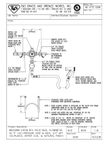
C. Completing Solar Water Heating System Piping
Figure 9 - Installing the Return
Solar Flex Line to the Heat
Exchanger Inlet
Figure 10 - Installed Return Solar
Flex Line on the Heat Exchanger
Inlet
1. Install the tee onto the outlet of the solar water heater heat
exchanger.
Install the male to male threaded adapter into the top of tee.
Install the drain valve into the bottom of the tee.
Install the pump into the tee.
Install the female to male adapter on the pump.
Install the solar ex line to the pump adapter. Ensure the
adapter and reinforcing ring are positioned as described in
Figure 4. See Figures 11 and 12.
Figure 11 - Installing the Tee,
Pump, and Drain Valve
Figure 12 - Installed Tee, Pump,
Drain Valve, and Solar Flex Line
2. Run the solar ex line to the collector supply connection.
Connect the male to female adapter into the elbow installed
on the collector supply connection.
Install the solar ex line to the adapter. Ensure the adapter and
reinforcing ring are positioned as described in Figure 4.

lp-626 Rev. 2.15.17
7
Part Description Part Description
A Elbow K Collector Sensor Wire (Included with Solar Control)
B Coupling L Three Speed Solar Pump
C Cap M 1” X 2” Brass Nipple
D 3/4” X 1” Male Reducer N 3/4” X 3/4” X 1” Brass Tee
E 3/4” Mixing Valve O 3/4” Drain Valve
F Solar Control P 60 PSI Pressure Gauge
G Solar Flex Line with Sensor Q 3/4” X 3/4” X 1/4” Brass Tee
H 3/4” SST Adapter Straight Female R 3/4” Nipple
I 3/4” NPT Union Set S Temperature and Pressure Relief Valve (Comes with Drainback Tank)
J Solar Flex Line without Sensor
D. Applications
Figure 13 - Drainback Kit Installation
Table 3 - Drainback Kit Parts

lp-626 Rev. 2.15.17
8
Part 4 - Installing the Pressurized System Kit
A. Installing Solar Collector Components
Ensure the solar collectors are moved to the installation
location BEFORE installing the solar collector components.
Solar collectors are very heavy. Installing the solar collector
components BEFORE moving the collectors to the installation
location will increase the risk of damage to the collectors,
substantial property damage, severe personal injury, or death.
Solar collectors are very heavy. Use caution as to not drop the
collectors when moving to the installation location. Dropping
the collectors could result in damage to the collectors,
substantial property damage, severe personal injury, or death.
Figure 14 - Collector Unions
1. a. SINGLE COLLECTOR INSTALLATIONS - Continue to Step
2.
b. MULTIPLE COLLECTOR INSTALLATIONS - Use pipe wrenches
to install the collector unions and manifold the collectors. See
Figure 14. Ensure O-Rings are installed on the collector adapters
before installing the unions.
2. Install caps on the unused collector adapters. Ensure O-Rings
are installed on the collector adapters before installing the caps.
See Figure 15.
Figure 15 - Installed Cap
3. Install the 90
o
elbow into the collector supply adapter.
Ensure O-Rings are installed on the collector supply adapter
before installing the 90
o
elbow. See Figures 16 and 24.
Figure 16 - Installed 90
o
Elbow
1. Install the male to male solar ex line adapters into the
open end of the tees on the solar collector return and supply
adapters.
2. Install the solar ex line with sensor into the solar collector
return adapter, and the solar ex line without sensor into
the solar collector supply adapter. Ensure the adapters and
reinforcing rings are positioned as described in Figure 17. See
Figure 18 for installed solar ex line.
Figure 17 - Adapter and Reinforcing Ring on Solar Flex Line
B. Connecting the Supply and Return Solar Flex Lines
Figure 18 - Installed Solar Flex Line
3. Run the solar collector return and supply ex lines to the
pump control station.
The design and installation of the solar water heating system
should be done by qualied individuals. It is important that
good design and installation practices be followed to ensure
the system will operate properly. Failure to follow installation
guidelines for your solar water heating system could cause
component failure and possible safety issues.
It is mandatory that all plumbing be done in accordance with
local and state codes or warranty will be void. It is also necessary
to use both thread tape and pipe dope on all mechanical
connections.
Provide clear access to the water heater, pump, expansion tank,
mixing valve, and other key components.
NOTE: These instructions do not detail how to install the solar
collectors. Refer to the solar collector instructions for detailed
installation information.
Never use dielectric unions or galvanized steel ttings in the
collector loop. Doing so will lead to corrosion, property damage,
and possible early water heater failure. Such damage IS NOT
covered by warranty. Use only copper and brass ttings.
Use two wrenches when tightening connections. Use one wrench
to prevent the return or supply line adapters from turning. DO
NOT OVERTIGHTEN. Failure to prevent piping adapters from
turning could cause damage to heater components.
4. Install the 1” x 1” x 1/2” tee onto the collector supply adapter.
Ensure O-Rings are installed on the collector supply adapter
before installing the tee.
Use thread tape to install the shut-o air vent valve into the
1/2” adapter on the tee.
Use thread tape to install the automatic air vent into the shut
o valve.

lp-626 Rev. 2.15.17
9
Figure 19 - Installed Male to
3/4” Female Adapter
Figure 20 - Installed Male to
Male Adapter
Figure 21 - Remove the Black Pipe and Install the Pump
1. Use thread tape and pipe dope to install the four (4) male to
3/4” female adapters in the pump control inlets and outlets.
See Figure 19.
2. Use thread tape and pipe dope to install the four (4) male to
male adapters in the pump control inlets and outlets. Ensure
the O-Ring is installed on the adapter as described in Figure
20.
D. Completing Solar Water Heating System Piping
Figure 22 - Installed the Solar Flex Line on the Pump Control Outlet
1. Install the solar system supply and return ex lines to the
pump control station top inlet and outlet. Ensure the adapters
and reinforcing rings are positioned as described in Figure 17.
2. Install the solar system supply and return ex lines to the pump
control station bottom inlet and outlet. Ensure the adapters and
reinforcing rings are positioned as described in Figure 17.
3. Run the solar system return and supply ex lines from the
pump control station to the inlet and outlet on the solar water
heater heat exchanger.
4. Use thread tape and pipe dope to connect the female to male
adapters on water heater heat exchanger inlet and outlet.
5. Install the solar system supply and return ex lines to the water
heater heat exchanger inlet and outlet. Ensure the adapters and
reinforcing rings are positioned as described in Figure 17. See
Figure 23.
C. Pump Control Station
3. Use thread tape and pipe dope to install the four (4) female
to male adapters in the pump control inlets and outlets.
4. Use pipe wrenches to remove the black pipe from the pump
control station. See Figure 21. Then use the pipe wrenches
and thread tape and pipe dope to install the three speed solar
pump into the pump control station.
NOTE: To ease installation, it may be necessary to entirely
remove the pump control station solar supply pipe. If this is
necessary, take note of how best to reinstall the solar supply
pipe, and the components necessary.
Figure 23 - Installed Solar Flex Line on the Heat Exchanger Inlet
5. Mount the pump control station in an appropriate
mounting location. See the pump control station installation
instructions for mounting information. Paper instructions
may not be included with the pump control station, and it
may be necessary to search the web for a digital copy of these
instructions.
6. Install the solar ex lines to the solar collector return and
supply lines of the pump control station. Ensure the nut,
adapter, and reinforcing ring are positioned as described in
Figure 17. See Figure 22.
7. Use thread tape and pipe dope to install the solar expansion
tank and ex line to the pump control station. Ensure the
expansion tank is properly supported and mounted. See
Figure 24 for a typical installation.
6. See Figure 24 for a completed typical installation.

lp-626 Rev. 2.15.17
10
Figure 24 - Pressurized Kit Installation
Part Description Part Description
A Elbow K Collector Sensor Wire (Included with Solar Control)
B Coupling L 3/4” Solar Flex Fitting Kit
C Cap M Dual Line Solar Station
D 3/4” X 1” Male Reducer N Three Speed Solar Pump
E 3/4” Mixing Valve O Solar Expansion Tank
F Solar Control P Expansion Tank Flex Line Kit
G Solar Flex Line with Sensor Q 1” FPT X 1/2” Tee Fitting
H 3/4” SST Adapter Straight Female R Shut O Valve
I 3/4” NPT Union Set S Air Vent
J Solar Flex Line without Sensor
Table 4 - Pressurized Kit Parts
E. Applications

lp-626 Rev. 2.15.17
11
Part 5 - Wiring
Wiring errors can cause improper and dangerous operation,
and possibly result in electrical shock. To avoid electrical
shock, turn o all power to the heating appliance and
controls when wiring. Ensure the power remains o while any
wiring connections are being made. Failure to follow these
instructions could result in component or product failures,
serious injury, or death. Such product failures ARE NOT
covered by warranty.
Jumping out control circuits or components WILL VOID
product warranty and can result in property damage, personal
injury, or death.
Label all wires prior to disconnecting them when servicing
the solar system. Wiring errors can cause improper and
dangerous operation. Failure to follow these instructions may
result in property damage or personal injury.
It is of extreme importance that all system components be
properly grounded. It is very important that the building
system ground is inspected by a qualied electrician prior to
making this connection. Electrical power must only be turned
on when the system is completely lled with cold water.
Failure to follow these instructions could result in component
or product failure, serious injury, or death.
Electrical Shock Hazard - Turn o electrical power supply
at service entrance panel before making any electrical
connections. Failure to follow do do so could result in serious
injury, or death.
Wiring must be NEC Class 1. If original wiring supplied with
the manifold must be replaced, use only TEW 105
o
C wire or
equivalent. The solar system must be electrically grounded
as required by the National Electrical Code, ANSI/NFPA 70 -
Latest Edition.
A. Installation Must Comply With
1. National Electrical Code and any other national, state,
provincial, or local codes or regulations.
2. In Canada, CSA C22.1, Canadian Electrical Code Part 1, and
any local codes.
B. Wiring the Solar Water Heating System Components
Part 6 - Start-Up and Operation
Each solar water heater ships with operating instructions.
Please refer to the instructions included with the water heater
and any other components that may be used in the solar water
heating system (drain back tank, solar control, pump station,
etc.) when starting up, programming, and operating the solar
water heating system.
Part 7 - Maintenance and Troubleshooting
DO NOT carry out any maintenance or cleaning of the solar
system before turning o the power supply. Failure to adhere
to these guidelines can result in substantial property damage,
electric shock, severe personal injury, or death.
1. To promote solar system reliability and safety it is
recommended to maintain and clean it a minimum of every
six months. Some installation conditions may require more
frequent cleaning.
2. Check the solar system for evidence of leakage. Repair any
leaks.
3. Ensure all wires are intact and properly connected.
4. In addition, please refer to the instructions included with the
water heater and any other components that may be used in the
solar water heating system (drain back tank, solar control, pump
station, etc.) when maintaining the solar water heating system.
1. Install the solar sensor wire gasket on the return side of the
solar collector. See Figure 25.
2. Locate the solar collector sensor bulb. See Figure 26.
Figure 25 - Installed Solar
Sensor Wire Gasket
Figure 26 - Solar Collector Sensor
Bulb
3. Run the solar collector sensor (the sensor with the black, UV
protected wire) through the solar sensor wire gasket. See Figure
27.
Figure 27 - Installing the Solar Sensor in the Solar Wire Gasket
NOTE: The sensor may run up or down through the solar wire
gasket, as required by installation conditions.
4. Install the solar sensor into the solar collector sensor bulb. See
Figure 28.
Figure 28 - Installing the Solar Sensor into the Sensor Bulb
5. To complete solar system wiring, please refer to the
instructions included with the components when wiring the
solar pump, water heater, and any controls that may be used in
the system.
NOTE: The included sensor with gray wire runs to the solar
water heater. See solar water heater manual for installation
instructions, and instructions included with the controls for
wiring instructions.

lp-626 Rev. 2.15.17
12
Set-Up Instructions for Drainback Systems
CAUTION
DO NOT wire the pump to the controller until the controller program pump function has been switched from
“Auto” to “OFF”. Only then should the pump be wired to the unpowered controller. After the pump is connected
control power can be restored.
Filling instructions:
Ensure pump is located 4‘ below DB tank.
Use 18/2 thermostat wire to connect sensors to the controller. The black sensor wire runs outside to the
collectors. Using shielded wire is advisable when the wire is located near other electrical sources.
Install and secure the collector sensor in the collector’s hot-out side sensor well to ensure an accurate
temperature reading.
Install the tank sensor into the provided control well or onto the sensor stud. If these are not available,
place the sensor on the cold DHW feed port against the tank, under the insulation and with direct contact
to the steel.
Locate the fill valve below the pump. Connect a filler hose to the valve.
Fill the system until fluid is 2" from the top of the DB tank sight glass.
Check pressure gauge. Ensure there is at least 10 to 20 psi in the cold system. (It is just water and easy to
drain and repair should a leak be detected. A high pressure air test is generally not needed.)
Ensure the system holds pressure over time. (If pressure does not hold, repair leaks and refill the system.)
Power the controller. Enter programming and set pump function to “OFF”.
Unplug controller and wire in the pump on R1.
Restore power the controller.
Locate the ¾” silver slotted air purge in the middle of the pump. Open to purge air from pump cavity.
On the solar controller, set the pump function to “ON”.
Determine that the water is returning to the DB tank and verify the pump can complete the circuit. The
water level on the sight glass will drop substantially.
Mark and document the water level’s lowest point on the sight glass with tape or a mark.
Use the solar controller to disengage the pump by setting pump function to “OFF”.
With the pump off, verify that the fluid level returns to the original high full mark. If it falls short, repair
plumbing for any leaks and ensure it pitches back to the DB tank for complete drainage. Restart filling test.
R
un the system and let it heat in the sun. Flush, drain, and refill if necessary.
When the system is ready to operate, set the pump function to “auto” in the solar controller.
Observe the system and verify heat transfer from solar collectors to the tank. Ensure sensor readings are
responding appropriately.
Observe and monitor solar performance over several days.
CAUTION: Included kit components are shown in this drawing. DO NOT add check valves, a vacuum break, expansion tanks, or air
eliminators. Check the pump and remove any internal check valve. This is a closed-loop sealed system.
2/14/17
2
4
5
3
1
2
3
askrod.com
Collector
sensor
askrod.com
Tank sensor
4
5
Set-up and filling instructions for
pressure closed-loop drainback systems
Install the drainback (DB) tank in a conditioned space or
add glycol to reduce freeze potential. Slope all plumbing
and collectors ¼” per foot to the DB tank. Adding glycol
does not supersede this slope for draining. Mount DB tank
as high as possible to reduce pump size and power
demands.
This drawing is meant for reference only. The installer is responsible for all equipment and detailing required by local codes. Installaon must comply
with state and local building codes. All
piping must be sized correctly to specific length and size, according to accepted engineering methods or codes.
HTP Inc. accepts no liability in the design, interpretaon, or installaon of this reference.
1
1
3
6
6
Figure 29 - Drainback System Set-Up

lp-626 Rev. 2.15.17
13
Programming Instructions for Drainback Systems
S1 S2
S3 S4
R1
Pressure closed-loop drainback
Programming collector to tank solar differential control
Simple description:
Most basic ∆T differential control. Solar transfer based on S1 and S2. Place tank
sensor in well or stud, or under insulation against steel of the cold inlet port. Programming below slows
pump down after collectors have been primed.
Sequence Description:
The controller monitors the collector temperature (S1) and tank temperature (S2). If the collector
temp is higher than 12° [programmable (DTO)] the pump (R1) will engage. Pump disengages if collector
temp comes within 8° [programmable (DTF)] of tank temp.
Required Sensors:
S1: Collector (black wire)
Sensor must sense inside collectors
S2: Bottom tank
Components:
C1: collectors, T1: primary tank or heat load, B1: wiring bus located under control cover
Outputs:
R1 = solar pump located 4' below DB tank with some horizontal piping if possible (bronze or stainless pump
sized for lift and collector[s] gpm)
C1 T1
Optional Sensors:
S3: For display purposes only
S4: Near solar pump, used to measure BTU's output.
B1
1 2 3 4 5 6 7 8
S1 S2 S3 S4
N R2 N R1 N L
Sensors Pumps relays
S1 S2
S3 S4
Optional
B1
Variable Default Range Description
ARR 1 NA Drainback Solar System in accord with this drawing
DT O 12° 8.5 – 40 ∆T required to start solar pump
DT F 8° 1 - 11.5 ∆T required to stop solar pump
DT S 40 3 – 60 ∆T where min pump speed (nMN) begins following startup at 100% for 10 seconds
RIS 4 2 – 40 ∆T rise required for pump to increase by 10%
nMN 40% 30 – 100 Lowest pump speed during modulation
S MX 170° 40 – 205 Tank temp set point, middle or bottom sensor (S2)
Glass lined tank maximum 140° Stainless steel 180°
EM 230 170-390 Maximum collector temperature before shut down
OCN off/on on \ off Minimum collector temperature mode
CMN 50/110° 50 – 195 Minimum collector temp to start solar pump (prevents pump cycling at night)
OCF off on/off Freeze protection. Engages pump in freezing conditions with no or low antifreeze
CFR n/a 15 – 50 Temp of collector when pump will run to prevent freezing if OCF is set to on
OHQM off/on on \ off Energy monitoring mode (
Set this to lend an approximation to the owner of BTU production)
FMAX __ 0 – 20 Maximum flow in liters per min (set to .75 gallon per number of collectors used)
MEDT __ 0 – 3 Type of anti-freeze (0=water, 1=prop glycol, 2=ethyl glycol, 3=Tyfocor)
MED% __ 20 – 70 Glycol percentage in system
ODB on on – off Drainback function
tDTO __ 1 – 100s Time to operate pump at 100% (DT O)
When commissioning, clock the time it takes for the pump to run and return into the DB tank. Put this time into tDTO
tFLL 1 min 1 – 30m Time to operate pump until ∆T reading can be achieved for accurate pump speed
tSTB 5 min 1 – 15m Time the pump must continue to postpone DT F
OBST off on/off Second booster pump
Man1 auto off\auto\on Relay #1 mode
Man2 n/a off\auto\on Relay #2 mode
LANG Eng
UNIT F° F° or C°
RESE Reset to default program
PROG Program number
VERS Version number
Suggested start-up settings for this drawing. Refer to the solar controller manual for more details.
1
3
askrod.com
Collector
sensor
askrod.com
Tank sensor
S1
C1
T1
S3
S2
S4
R1
R1
Figure 30 - Programming Instructions for Drainback Systems

lp-626 Rev. 2.15.17
14
Set-Up Instructions for Pressurized Closed-Loop with Glycol Systems
askrod.com
1
Collector
sensor
Tank sensor
Set-up and filling instructions for
pressurized closed-loop with glycol
Field Tools Needed:
Pressurized filling station or a high-head pressure pump that can generate at least 50 psi
Hoses for filling to connect to the field-supplied filling pump
Air compressor for pressure testing the system and setting the pressure on the expansion tank
Components and tools for roof flashing when a roof penetration is used
Standard spanner wrenches for tightening supplied fitting
This drawing is meant for reference only. The installer is responsible for all equipment and detailing required by local codes. Installaon must comply
with state and local building codes. All piping must be sized correctly to specific length and size, according to accepted engineering methods or codes.
HTP Inc. accepts no liability in the design, interpretaon, or installaon of this reference.
General Instruction:
Locate and mount collectors according to instructions
Use 18/2 thermostat wire to connect sensors to the controller. The black sensor wire
runs outside to the collectors. Using shielded wire is advisable when the wire is
located near other electrical sources.
Install and secure the collector sensor in the collector’s hot-out side sensor well to
ensure an accurate temperature reading.
Install the tank sensor into the provided control well or onto the sensor stud. If these are not available, place
the sensor on the cold DHW feed port against the tank, under the insulation and with direct contact to the
steel.
After system components are assembled and connected, dry pressure test the solar loop to 100 psi for an
extended period of time with the expansion tank and top collector air vent isolated from the system. This test
is important because the system will deal with stagnation, high temperatures with pressure spikes, and
extreme temperature variations.
If the lift distance from the tank to the collectors is >20' the approximate target pressure of the solar loop will
be 30 psi.
If the lift distance from the tank to the collectors is <20' the approximate target pressure of the solar loop will
be 40 psi.
Pre-charge the expansion tank to 2 to 3 psi above the target pressure (as determined by lift distance)
Consider the above only in a cold system with no exposure to sunlight.
Additional Notes:
The pump station is shipped in its own box with or without the pump inserted. All fittings in this pump station
must be checked for tightness and seal. Do not assume that shipping has not interfered with any of the fitting
seals.
Most of the solar loop fittings are sealed with O-rings and/or gaskets. Over-tightening is not necessary.
Page 1 of 2 – 2/14/17
Figure 31 - Pressurized Closed Loop Set-Up

lp-626 Rev. 2.15.17
15
Set-up and filling instructions for
pressurized closed-loop with glycol
This drawing is meant for reference only. The installer is responsible for all equipment and detailing required by local codes. Installaon must comply with
state and local building codes. All piping must be sized correctly to specific length and size, according to accepted engineering methods or codes. HTP Inc.
accepts no liability in the design, interpretaon, or installaon of this reference.
CAUTION
It is recommended to not begin this procedure with the collectors uncovered. Cover the collectors when you
work on the collectors even if it is overcast and there is little sun.
Filling the Solar System:
Locate the feed and return charging ports on the pump station and connect the field-supplied hose to the
filling pump. Close the isolation valve between the filling ports. Make sure that it is pumping in the same
direction as the solar pump is pumping to the inlet of the collectors.
Fill and charge the system. Circulate the fluid for 5 to 10 minutes to remove as much air as possible. While
the filler pump is still circulating, ensure all isolation valves are open and on the collector air vent and
expansion tank. Now open the valve between the filler ports. With the filler pump still operating, manually
turn on the solar pump (in the solar controller, change pump function from “ON”, “OFF”, and “Auto”). Allow
the system to purge as the fluid circulates through the system. If the sun is out, the fluid will begin to warm
even though the collectors are covered.
Start throttling down the return to the bucket valve and watch the pressure
start to build. It is OK if the filling pump begins to labor more. There are
two locations from which air bubbles will escape: 1) The automatic air vent
on the collector, and 2) the manual air trap on the left side of the pump
station. Try to maintain a higher circulation pressure for several minutes as
the micro bubbles are purged out of the system. Leave the system at
about 5 psi higher than the targeted pressure. The system needs to
operate and heat for a full day, under full sun, to purge the remainder of
the micro bubbles out of the system. Additional a
ir purging should be
considered again after several days of solar heating operation to eliminate
the final gathering of the micro bubbles in the air vents.
Ensure that the roof air vent isolation valve is not left open when you
leave. In the event of a power failure, a closed valve will allow the system
to stagnate normally as the collectors flash to steam; if the valve is open,
the automatic air vent will discharge and not be able to differentiate
between air and steam. If air is left in the system during stagnation,
flashing and air migration may create flow and pop-off the pressure relief
valve (PRV). Now steam expansion has extended outside of the collectors
into the plumbing and no PRV is able to contain it.
Leave the air vent open as long as you are there to naturally collect any micro bubbles while under hot
operating conditions. It is extremely important that all of the air is removed from the system. This is a task
that will require time and patience. You will have to return later to purge the air vent and pump station air
traps. Not completing the full air purge to initiate the system will lead to potential system failure.
After all air is purged, the system will operate under a full hot noon day environment at 10 to 15 psi above
target set cold pressure. Ensure the supplied PRV has a rating of 20 psi above cold setup pressure.
Ensure the controller is programmed correctly and that you can see appropriate readings from the sensors.
In the solar controller, change the pump function to Auto. Observe controller functions to ensure it is
operating automatically and initiating at appropriate times.
Page 2 of 2 – 2/14/17
Figure 32 - Pressurized Closed Loop Set-Up
Set-Up Instructions for Pressurized Closed-Loop with Glycol Systems

lp-626 Rev. 2.15.17
16
Programming Instructions for Pressurized Closed-Loop with Glycol Systems
S1 S2
S3
S4
Pressurized closed loop glycol
Simple description: Most basic ∆T differential control settings. Solar
transfer based on S1 and S2. Place tank sensor in sensor well or under
insulation against steel of the cold inlet port.
Sequence Description:
Controller looks at the collector temperature (S1) and tank temperature (S2). If the collector
temp is higher than 12° [programmable (DTO)] the pump (R1) will engage. Pump disengages if
collector temp comes within 8° [programmable (DTF)] of tank temp. Pump modulated to ∆T
Required Sensors:
S1: Collector (black wire)
S2: Bottom tank
Components:
C1: collectors
T1: primary tank or heat load (gas or electric back-up)
B1: wiring bus located under control cover
Outputs:
R1 = solar pump (can be modulated for variable speed or set to 100%)
T1
Optional Sensors:
S3, for display purposes only
S4, Before solar pump, used to aproximate BTU's output.
B1
Variable Default Range Description
ARR 1 NA Solar System Valve logic for pool heating or other storage vessel
DT O 12° 8.5 – 40 ∆T required to start solar pump
DT F 8° 1 - 11.5 ∆T required to stop solar pump
DT S 20° 3 – 60 ∆T where min pump speed (nMN) begins following startup at 100% for 10 seconds
RIS 4° 2 – 40 ∆T rise required for pump to increase by 10%
nMN 40% 30 – 100 Lowest pump speed during modulation
S MX 170° 40 – 205 Tank temp set point, middle or bottom sensor (S2) Stainless tanks can go to 180°, Glass only good to 140°
EM 270 170-390 Maximum collector temperature before shut down
OCC, CMX, OSYC, DTCO, DTCF, OSTC, OHOL,THOL,
OCN off/on on \ off Minimum collector temperature mode
CMN 50/110° 50 – 195 Minimum collector temp to start solar pump (Prevents from short pumping on hot nights)
OCF off on/off Freeze protection. Engages pump in freezing conditions with no or low antifreeze
CFR n/a 15 – 50 Temp of collector when pump will run to prevent freezing if OCF is set t
o on
OTC, TCST, TCEN, TCRU, TCIN
OHQM off/on on \ off Energy monitoring mode
FMAX 6.0 0 – 20 Maximum flow in liters per min (set to .75 gallon per number of collectors used)
MEDT 1 0 – 3 Type of anti-freeze (0=water, 1=prop glycol, 2=ethyl glycol, 3=Tyfocor)
MED% 45% 20 – 70 Glycol percentage in system
ODB off on – off Drainback function
Man1 auto off\auto\on Relay #1 mode
Man2 n/a off\auto\on Relay #2 mode
LANG Eng
UNIT F° F° or C°
RESE Reset to default program
PROG Program number
VERS Version number
Suggested start-up settings for this drawing. Refer to the solar controller manual for more details.
1 2 3 4 5 6 7 8
S1 S2 S3 S4
N R2 N R1 N L
Sensors Pumps relays
R1
B1
S1
S2 S3 S4
R1
C1
Optional
S1
S2
S3
S4
C1
T1
R1
Figure 33 - Pressurized Closed Loop with Glycol Programming

lp-626 Rev. 2.15.17
17
Part Number Description Quantity Part Number Description Quantity
SS-**-FP-UW Solar Collector Depends on Kit 8600-679 3/4” X 1” NIP Male Reducer 4
8600-625 Pre-Mixed Glycol 5 Gallons 8600-588 3/4” SST Adapter Straight 4
8600-586 3/4” Solar Flex Pipe w/ Sensor (50’ Coil) 1 8600-505 1” Cast 3 Speed Solar Pump 1
8600-587 3/4” Solar Flex Pipe w/o Sensor (50’ Coil) 1 S8600-092 Female 90
o
Flex Line Connector 1
8600-517 3/4” Sweat Mixing Valve 1 8600-030 Shut-O Valve for Air Vent 1
8600-632 Isolar Delta T Control 1 8600-029 Auto Air Vent 1
8600-525 3/4” NPT Union Set 2 8600-522 Mounting Kit 1
S8600-090 Male 90
o
Flexline Connector 1 8600-699 Dual Line Solar Station 1
8600-296 1” Cap with O-Ring 2 8600-532 Expansion Tank Flex Line Kit 1
8600-329 1” Female Brass Union with O-Rings Depends on Kit 8600-671 Solar Expansion Tank 1
8600-080 Solar Sensor Wire Gasket 1
Table 5 - Pressurized Kit Parts - Collectors are available in 32 and 40 Sq. Ft. Models
Part Number Description Quantity Part Number Description Quantity
SS-**-FP-UW Solar Collector Depends on Kit 8600-679 3/4” X 1” NIP Male Reducer 3
SSU-10DB 10 Gallon Solar Drainback Tank 1 8600-588 3/4” SST Adapter Straight 3
8600-586 3/4” Solar Flex Pipe w/ Sensor (50’ Coil) 1 8600-506 1” Cast 3 Speed Solar Pump 1
8600-587 3/4” Solar Flex Pipe w/o Sensor (50’ Coil) 1 8600-272 1/4” 60 PSI Pressure Gauge 1
8600-517 3/4” Sweat Mixing Valve 1 8600-273 3/4” X 3/4” X 1/4” Brass Tee 1
8600-632 Isolar Delta T Control 1 8600-276 1” X 2” Brass Nipple 1
8600-525 3/4” NPT Union Set 1 8600-275 3/4” X 3/4” X 1” FNPT Brass Tee 1
S8600-090 Male 90
o
Flexline Connector 2 8600-274 3/4” Drain Valve 1
8600-296 1” Cap with O-Ring 2 9500-0052 3/4” Brass Nipple 1
8600-329 1” Female Brass Union with O-Rings Depends on Kit
8600-080 Solar Sensor Wire Gasket 1
Table 6 - Drainback Kit Parts - Collectors are available in 32 and 40 Sq. Ft. Models
Parts Included in Kit
** - Denotes Total Surface Area of Collector(s) in Square Feet - Ex: SS-80-FP-UW will include two (2) SS-40-FP Collectors
/