SYMPTOM CAUSE(S) CORRECTIVE ACTION
1. Display will not come “ON” 1a. Jumper on back of clock is missing Set Jumper to proper location. See
when unit is powered up? or set incorrectly. Pg.7 of instruction manual.
1b. Fuse on back of clock blown open. Replace fuse with 1/8 amps fuse.
See Pg. 7 of instruction manual.
1c. Power to clock not present. Check connections to clock.
Check circuit breakers.
2. Freeze protection circuit not 2a. Freeze Probe (P/N 178PA28A) Install Intermatic freeze probe. See
working? not installed or bad. Pg. 7 of instruction manual.
2b. Clock programming not setup. Setup freeze programming. See
Pg. 7 of instruction manual.
3. Unit does not turn “ON” or 3a. Internal ON/OFF Times have Setup ON/OFF programming. See
“OFF” at desired times? not been defined. Pg.’s 24-27 of instruction manual.
3b. ON or OFF time is in override mode. Cycle through programming menu.
See Pg.’s 24-27 of instruction
manual.
3c.
Clock is in Freeze protection Review programming menu. See
Countdown Mode. Pg.’s 29 & 33 of instruction manual.
4.
Displa
y continues to blink ON 4a. Power to clock was interrupted long Set time of day on clock.See Pg. 23
and OFF?
enough to loose time of da
y. of instruction manual.
4b. Clock still in programming mode. Press “ENTER KEY” or wait 1
min
ute f
or cloc
k to time out.
5. Fireman switch not working? 5a. Fireman switch wires not hooked up Connect fireman switch wires to
correctly from heater. clock. See Pg. 7 of instruction
man
ual.
5b. Fireman switch programming not Program fireman switch settings.
defined. See Pg. 28 of instruction manual.
INSTALLATION
ACCESSORIES
TROUBLESHOOTING
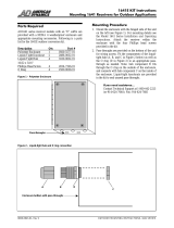
1. Remove the two #10 hex head screws from the back of
the enclosure and attach mounting bracket to enclosure.
2. Select the proper location for the control panel and hang
enclosure on a flat vertical surface or other support. When
mounting the enclosure, be sure to use hardware capable
of supporting its weight.
NOTE: The main feed may enter through any one of the
1-3/4 inch knockouts at the bottom or back of the
enclosure. A dimple is positioned on the top of the
enc
losure for piloting a drill to create an overhead
entrance into the panel. The main feed must also pass
through a listed outdoor conduit hub, mounted at the time
of installation.
3. Prepare the necessary conduit runs, terminate them at both
ends and pull in the conductors as specified by the
installation layout.
*If this control is to be used for direct connection
to under-water lights, a Nonmetallic Hub Kit shall be used.
Order 156PA13713A for a 1/2” Kit, 156PA13714A for a
3/4” Kit or 156PA13715A for a 1” Kit.
4. Refer to Figure 1 below.
Note that though this figure
shows a P1353ME Digital
Time Clock installed, the
P1353ME is not included on
all models. See door panel for the specific configuration
and rating of the model you are installing. A breaker base
for up to four full size circuit breakers is included on all
models. To wire the panel, follow the wiring diagram
loca
ted inside the enclosure door. When the P1353ME,
make sure that the connections are tight (25 lb.-in.
minimum) and
insulation clears the pressure plate
(see illustration).
5. If r
equired by the heater manufacturer, the P1353ME
includes a connection for a fire-man switch. This switch
only works in conjunction with circuit #1 (Load #1) on
the P1353ME. Refer to pages 6 & 7 of the instruction
manual f
or connection inf
ormation, and refer to page 28
for fireman switch programming information. Use at least
#18 AWG wiring with insulation rated 300 volt or higher.
Some heaters may require a special connecting harness,
contact heater manufacturer for details. Place heater
ON/OFF switch on heater to ON position.
6. To install additional wiring devices inside the enclosure,
first remove rectangular knockout(s) in dead front. Next,
remove hex head screws in back of enclosure and install
stand-offs* in place of screws. Attach wiring device to
stand-offs.
*
Stand-offs are not furnished. Order 21T156A for a set of
four (4) stand-offs and mounting hardware.
7. If external bonding is required, install a bonding lug at
bottom of enclosure and bond installation according to
code requirements (Order 156T11047A for Bonding
Lug Kit).
8. Testing of the installation is optional and recommended
only if the desired loads are securely in place and will not
be damaged by this test:
a. Turn ON power at breaker panel.
b. P1353ME display should fully illuminate and then start
to blink 12:00 a.m. Time clock will not blink only if time
has been maintained by internal battery.
c. Push each of the ON/OFF buttons to verify devices
cycle on and off. In case of unsatisfactory results, turn
OFF power, check your wiring, refer to Troubleshooting on
Page 3.
9. Install front panel over wiring compartment. The control
is now ready for programming, see OPERATION section
on Page 4.
2 3
IMPORTANT SAFETY INSTRUCTIONS
W
hen installing and operating this product and other associated equipment, basic safety precautions should always be followed,
including the following:
1. Read and follow all instructions.
2. This control must be installed by a qualified electrician, according to National and Local Electrical Codes.
3. Install this control not less than 5 feet (3 meters in Canada) from inside edge of pool. USE COPPER CONDUCTORS ONLY.
4. Do not exceed the maximum ratings of individual components, wiring devices, and current carrying capacity of conductors.
5. For control grounding, bonding, installing and the wiring of underwater lights, refer to Article 680 of the National Electrical
Code or Article 68 of the Canadian Electrical Code.
6
. This control should not operate any equipment which would cause bodily injury or property damage should it be activated unexpectedly.
READ, FOLLOW AND SAVE THIS INSTRUCTION MANUAL
PRESSURE PLATE
TERMINAL SCREW
MAKE SURE INSULATION
CLEARS PRESSURE PLATE
Figure 1
FLTR
PUMP
2
PUMP
1
HTR
SPA
JETS
A
IR
CLNR
LITE 1
LITE 2
HIGH
LOW
AUX 1
AUX 2
AUX 3
W/FA
External Wired Remote Accessory
Part Number 133PE1484A
(not included with all models)
The New Intermatic Wired Remote Control allows
you to control the P1353ME from a remote
location. Included with the Wired
Remote Control is a label arrangement
allowing you to identify each button
specific to your pool or spa equipment
pad. The new wired remote control
comes standard with 100 foot of cable
and is designed to slip fit into any
standard 1 1/2” conduit adapter. This
remote works in conjunction with the
P1353ME and displa
ys feedback information on the
present state of the pool or spa equipment pad.
For mor
e infor
mation refer to instructions provided
with the accessor
y.
Freeze Probe Accessory
Part Number 178PA28A
(not included with all models)
The New Intermatic Freeze
Probe allows you to protect
your pool or spa equipment
during an unexpected freeze
condition. The freeze probe
comes with a 10 foot cable
and plugs into the back of the
new P1353ME. The P1353ME
can be programmed to turn on
each or all-individual loads at any desired
outside temperature.
Heater Protection (Fireman) Switch is
standard with each P1353ME.
It comes standard with a Fireman Switch
connection f
or your pool or spa heater.
Simply connect the two wires from the
hea
ter thermostat to the back of the
P1353ME.
The fireman switch is only
associated with circuit one on the
P1353ME, therefore the filter pump should
be connected to cir
cuit one
. Program the
time desired for the cool down period and
the P1353ME will take over.
For more details, refer to instruction
manual.