
Start-up Instructions
VB/VW 500/750/1000
Series 100/101
Before starting the boiler, please review the boilers instruction manual (AOS Part Number 212800) supplied with the boiler. This
is a powered combustion copper tube boiler. Please contact an authorized A.O. Smith representative before starting the unit.
Ensure that the water piping, gas line, controls, and venting have been installed per the instruction manual.
Gas supply lines should be sized in accordance with the current edition of National Fuel Gas Code (ANSI Z223.1/NFPA 54) or
CAN/CSA B149.1 The Canadian Natural Gas and Propane Installation Code.
Make sure the boiler is not damaged. If the unit is damaged, contact an A.O. Smith representative for service or replacement
parts prior to starting the boiler.
This boiler is equipped with a Modulating EMC 5000 control system. The EMC 5000 displays the system status and errors that may
occur during normal operation. For full details on the controls, please refer to the Installation Manual supplied with the boiler. The
boiler must be installed according to the instructions provided with the unit. Failure to do so will void the warranty.
The following test equipment should be on hand: (all test equipment must be acclimated to ambient temperature before calibration
and use.)
• AcombustionanalyzercapableofmeasuringCOandCO
2
or O
2
.
• Adigitalmanometerorpressuregaugescapableofaccuratelydisplaying0–15(±.01)inchesofwatercolumn.
• Combinationvolt/ammeter
• TORX®T40or5mmhexwrench–forsettinggasmixtureatgasvalve
• 3mmor7/64inhexwrench–forsettinggasmixtureatgasvalve
I. Verify utilities
• Ensurethatthewaterpiping,gasline,controls,andventinghavebeeninstalledpertheinstructionmanual.
• Becertainthatthesystemisfullofwater,thatairispurgedfromalllines,theboiler,andstoragetank.
• Ensurethatnoleaksarepresentandthatallsupplyandreturnwatervalvesareopen.
• Upstreamgasvalveshouldremaincloseduntilstartup.
II. Component Sequence Verication
• Ensurethatthepowersupplymeetstheserequirements:singlephase,Minimum:108VACRMS;Maximum:132VACRMS
and is on a dedicated circuit breaker with separate neutrals and grounds.
• Ensureallcontrolwiringisruninadedicatedconduitperinstructionmanual.
• Performpowersupplytestoutlinedintheinstructionmanual.
• Ensurethattheupstreammanualgasvalveoftheboilerisopen.
Priortoturningonthegas,propersequenceofmostofthesystemcanbeveried.Withthewaterturnedon,andthegasturned
off by the downstream manual valve, start the system and allow it to run through a heating cycle. It should stop when it checks for
theameanddeclareafault.Thiswillverifythatthepump,owswitch,igniter,variablefrequencydrive,modulatinggasvalve,
blower and low/ high blower prover switches are all functioning properly.
III. Initial Boiler Set-up Verication
• Drillamaximum7/16”holeinthesideoftheventbootteeapproximately8”frombackpaneltoinsertthegasanalyzerprobe.
The hole must be sealed upon completion of the start-up testing.
• Openthedownstreammanualgasvalvetotheboilerandpurgeairfromtheline.
PRINTED0608 212936-002

• Measuretheincominggaspressure.-Minimuminletgassupplypressureof4”w.c.andmaximumis11.0fornaturalgasor
8”w.c.minand13.8maxforpropane.Themaximumvaluespeciedmustnotbeexceededunderbothloadandnoload
conditions.Ifthisconditioncannotbeobtainedapositivelock-uptypepressureregulatorMUSTbeinstalledapproximately
vefeetawayfromthegasvalveoftheboilerandpertheregulatormanufacture’sinstructions.
• Checkallgassupplylinesforleaks.
• Checkthatallventingisproperlyinstalledinaccordancewiththeventingsectionoftheinstructionmanual.
Follow the lighting and operating instructions in the Instruction Manual.
IV. Boiler Start-Up
• Starting the boiler for the rst time
-Theboileristestedatthefactoryandshouldstartproperlyifinstalledinaccordancewiththeboiler’sinstructionmanual.
- Before starting the boiler, refer to the temperature set-point procedure section in the boilers instruction manual.
-Turnontheboiler’son/offswitch.Ensuretheoperatingsetpointissethighenoughtoactivateacallforheat.Ifanexternal
controlisusingtheboiler’sEnable/Disablecircuit,ensurethattheexternalcontrol’scontactsareclosed.Ifthereisno
externalcontrol,ensurethatthetwowiresprovidedforthiscircuitarewire-nuttedtogetherinthejunctionboxontheback
oftheboiler.Refertothewiringdiagramontheboiler.
- Allow the unit to run for at least 10 minutes before proceeding with the combustion analysis. Take a combustion sample and
record CO and CO
2
or O
2
readings.
• Setting of the test mode
-OnUIMgotomainmenu,scrolldowntousersettingsandpressselect.ScrolldowntoMODmode,pressselect.Use
theupanddownkeystoselectoptions:MIN(MINIMUMFIRINGRATE).MAX(MAXIMUMFIRINGRATE).MOD(FOR
AUTOMATICMODULATIONMODE).Pressselectforthedesiredoption.ForcheckingthecombustionsetuponMINor
MAXtheboilerwillremaininthisstatefor20minutesbeforedefaultingtotheMOD(modulation)mode.
• MAXIMUM FIRE ADJUSTMENT
- Combustion sample
-Firstsetboilertothe“TestModeMax,”asdescribedabove,toachievemaximumringrateoftheboiler.Checkcombustion
readingsusingacombustionanalyzer.Ifcombustionreadingsarenotinaccordancewiththechartbelowadjustasfollows:remove
theat,round,blueplasticcapfromthecover.Usinga3mm(7/64”)hexwrench,turntheadjustmentscrewcounterclockwiseto
increaseorclockwisetodecreasegasowandachievethedesiredCO
2
level. See Table referenced below for correct settings.
TherewillbeaslighttimedelaybetweentheadjustmentandtheresponseoftheCO
2
measuringinstrument.Adjustthesettings
insmall1/16incrementsandallowthecombustionreadingstostabilizebeforereadjusting.Whendesiredadjustmentsare
complete, reinstall the blue plastic cap on the cover. Combustion samples shall be taken within 8 inches from the rear boiler.
IMPROPERADJUSTMENTCANCAUSEINCOMPLETECOMBUSTIONRESULTINGINDEATH.
• MINIMUM FIRE ADJUSTMENT - Combustion sample
-Nextsetboilertothe“TestModeMin,”asdescribedabove,toachieveminimumringrateoftheboiler.Checkcombustion
readingsusingacombustionanalyzer.Ifcombustionreadingsarenotinaccordancewiththechartshownbelowadjustas
follows:removethemetalcaponthegasregulatorusingaslottedscrewdriver.Thiswillexposetheoffsetadjustmentscrew.
UsingaTORX®T40ora5mmhexwrench,carefullyadjustthelowregassettingtoachievetheCO
2
level prescribed
inbelowreferencetable.Note:TherotationoftheLowFireadjustmentisoppositeoftheHighFireasfollows:Clockwise
rotationincreasesgasow,counterclockwiserotationdecreasesgasow.Adjustmentstotheoffsetpressureregulators
shouldnotexceed1/16incrementsatatimebeforeallowingthereadingstorespondandstabilize.Afterproperlowre
offsetadjustmentismade,reinstalltheslottedcapontheregulator.
Followingallgasvalveadjustments,checkforproperlight-offandverifycorrectfuel/airmixduringtestmodeprocedureprescribedabove.
Ifadjustmentshavebeenmade,repeatthecombustionsamplingusingthe“TestMode”proceduretoinsurethatthereadingsremain
withintheranges.IfthereadingsarenotinaccordancerepeattheHighandLowreadjustmentprocedure.
IMPORTANT!! The Min Mode and Max Mode are used for checking combustion during start up. Return boiler to Mod Mode after
checking combustion.
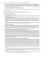
• Combustion readings should fall within the ranges listed in the table below.
Combustion Samples Acceptable Range
% CO
2
, for Natural Gas @ max input 8.0% - 9.5%
% CO
2
, for Propane Gas @ max input 8.5% - 10.0%
CO PPM < 200 PPM
% CO
2
, for Natural Gas @ min input 6.5%-7.5%
% CO
2
, for Propane Gas @ min input 7.5%-8.5%
CO PPM < 100 PPM

• Ifcombustionmeasurementsarenotintherangespecied,pleaserepeattheSettingofthetestmodeandMaximumand
Minimumreadjustmentprocedureasdescribedpreviously.
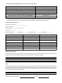
Start Up Record
Start-upDate______________________
ModelNumber_____________________
SeriesNumber______________________
Gastype:___________
Powersupplyvoltage:Hot/Gnd______VAC,Hot/Neutral______VAC,Neutral/Gnd______VAC
Maximum Fire Minimum Fire
InletGasSupplyPressureInchW.C.
ManifoldPressureInchW.C.
CO
2
%
CO PPM
O
2
%
BlowerRPMs
Flue Gas Temp (°F)
StackPressureInchW.C.
DISPOSITION
AlltestsandvaluesspeciedmustmeetspecicationspriortoissuingthisStart-upcerticate.Foranydiscrepancies,please
explainbelowwhatactionwastakentocorrecttheproblem.
NOTIFICATION
Alltestandvaluesspeciedmustmeetspecicationspriortoissuingthisstart-upcerticate.Foranyoftheeldtestsperformed,
explainbelowwhatactionwasperformedtocorrecttheproblem.Theownerhasbeennotiedthatcorrectionsmustbemadeto
this installation. The owner acknowledges that changes must be made within 30 days, prior to start up being completed.
RequiredSignatureofOwner Date

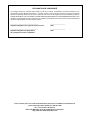
STATEMENT OF COMPLIANCE
I, the undersigned, certify that the product listed and described above has been started in accordance with this
form and the literature provided, (Instruction Manual part number 212800) and that all measured values and
requirementsarewithin the manufacturer’s specications. If thisunit does not meet all start-upcriteriain this
document, DO NOT LEAVE UNIT IN OPERATION. SEVERE PERSONAL INJURY, PROPERTY DAMAGE OR
EQUIPMENTDAMAGEMAYOCCUR.Iftheboilerisdamagedduetoanycriterianotbeingmet,WARRANTYmay
not cover damaged parts or any labor allowances.
__________________________________ __________________
Required Signature of Start-up Agent Date
__________________________________ __________________
Required Signature of Owner, contractor or installer Date
For additional information please refer to the User’s Manual supplied with the boiler or contact:
A.O. Smith Technical Services at 1-800-527-1953
7 a.m. to 7 p.m. Central Time
Our Internet Site is another source of information 24 hours a day.
http://www.aosmithwaterheaters.com
Page is loading ...
Page is loading ...
Page is loading ...
Page is loading ...
-
 1
1
-
 2
2
-
 3
3
-
 4
4
-
 5
5
-
 6
6
-
 7
7
-
 8
8


A.O. Smith VB 750 Quick start guide
- Type
- Quick start guide
- This manual is also suitable for
Ask a question and I''ll find the answer in the document
Finding information in a document is now easier with AI
in other languages
Related papers
Other documents
-
Vulcan K60GLT Owner's manual
-
Dunkirk DCC/DCB High Efficiency Wall Mounted Modulating Condensing Boiler Installation & Operation Manual
-
-
-
-
TRIANGLE TUBE EB073 User manual
-
Baxi LUNA HT 1.650 Installation And Servicing Instructions
-
UTICA BOILERS Cub Installation, Operation & Maintenance Manual
-
Baxi 804 Datasheet
-