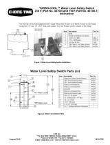
In the back of the Sump tank drill a 9/32” hole, 3-1/2” [89mm] straight above the existing
mounting hole in the Sump, on the side of the Sump opposite the Trough (See Figure 1. below).
Both possible mounting locations are shown, but only drill the hole on the side of the sump
opposite the Trough. Mount the Water Level Safety Switch to the Sump using the 1/4” nut,
1/4 x 5/8” bolt, and washer. Use the Washer on the outside of the Sump.
Water Level Safety Switch Parts List
TURBO-COOL™ Water Level Safety Switch 230V
(Part No. 46700), and 120V (Part No. 46700-1)
Instruction
Mv1679-001 04/01
2
4
3
1
567
8
Figure 1. Water Level Safety Switch Installation
Item Description Part No.
1 Sump --
2 Switch mounting hole locations --
3 Existing mounting holes --
4 3-1/2” [89mm] --
5 1/4-20 x 5/8 Bolt 4404-7
6 .275 x 1.00 Washer 2955-52
7 1/4” Hex SS Nut 7145
8 230V Water Level Safety Switch
120V Water Level Safety Switch
46700
46700-1
1
2
3
4
5
6
5
7
8
9
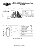
"On" Water Level
"Off" Water Level
10
11
12
13
Mv1679-003 04/01
Item Description Part No.
1 Water level Safety Switch Bracket 46708
2 230V Cord Switch Housing
120V Cord Switch Housing
46701
46701-1
3 Water Level Switch Pin 46704
4 Water Level Switch Rod 46702
5 Grommet 46709
6 Water Level Switch Float 46703
7 Water Level Switch Screw 46706
8 #10 x 1/2 SS Screw 38613
9 3.5” [89mm] OD x 10” Pipe 46707
10 2-1/2” [64mm] --
11 7-5/8” [193mm] --
12 11-11/16” [297mm] --
13 5-1/2” [140mm] Between Grommets --
Figure 2. Water Level Switch Parts
Chore-Time Equipment a Division of CTB Inc.
P.O. Box 2000 • Milford, Indiana 46542-2000 • U.S.A.
Phone (574) 658-4101 • Fax (877) 730-8825
E-Mail: [email protected] • Internet: http//www.ctbinc.com
MV1679BNovember 2002

TURBO-COOL™ Water Level Safety Switch 230V (Part No. 46700), and 120V (Part No. 46700-1) Instruction
2
MV1679B
Switch Specifications
50/60Hz single phase.
Maximum Pump Running Current: 13 amps.
Maximum Pump Starting Current: 60 amps.
Recommended Pump HP for: 230V Switch-1HP or less, 120V Switch-1/2HP or less.
This Switch must be used with Pumps that provide integral thermal overload protection.
Failure to follow the above precautions could result in serious injury or death. Replace product
immediately if switch cable becomes damaged or severed. Keep these instructions after
installation. This product must be installed in accordance with National Electric Code, ANSI/
NFPA 70 so as to prevent moisture from entering or accumulating within boxes, conduit
bodies, fittings, float housing, or cable
Switch Wiring Options
Wire Switch as shown in Figure 3. below.
Check installation. Allow system to cycle to insure proper operation.
Mv1679-006 04/01
ELECTRICAL SHOCK HAZARD
Disconnect power before installing or servicing this
product. A qualified service person must install and service
this product according to applicable electrical plumbing
codes.
Mv1679-007 04/01
EXPLOSION OR FIRE HAZARD
Do not use this product with flammable liquids.
Do not install in hazardous locations as defined by National
Electrical Code, ANSI/NFPA 70.
In 230 VAC Pump installations, one side of the line going
to the Pump is always HOT. This conditions exists if the
Switch is on or off. Install double pole disconnect on all 230
VAC Pump circuits.
G
G
L2
L2
L1
L1
G
Black
White
Liquid-Tight
Connector
230V
Power
Source
230V
Pump
Switch
Junction
Box
Mv1679-005 06/02
Switch
Plug
Pump
Plug
230 V Outlet
230V Piggy-back Installation
230V Direct Wire Installation
G
G
N
N
L1
L1
G
Black
White
Liquid-Tight
Connector
120V
Power
Source
120V
Pump
Switch
Junction
Box
120V Direct Wire Installation
Switch
Plug
Pump
Plug
120V Outlet
120V Piggy-back Installation
Figure 3. Switch Wiring Diagram
/