Page is loading ...

12039 Smith Ave.
Santa Fe Springs CA 90670
USA / 1-877-338-0999
www.championpowerequipment.com
SAVE THESE INSTRUCTIONS
Important Safety Instructions
are included in this manual.
MADE IN CHINA
REV 100189-20160225
100189
MODEL NUMBER
OWNER’S MANUAL & OPERATING INSTRUCTIONS
/
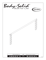
BIKE CARRIER

Have questions or need assistance?
Do not return this product to the store!
WE ARE HERE TO HELP!
Visit our website:
www.championpowerequipment.com
for more info:
• Product Info & Updates
• Frequently Asked Questions
• Tech Bulletins
• Product Registration
– or –
Call our Customer Care Team Toll-Free at:
1-877-338-0999
*We are always working to improve our products. Therefore, the enclosed product may differ slightly from the image on the cover.
Parts Ordering:
Mon – Fri 8:30 AM – 5:00 PM (PST/PDT)
Toll Free: 1-877-338-0999

100189
TABLE OF CONTENTS
Introduction ............................ 4
Introduction .......................... 4
Manual Conventions ....................... 5
Safety Rules ............................ 6
Controls and Features ..................... 7
Bike Carrier .......................... 7
Parts Included ........................ 8
Assembly .............................. 9
Assembling the Bike Carrier ............... 9
Mounting the bikes .................... 11
Tilt Down Feature ..................... 12
Travel/Storage Feature .................. 12
Parts Diagram .......................... 14
Parts List ............................. 15
BIKE CARRIER

4
ENGLISH 100189
INTRODUCTION
Record the model and serial numbers as well as date and place of purchase for future reference. Have this
information available when ordering parts and when making technical or warranty inquiries.
Champion Power Equipment Support
Model Number
Date of Purchase
Purchase Location
1-877-338-0999
100189
Introduction
Congratulations on your purchase of a Champion Power Equipment product. Champion Power Equipment and
Champion Engine Technology designs, builds, and supports all of our products to strict specifications and guidelines.
With proper product knowledge, safe use, and regular maintenance, this product should bring years of satisfying
service.
Every effort has been made to ensure the accuracy and completeness of the information in this manual, and we
reserve the right to change, alter and/or improve the product and this document at any time without prior notice.
Since CPE/CET highly value how our products are designed, manufactured, operated and are serviced, and also
highly value your safety and the safety of others, we would like you to take the time to review this product manual
and other product materials thoroughly and be fully aware and knowledgeable of the assembly, operation, dangers
and maintenance of the product before use. Fully familiarize yourself, and make sure others who plan on operating
the product fully familiarize themselves too, with the proper safety and operation procedures before each use. Please
always exercise common sense and always error on the side of caution when operating the product to ensure no
accidents, property damage, or injury occurs. We want you to continue to use and be satisfied with your CPE/CET
product for years to come.

5
100189 ENGLISH
This manual uses the following symbols to help differentiate between different kinds of information. The safety symbol
is used with a key word to alert you to potential hazards in operating and owning power equipment.
Follow all safety messages to avoid or reduce the risk of serious injury or death.
CAUTION indicates a potentially hazardous
situation which, if not avoided, may result in minor
or moderate injury.
CAUTION
CAUTION used without the safety alert symbol
indicates a potentially hazardous situation which, if
not avoided, may result in property damage.
CAUTION
DANGER indicates an imminently hazardous
situation which, if not avoided, will result in death
or serious injury.
DANGER
WARNING indicates a potentially hazardous
situation which, if not avoided, could result in
death or serious injury.
WARNING
If you have questions regarding your bike carrier, we
can help. Please call our help line at 1-877-338-0999.
NOTE
MANUAL CONVENTIONS

6
ENGLISH 100189
SAFETY RULES
ALWAYS secure your bicycles to the rack using the
frame cradles and straps. Additional rope, shock
cords, or cable locks may be used for additional
security and stability.
If a strap appears worn or frayed, replace it
immediately.
Check straps and cradles regularly during use. It’s a
good practice to stop your vehicle after 152 m
(500 ft.) and check the security of the mounted
bicycles.
This bike carrier was not constructed to protect
bicycles from severe abuse in off-highway driving
conditions. Bumpy roads may cause mounted
bicycles to move and shift in transit, resulting in
property damage.
DO NOT let bicycle tires hang near the exhaust pipe of
your vehicle. Hot exhaust may cause damage to tires.
CAUTION
Read this manual thoroughly before installing and
using your bike carrier. Failure to follow instructions
could result in serious injury to person or property.
WARNING
This rack is designed to attach securely to most
automobile receiver hitches. Due to variations
in automobile design and utility, we cannot
guarantee this product will fit all vehicles. It is your
responsibility to ensure the safe and proper use of
this product.
This rack is designed for use on passenger cars,
trucks and SUVs with appropriate receiver capacity.
Improper use and attachment of the rack to your
vehicle may be hazardous to your bicycles, vehicles
or other vehicles driving behind you.
WARNING
DO NOT exceed the rated capacity of this bike
carrier. Load no more than 4 bicycles, weighing less
than 68 kg (150 lb.) total.
DO NOT use this bike carrier for transporting or
carrying other items or materials besides bicycles.
WARNING
The bicycle carrier should not be used for TOWING
or any pulling purpose. Not for use behind a 5th
wheel, travel trailer, or motor home.
WARNING
Not for use on the back of
trailers and motor homes,
or on off-road terrain.

7
100189 ENGLISH
CONTROLS AND FEATURES
Read this owner’s manual before using your bike rack. Familiarize yourself with the location and function of the
controls and features. Save this manual for future reference.
Bike Carrier
(1) Cradle – Used to support wheels.
(2) Hooks – Used to secure bike frame.
(3) Wing nut – Used to slide arms in place to fit
wheels.
(4) Extension tube – Used to convert from a 2 to a 4
bike carrier.
(5) Plastic knob – Used to adjust height of hooks.
(6) 5.1 cm (2 in.) Adapter – Used to adapt 3.2 cm
(1.25 in.) hitches to 5.1 cm (2 in.)
(7) Wheel straps – Used to secure wheels on the
cradles.
(8) Reflector
1
2
7
3
4
8
5
6

8
ENGLISH 100189
CONTROLS AND FEATURES
Parts included
Your 100189 bike carrier ships with the following parts:
Assembly parts
A. Support base assembly ...................2
B. Left cradle assembly .....................4
C. Right cradle arm assembly .................4
D. Hitch mounting shank assembly .............1
E. Long J-hook assembly ....................2
F. Short J-hook assembly ....................2
G. Extension tube .........................1
H. Horizontal tube .........................2
I. Strap ................................8
J. Screw M12 x 70 with end hole ..............2
K. Flat washer Ø13 ........................3
L. Flat washer Ø10 ........................7
M. R-pin ................................ 3
N. Cap screw M10x60 ......................4
O. Plastic spacer Ø15 x Ø28 ..................8
P. Lock nut M10 ..........................4
Q. Screw M12 x 80 ........................1
R. Plastic spacer Ø15 x Ø36 ..................4
S. Lock nut M12 ..........................1
T. Screw M12 x 95 with end hole ..............1
U. Screw M6 x 10 .........................4
V. Allen wrench M5 ........................1
W. Metric wrench 17-18-19 ...................2
X. Reflector .............................2
Y. Flat washer Ø15 x Ø28 ...................4
A B C D
E
F
G H I
J
K
K
L
L
L
M
M
N
O
P
Q
R
S
T
U
V
W
X
Y
QT Y. QT Y.
Assembly parts

9
100189 ENGLISH
ASSEMBLY
Grease can be applied to the plastic spacers if needed
for grip upon reinsertion of hardware and tube.
NOTE
Assemble the primary (1-2 bike) frame, by taking the
support base assembly (A) and connecting the horizontal
tube (H) using two cap screws (N), lock nuts (P), flat
washers (L), and four plastic spacers (O). Make sure
the bolt on the end of the horizontal tube is facing up.
Be sure to re-insert the two (2) plastic spacers inside
of support base before inserting square horizontal tube.
Align two small pins into the holes provided.
Attach the primary (1-2 bike) support base assembly to
hitch mounting assembly (D). Be sure to insert plastic
spacers (R) into square tube before attaching to hitch
mounting assembly using screw M12x80 (Q) and lock nut
M12 (S). Use metal strap and pin Ø8 x 85 mm and pin
Ø12.6 x 8 mm for extra safety.
Assembling the bike carrier cont’d.
Assembling the Bike Carrier
Remove hardware already in the support base prior to
any assembly or inserting tube.
NOTE
1. The primary support base frame will NOT have a
reflector at the end of the tube.
NOTE
2. Insert plastic spacers (2) onto each side of square
tube prior to assembly to hitch mounting assembly
assembly.
NOTE
1
H
2
Make sure the centre bar is in the upright and locked
position. Slide the notched key slide into the centre hole
and turn to ensure it’s locked. Using your hand or a
phillips head screw driver (not included), unscrew the bolt
on the ends of the horizontal tubes.
1
2
3
4
Slide the wheel cradles (B+C) onto the horizontal tubes
(A+H). Adjustment knob should be facing up. Loop end
of cradle should be facing outward and upward. Insert
cradles in sequence as shown below. After all 4 cradles
are on the horizontal tubes, replace the end bolts and
tighten using a phillips head screwdriver (not included).

10
ENGLISH 100189
ASSEMBLY
If transporting 3 or 4 bicycles, build the secondary bike
frame the same as the primary (1-2) bike frame. Then
attach the secondary bike frame assembly to the main
hitch assembly using the extension tube (G).
Assembling the bike carrier cont’d. Assembling the bike carrier cont’d.
Install long J-hook assembly (E) and short J-hook
assembly (F) onto the centre bar. Twist the side knobs to
untighten/tighten and allow the J-hooks to slide up and
down the centre bar.
3. When tightening “J-hooks” make sure there is
no gap in the bottom adjuster. The bottom knob
adjuster is ”spring” loaded and must be tightened all
the way to ensure safety.
NOTE
J-hooks must NOT slide all the way down on the
centre bar. This will prevent the bar from going all
the way down on either side and locking for proper
storage.
WARNING
If only using the primary (1-2) bike frame, ensure a
reflector (X) is inserted firmly into the hollow end before
street/road use. Do not insert if using the 3-4 bike frame.
3
3
First attach the extension tube (G) to the primary bike
frame, using screw M12x70 with end hole (J), flat washer
Ø13, flat washer Ø10 (K, L) & R-pin (M).
Then attach the secondary frame to the extension tube
using the plastic spacers (R) into square tube before
threading through screw M12x70 with end hole (J) flat
washer Ø13, flat washer Ø10 (K, L) & R-pin (M). Tighten
securely.

11
100189 ENGLISH
MOUNTING
If you are mounting to a 3.6 cm (1 1/4 in.) receiver hitch,
remove the hex socket screw connecting the 5.1 cm (2 in.)
receiver adapter, with the allen wrench provided.
The wheel cradles and J-hooks are completely adjustable
and slide on the tubes. Using the vertical knobs on
the tops of the cradles and the horizontal knobs on the
J-hooks, twist them unit they are loose and the cradle or
J-hook can move on the tube.
Mounting the Bike Carrier Mounting the bikes
Remove any debris to ensure no blockage is in the
receiver.
NOTE
After removal of the 5.1 cm (2 in.) receiver adapter,
connect the bike carrier using the screw M12x95 mm with
end hole and washers and R-Pin.
If you are mounting to a 5.1 cm (2 in.) receiver then mount
the bike carrier using the using the 5.1 cm (2 in.) receiver
adapter, screw M12x95 mm with end hole and washers
and R-Pin.
Once adjusted to allow the bike to properly fit into the
cradles, load the bike wheels directly into the cradles and
ensure they will not roll back and forth. Bring down the
J-hook till it is snuggly fit over the middle part of the frame
on the bike. Twist the side knob to secure the position
of the J-hook. Use the strap on the cradles to secure the
wheels. Adjust the strap as needed per each wheel. Make
sure all wheels have a strap securing them.
Drive for a short amount, stop inspect that the
bikes are still securely mounted.Always inspect all
mounting hardware before use or mounting.
NOTE

12
ENGLISH 100189
For access to the rear of vehicle, with the bikes removed
from the rack, securely grasp bike rack, remove main
locking pin (through centre of tube) (A), while continuing
to grasp the rack, remove the back-up pin (under main bar)
(B), and allow the rack to tilt downward. DO NOT drop or
allow the rack to be unsupported while the pins are out,
this may damage the rack and/or cause injury.
When traveling without bicycles, the bike carrier can fold in
the upright position. With the bikes removed from the rack,
twist and remove the locking pin from the centre hole. Fold
the main centre bar to horizontal position (down on either
side) and re-secure using locking pin. Securely grasp bike
rack, remove main locking pin (through centre of tube), lift
the rack to the upright position and re-secure locking pin to
hold in upright position.
Tilt Down Feature Travel / Storage Feature
MOUNTING
B
A
DO NOT attempt to pull out the main locking pin or
back-up locking pin while there are bikes mounted
to the carrier.
WARNING
Failure to properly insert and twist locking pin can
cause damage to bikes, vehicles and possibly cause
injury.
WARNING
When traveling, the bike carrier must be locked in
the horizontal or upright position. DO NOT operate
the vehicle if the carrier is not locked into place.
CAUTION
The bike carrier can be put in the upright position
with the secondary (3-4) bike carrier attachment
installed.
NOTE

13
100189 ENGLISH
MOUNTING
This Page Intentionally Left Blank.

14
ENGLISH 100189
SPECIFICATIONS
Parts Diagram
46
34
35
36
8
10
9
33
37
38
39
40
41
42
43
44
45
1
2
3
4
5
7
31
10
12
11
13
14
18
19
21
20
32
6
9
8
13
12
11
22
14
22
18
30
23
23
23
23
25
26
27
27
28
29
29
24
25
13
13
19
13
14
17
16
12
11
21
20
11
13
12
31
32
3
4
21
6
15
16
17
17
15
16
14
14
15
14
14
15
16
17
24
14
2
3
4
47
7
31
10
12
11
13
14
18
19
21
20
32
6
9
8
13
12
11
22
14
22
18
30
23
23
23
23
25
26
27
27
28
29
29
24
25
13
13
19
13
14
17
16
12
11
21
20
11
13
12
31
32
3
4
21
6
15
16
17
17
15
16
14
14
15
14
14
15
16
17
24
14

15
100189 ENGLISH
SPECIFICATIONS
# Part Number Description Qty
1
100189 -17 REFLECTOR 2
2
100189 -13 PIN Ø9 2
3
GB/T12-85 (M10 x 60) CAP SCREW M10 x 60 mm 10
4
GB/T97-2000 (Ø15 x
Ø28)
FLAT WASHER Ø15 x Ø28 mm 10
5
100189-03A SUPPORT BASE-REAR 1
6
100189 -16 PLASTIC SPACER Ø15 x Ø28 20
7
100189-11
SCREW M12 x 70 mm WITH
END HOLE
2
8
GB/T97-2000 (Ø13) FLAT WASHER Ø13 mm 3
9
GB/T97-2000 (Ø10 x 2) FLAT WASHER Ø10 x 2 mm 3
10
100189 -19 R PIN 3
11
100189-06.2 ROUND PLUG Ø28 mm 8
12
100189 -12 STRAP 8
13
GB/T12-85 (M8 x 70) CAP SCREW M8 x 70 mm 12
14
100189-06.4 PLASTIC ADAPTOR 24
15
GB/T97-2000 (Ø8) FLAT WASHER Ø8 mm 16
16
GB/T93-1987 (Ø8) SPRING WASHER Ø8 mm 12
17
100189-06.5 SMALL WING NUT 8
18
10 018 9 - 07.1 LEFT SUPPORT ARM 4
19
100189- 05.1 HORIZONTAL TUBE 4
20
GB/ T1818-2000 (M6
x 10)
SCREW M6 x 10 mm 4
21
100189-04.2
SQUARE PLUG, 32 x 32 mm,
EDGE 2.5 mm
6
22
100189- 06.1 RIGHT SUPPORT ARM 4
23
100189-18 BIG WING NUT 8
# Part Number Description Qty
24
100189-08.2 SPRING 4
25
100189-08.3 HOOK BASE 4
26
100189- 08.1 LONG HOOK 2
27
100189-08.5 HOOK SLEEVE 4
28
100189- 09.1 SHORT HOOK 2
29
100189-08.4 ROUND PLUG Ø16 mm 4
30
100189- 04.1 VERTICAL TUBE 2
31
GB889-86 (M10) LOCK NUT M10 10
32
GB/T97-2000 (Ø10) FLAT WASHER Ø10 mm 10
33
100189-10 EXTENSION TUBE 1
34
100189-01.2 PIN Ø8 x 85 mm 1
35
10189-01.6 SCREW M8 x 75 mm 1
36
100189-01.3 PIN Ø12.6 x 8 mm 1
37
100189-01.4 RING 1
38
100189 -14 SCREW M12 x 80 mm 1
39
100189-02
SCREW M12 x 95 mm WITH
END HOLE
1
40
100189 -1.1 HITCH MOUNTING SHANK 1
41
100189-01.5 2 in. RECEIVER ADAPTOR 1
42
GB5782-2000 (M6 x
18)
HEX SOCKET SCREW M6 x
18 mm
1
43
100189-01.7
SQUARE PLUG, 32 x 32 mm,
EDGE 4.5 mm
1
44
GB889-86 (M12) LOCK NUT M12 1
45
GB889-86 (M8) LOCK NUT M8 1
46
100189 -15
PLASTIC SPACER
Ø15 x Ø36 mm
4
47
100189-03B SUPPORT BASE-FRONT
1

WARRANTY
CHAMPION POWER EQUIPMENT
2 YEAR LIMITED WARRANTY
Warranty Qualifications
Champion Power Equipment (CPE) will register this warranty upon
receipt of your Warranty Registration Card and a copy of your sales
receipt from one of CPE’s retail locations as proof of purchase.
Please submit your warranty registration and your proof of purchase
within ten (10) days of the date of purchase.
Repair/Replacement Warranty
CPE warrants to the original purchaser that the mechanical and
electrical components will be free of defects in material and
workmanship for a period of two years (parts and labor) from
the original date of purchase and 180 days (parts and labor) for
commercial and industrial use). Transportation charges on product
submitted for repair or replacement under this warranty are the sole
responsibility of the purchaser. This warranty only applies to the
original purchaser and is not transferable.
Do Not Return The Unit To The Place Of Purchase
Contact CPE’s Technical Service and CPE will troubleshoot any issue
via phone or e-mail. If the problem is not corrected by this method,
CPE will, at its option, authorize evaluation, repair or replacement
of the defective part or component at a CPE Service Center. CPE
will provide you with a case number for warranty service. Please
keep it for future reference. Repairs or replacements without prior
authorization, or at an unauthorized repair facility, will not be covered
by this warranty.
Warranty Exclusions
This warranty does not cover the following repairs and equipment:
Normal Wear
Products with mechanical and electrical components need periodic
parts and service to perform well. This warranty does not cover repair
when normal use has exhausted the life of a part or the equipment as a
whole.
Installation, Use and Maintenance
This warranty will not apply to parts and/or labor if the product is
deemed to have been misused, neglected, involved in an accident,
abused, loaded beyond the product’s limits, modified, installed
improperly or connected incorrectly to any electrical component.
Normal maintenance is not covered by this warranty and is not
required to be performed at a facility or by a person authorized by
CPE.
Other Exclusions
This warranty excludes:
– Cosmetic defects such as paint, decals, etc.
– Wear items such as filter elements, o-rings, etc.
– Accessory parts such as starting batteries, and storage covers.
– Failures due to acts of God and other force majeure events
beyond the manufacturer’s control.
– Problems caused by parts that are not original Champion Power
Equipment parts.
Limits of Implied Warranty and Consequential Damage
Champion Power Equipment disclaims any obligation to cover
any loss of time, use of this product, freight, or any incidental
or consequential claim by anyone from using this product. THIS
WARRANTY IS IN LIEU OF ALL OTHER WARRANTIES, EXPRESS
OR IMPLIED, INCLUDING WARRANTIES OF MERCHANTABILITY OR
FITNESS FOR A PARTICULAR PURPOSE.
A unit provided as an exchange will be subject to the warranty of the
original unit. The length of the warranty governing the exchanged
unit will remain calculated by reference to the purchase date of the
original unit.
This warranty gives you certain legal rights which may change from
state to state or province to province. Your state or province may also
have other rights you may be entitled to that are not listed within this
warranty.
Contact Information
Address
Champion Power Equipment, Inc.
Customer Service
12039 Smith Ave.
Santa Fe Springs, CA 90670 USA
www.championpowerequipment.com
Customer Service
Mon – Fri 8:30 AM – 5:00 PM (PST/PDT)
Toll Free: 1-877-338-0999
info@championpowerequipment.com
Fax no.: 1-562-236-9429
Technical Service
Mon – Fri 8:30 AM – 5:00 PM (PST/PDT)
Toll Free: 1-877-338-0999
tech@championpowerequipment.com
24/7 Tech Support: 1-562-204-1188
WARRANTY
/