Page is loading ...

Crestron PMK-17L
Pre-Construction Mount Kit
Installation Guide

This document was prepared and written by the Technical Documentation department at:
Crestron Electronics, Inc.
15 Volvo Drive
Rockleigh, NJ 07647
1-888-CRESTRON
All brand names, product names and trademarks are the property of their respective owners.
©2005 Crestron Electronics, Inc.

Crestron PMK-17L Pre-Construction Mount Kit
Pre-Construction Mount Kit:
PMK-17L
Description
The PMK-17L is a pre-construction mount kit for the Crestron Isys
®
TPS-17L wall
mounted touchpanel. The PMK-17L can also be used with the Isys i/O™
TPMC-17-CH-L and TPMC-17-QM-L wall mounted touchpanels. The PMK-17L is
used for installation on two studs with a 16¼-inch (minimum) space between the
studs. For custom touchpanel placement in a lectern, use the WMKT-17L. The
PMK-17L includes an 18 AWG bus wire to secure touchpanel cabling prior to
drywall installation and to avoid damaging the cables when the opening is routed.
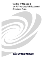
Refer to the physical views (bottom, side, and front) of the PMK-17L, shown after
this paragraph. The table that follows lists all parts included with the PMK-17L.
NOTE: This mounting kit is to be used only with the TPS-17L, TPMC-17-CH-L,
and TPMC-17-QM-L series of touchpanels.
PMK-17L Physical Views
16.40 in
(41.64 cm)
13.56 in
(34.44 cm)
0.03 in
(0.08 cm)
0.06 in
(0.15 cm)
16.00 in
(40.64 cm)
(PROVIDED BY OTHER)
FOR DRYWALL NAIL
(PROVIDED BY OTHER)
FOR DRYWALL SCREW
CUTTING TOOLS.
AWAY FROM DRYWALL
IN NOTCH TO HANG CABLES
SECURE 18 AWG BUS WIRE
19.00 in
(48.26 cm)
PRE-CONSTRUCTION PLATE COVER PLATE
Installation Guide - DOC. 6368 Pre-Construction Mount Kit: PMK-17L • 1

Pre-Construction Mount Kit Crestron PMK-17L
Supplied Components
DESCRIPTION PART NUMBER QUANTITY
Metal, Plate, Mounting 2013468 1
Metal, Plate,Cover 2013467 1
Screw, #6-32, 1-1/2”L, Pan, Phil 2007254 8
Jumper wire, 12”L, 18AWG, Black 2007838 1
Installation
CAUTION: A 24-inch air gap above and below the plate is required when
positioning the PMK-17L.
NOTE: To maintain optimum structural integrity, Crestron recommends installing
header and footer studs around the PMK-17L and the required air gap.
NOTE: The PMK-17L requires a 16¼-inch wide space between the studs where it
is to be placed. The touchpanel will not fit otherwise.
The PMK-17L consists of a single metal plate, which fastens to the studs of a framed
wall prior to hanging drywall (shown after this paragraph). To accommodate the
touchpanel, the space between the studs must be 16¼ inches (minimum). Standard
drywall nails or screws to attach the PMK-17L are not supplied (length can vary).
Metal Plate Secured to Studs
PMK-17L
16.25 min
16"
16"
AIR
GAP
AIR
GAP
HEADER
FOOTER
16"
24"
24"
STUD
16"
2 • Pre-Construction Mount Kit: PMK-17L Installation Guide - DOC. 6368

Crestron PMK-17L Pre-Construction Mount Kit
NOTE: Use the inside edge of PMK-17L for cutting drywall
The plate is designed to provide the necessary support for a single touchpanel and
must mount to the right and left studs. Confirm that the PMK-17L is level before
application of drywall. A rectangular opening with the dimensions shown in the
illustration after this paragraph must be made in the drywall. Verify that the opening
exposes the eight #6-32 tapped holes.
Dimensions for Drywall Cutout
~13
5
16
in
(338 mm Max)
DO NOT
EXCEED THIS
DIMENSION
~1
5
64
in
(29 mm Max)
TYP (4X)
~5
1
32
in
(127 mm Max)
~6
3
16
in
(157 mm Max)
~16
1
4
in
(412 mm Max)
Ø
3
16
in
(5 mm Max)
TYP (4X)
~
5
32
in
(44 mm Max)
~
3
64
in
(11 mm Max)
13 in
(330 mm Max)
~13
13
94
in
(335 mm Max)
If the opening for the touchpanel in the drywall is too large, two pre-construction
accessories are available to make adjustments. Use the optional TMK-17L (Trim
Ring Kit) to provide a smooth edge at the opening. This option provides a finished
appearance and is preferred when wallpaper is hung. Use the optional MMK-17L
(Mud Ring Kit) to fill in larger irregularities around the opening (requires
plastering).
Complete the installation by either installing the touchpanel, leaving the hole open (if
permitted by local building codes), or installing the supplied cover plate with the
included #6-32 x 1½” screws (shown after this paragraph). If the touchpanel is to be
installed, refer to the latest revision of the TPS-12L/15L/17L Operations Guide (Doc.
6355) or the TPMC-15/17-L Series Operations Guide (Doc. 6354) for installation
instructions.
Installation Guide - DOC. 6368 Pre-Construction Mount Kit: PMK-17L • 3

Pre-Construction Mount Kit Crestron PMK-17L
Attaching Cover
DRYWALL
STUDS
APPLICATION OF SHEET ROCK.
PRE-CONSTRUCTION PLATE
(2013468) MUST BE LEVEL BEFORE
METAL COVER PLATE (2013467 SUPPLIED)
USED TO COVER CUTOUT IN THE DRYWALL
IF TOUCHPANEL IS NOT INSTALLED.
(IF REQUIRED BY LOCAL BUILDING CODES)
PAN HEAD SCREW
SCREW, #6-32, 1-1/2"L
(2007254) QTY. 8
NOTE: Prior to mounting the touchpanel, ensure that the PMK-17L is flush with
the drywall (no kinks or bends in the metal). Any separation may make screwing in
the touchpanel more difficult. One can purchase and attach a TMK-17L or
MMK-17L to keep the PMK-17L straight.
4 • Pre-Construction Mount Kit: PMK-17L Installation Guide - DOC. 6368

Crestron PMK-17L Pre-Construction Mount Kit
Further Inquiries
If you cannot locate specific information or have questions after reviewing this
guide, please take advantage of Crestron's award winning customer service team by
calling the Crestron corporate headquarters at 1-888-CRESTRON [1-888-273-7876].
For assistance in your local time zone, refer to the Crestron website
(www.crestron.com) for a listing of Crestron worldwide offices.
You can also log onto the online help section of the Crestron website to ask
questions about Crestron products. First-time users will need to establish a user
account to fully benefit from all available features.
As of the date of manufacture, the PMK-17L has been tested and found to comply
with specifications for CE marking.
Future Updates
As Crestron adds improvements to the PMK-17L, additional information may be
made available as manual updates. These updates are solely electronic and serve as
intermediary supplements prior to the release of a complete technical documentation
revision.
Check the Crestron website periodically for manual update availability and its
relevance. Updates are identified as an “Addendum” in the Download column.
Installation Guide - DOC. 6368 Pre-Construction Mount Kit: PMK-17L • 5

Return and Warranty Policies
Merchandise Returns / Repair Service
1. No merchandise may be returned for credit, exchange, or service without prior authorization
from CRESTRON. To obtain warranty service for CRESTRON products, contact the factory
and request an RMA (Return Merchandise Authorization) number. Enclose a note specifying
the nature of the problem, name and phone number of contact person, RMA number, and
return address.
2. Products may be returned for credit, exchange, or service with a CRESTRON Return
Merchandise Authorization (RMA) number. Authorized returns must be shipped freight
prepaid to CRESTRON, 6 Volvo Drive, Rockleigh, N.J., or its authorized subsidiaries, with
RMA number clearly marked on the outside of all cartons. Shipments arriving freight collect
or without an RMA number shall be subject to refusal. CRESTRON reserves the right in its
sole and absolute discretion to charge a 15% restocking fee, plus shipping costs, on any
products returned with an RMA.
3. Return freight charges following repair of items under warranty shall be paid by CRESTRON,
shipping by standard ground carrier. In the event repairs are found to be non-warranty, return
freight costs shall be paid by the purchaser.
CRESTRON Limited Warranty
CRESTRON ELECTRONICS, Inc. warrants its products to be free from manufacturing defects in materials
and workmanship under normal use for a period of three (3) years from the date of purchase from
CRESTRON, with the following exceptions: disk drives and any other moving or rotating mechanical
parts, pan/tilt heads and power supplies are covered for a period of one (1) year; touchscreen display and
overlay components are covered for 90 days; batteries and incandescent lamps are not covered.
This warranty extends to products purchased directly from CRESTRON or an authorized CRESTRON
dealer. Purchasers should inquire of the dealer regarding the nature and extent of the dealer's warranty, if
any.
CRESTRON shall not be liable to honor the terms of this warranty if the product has been used in any
application other than that for which it was intended, or if it has been subjected to misuse, accidental
damage, modification, or improper installation procedures. Furthermore, this warranty does not cover any
product that has had the serial number altered, defaced, or removed.
This warranty shall be the sole and exclusive remedy to the original purchaser. In no event shall
CRESTRON be liable for incidental or consequential damages of any kind (property or economic damages
inclusive) arising from the sale or use of this equipment. CRESTRON is not liable for any claim made by a
third party or made by the purchaser for a third party.
CRESTRON shall, at its option, repair or replace any product found defective, without charge for parts or
labor. Repaired or replaced equipment and parts supplied under this warranty shall be covered only by the
unexpired portion of the warranty.
Except as expressly set forth in this warranty, CRESTRON makes no other warranties, expressed or
implied, nor authorizes any other party to offer any warranty, including any implied warranties of
merchantability or fitness for a particular purpose. Any implied warranties that may be imposed by law are
limited to the terms of this limited warranty. This warranty statement supercedes all previous warranties.
Trademark Information
All brand names, product names, and trademarks are the sole property of their respective owners. Windows is a registered trademark
of Microsoft Corporation. Windows95/98/Me/XP and WindowsNT/2000 are trademarks of Microsoft Corporation.
Crestron Electronics, Inc. Installation Guide – DOC. 6368
15 Volvo Drive Rockleigh, NJ 07647 (2013437)
Tel: 888.CRESTRON 08.05
Fax: 201.767.7576 Specifications subject to
www.crestron.com change without notice.
/