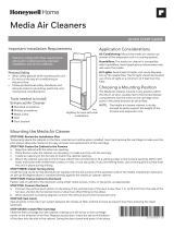
Honeywell F25F1075 is a high-efficiency media air cleaner that captures particles as small as 1 micron. It is applicable to all gas, oil, and electric forced warm air furnaces and to compressor cooling up to 3-1/2 tons. The air cleaner can be used with heat pumps only if the filter is changed regularly to prevent excessive pressure drop. It mounts in the return air duct and requires no electrical connections. The media filter is easily replaced by the homeowner.
Honeywell F25F1075 is a high-efficiency media air cleaner that captures particles as small as 1 micron. It is applicable to all gas, oil, and electric forced warm air furnaces and to compressor cooling up to 3-1/2 tons. The air cleaner can be used with heat pumps only if the filter is changed regularly to prevent excessive pressure drop. It mounts in the return air duct and requires no electrical connections. The media filter is easily replaced by the homeowner.


-
 1
1
-
 2
2
-
 3
3
-
 4
4
-
 5
5
-
 6
6
-
 7
7
-
 8
8
Honeywell F25F Owner's manual
- Type
- Owner's manual
Honeywell F25F1075 is a high-efficiency media air cleaner that captures particles as small as 1 micron. It is applicable to all gas, oil, and electric forced warm air furnaces and to compressor cooling up to 3-1/2 tons. The air cleaner can be used with heat pumps only if the filter is changed regularly to prevent excessive pressure drop. It mounts in the return air duct and requires no electrical connections. The media filter is easily replaced by the homeowner.
Ask a question and I''ll find the answer in the document
Finding information in a document is now easier with AI
Related papers
-
Honeywell F35F1024 User manual
-
Honeywell 69-1866-01 User manual
-
Honeywell TrueCLEAN User manual
-
Honeywell HE480A1006 Owner's manual
-
Honeywell F100F Owner's manual
-
Honeywell 16060 Owner's manual
-
Honeywell F150E1034 Owner's manual
-
Honeywell F200 Owner's manual
-
Honeywell F100 User manual
-
Honeywell F27F1027 Owner's manual
Other documents
-
General AC-1 Owner's manual
-
Crown Boiler CLBR68-112 User manual
-
 Electro-Air EANC2025-A Owner's manual
-
General AC-4 Owner's manual
-
General MAC2000 Owner's manual
-
 Thermo Products OD6FA072DV5R User manual
-
Bryant 907 User manual
-
 Thermo Products OL6FA072D48(B/R) User manual
-
 Honeywell Home F200F2025 User guide
-
Crown Boiler CLBR68-112 User manual


