Hampton Bay HBLG1800H Owner's manual

Type
Owner's manual

Hampton Bay HBLG1800H is a powerful air conditioner that offers a range of features for efficient cooling and heating. With its three cooling and heating modes, you can customize your comfort level according to your needs. The unit is equipped with a washable air filter that helps to remove dust and allergens, ensuring a healthier indoor environment. The adjustable air swing feature allows you to direct the airflow in different directions for better cooling distribution. Additionally, the unit has a ventilation mode that brings in fresh air from outside.

Hampton Bay HBLG1800H is a powerful air conditioner that offers a range of features for efficient cooling and heating. With its three cooling and heating modes, you can customize your comfort level according to your needs. The unit is equipped with a washable air filter that helps to remove dust and allergens, ensuring a healthier indoor environment. The adjustable air swing feature allows you to direct the airflow in different directions for better cooling distribution. Additionally, the unit has a ventilation mode that brings in fresh air from outside.

ROOMAIR CONDITIONER
Please read the operating instructions and safety precautions
carefully and thoroughly before instafling and operating your
room air conditioner,
AIRE ACONDICIONADOR
Pot favor Iea tas instrucciones de operacion y las precauciones
de seguridad cuidadosa y totatmente antes de instai,ar y operar
su acondicionador de aire de ventana.
MODEL, MODELO: HBLG1800H
Manufactured by LG E_ectronics
FOR YOUR RECORDS
Write the modet and serial numbers here:
Model #
Seriat #
You can find them on a tabef en the side of each uniL
Dealer's Name
Date Purchased
B Staple your receipt to this page in the event you need it
to prove date of purchase or for warranty issues.
READ TH|S MANUAL
Inside you will find many helpfu! hints on how to use and
maintain your air conditioner proper_y. Just a Iitfle
preventive care on your part can save you a great dea_ of
time and money over the Ne el your air conditioner.
Yeul_ find many answers to common problems in the char
of iroubieshooting tips, If you review our chart of
Troub|eshooting Tips {irsL you may Hot reed to catt fa_"
service at all,
PRECAUTION
, Contact the suthorized service technician for repair
or maintenance of this unit.
, Contact the installerfor installationof this unit.
, The sir conditioner is not intended for use by young
children or invalids without supervistan.
, Young chitdren should be supe_ised to ensure that
they do not play with the air conditioner:
, When the power cord is to be replaced, replacement
work shs_l be performed by authoT'ized personnel
only using only genuine replacement parts.
. Installation work must be performed in accordance
with the National Electric Code by qualified and
authorized personnel only,
Safety Precautions
To prevent injury to the user or other people and proper_y damage, the following instructions
musf be followed.
t _ncorreetoperation due to ignoring instruction will cause harm or damage, The seriousness
isclassified by the folbwing indications.
I _IL'WAR N_ N G This symb°I indlcates the p°ssibility of death or serious injury 1
_OAUT_ON Thissymbol indi,,,atesthepossibility of injury or damageto properties only.j
[] Meanings of symbols used in this manual are as shown below,
Be net to doo
sure
Be sere to foltow the instrectiono
,/
m Installation
No installation may cause fire and electric
shock accident,
, It maycause fire and electric shock,
it may cause explosion or fire. tt may cause failure and electric shock.
ImOperation -
Other_ise, it wi!l cause electric
shock or fire due to heat
generation or electric shock.
It wilt cause etectric shock or
fire due to heat generation.
ON
* Itwill cause etectric shock or
fire.
. Itwill cause electric shock or
fire due to heat generation.
. It willcause eieetric shock or
fire due to heat generation.
oNo grounding may cause
electric shock (See Installation
Manuat).
. Otherwise it may cause fire . It may cause fire and electric It will cause eiectric shock.
and electric shod<accident, shock,
®
_twill cause failure of machine oIt isnot designed to cool the
or electric shock, entire house.
ott may cause explosion, fire
and burn.
CAUT
- Theyaresharpandmay
causeinjury.
. It may cause failure of
appliance or accident,
oif leaving appliance damaged,
there isconcern of damage
due to the falling of product.
It may cause injury.
Sharp
edges
tt may cause electric shock
and damage,
Prevent accidenta_startup and
the possibility of injury.
Sincethefanrotatesathigh
speedduringoperation,itmay
causeinjury.
Thiscouldinjurethepetor
plant.
oitisanairconditioner,nota
precisionrefrigerationsystem,
oOperationwithoutfilterswill
causefailure.
Theappearanceoftheair
conditionermaydeteriorate,
changecolor,ordevefop
surfaceflaws.
Itcontainscontainmentsand
willmakeyousick,/ This could
damage your health.
About the Controls on the Air Conditioner
The controls will look like one of the following_
Controls
WARNING: To reduce the risk of fire, emectric shock, or injury to
_ persona, read the iMPORTANT SAFETY INSTRUCTIONS before
operating this appliance.
CAUTION: When the air conditioner has been performing its cool[ing
operation and is turned off or set to the fan position, wait at least 3
minutes before resetting to the cooling operation again.
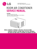
FUNCTION
Thermost_ Operation
A;_toSw_
Hgii H_a Hgl C_'Ol
Wait Ihree t_ir_es
,THERMOSTAT
m the thermostat control _othe desired
setting, The control position is a normal setting
for average conditions. You can change this
setting, i_necessary, in accordance with your
temperature preference.
The thermostat automatically controls cooling or
heating, but the fan runs continuously whenever
the air conditioner is in operation, tf the room is
too warm, turn the thermostat controf clockwise.
If the room is too coot, turn the themostat control
antiolockwise.
Auto Swing
)N : Starts the operationof air swing.
OFF : Stops the operation of air swing.
Please turn off Auto Swing when Operation Switch
iS Off. Auto Swing
Off _ On
=OPERATION
OFF ( O )
FAN (¢)
LOW COOL (8)
HiGH COOL ( _}_)
LOW HEAT (_)
HiGH HEAT ( -?_:r:)
:Turns the ah-conditioner off.
: Permits the tow fan speed
operation without coo_ing
(heating).
: Permits cooii_g with the tow
fan speed operation.
: Permits coofing with the
high tan speed operation.
: Permits heating with the _ow
tan speed operation.
: Permits heating with the
high fan speed operation,
A slight heat odor may come from the unit
when first switching to HEAT aft:er the
cooling season is over. This odor, caused
by fine dust particles on the heater, will
disappear quickly.
Additional controls and important information.
Ventilation
The ventilation lever must be in the CLOSE position in order to maintain the best cooling conditions.
When fresh air is necessary th the room, set:the ventilation leverto the OPEN position.
The damper is opened and room air is drawn out.
CLOS_OPEN
:Before using the ventilation feature,
position the lever, as shown. First, pull down
part ¢: to horizontal line with pa_ ®.
Part
The direction of air can be controlled wherever you want to
cool by adjusting the horizontal louver and the vertical
louver.
°HORIZONTAL AIR-DIRECTION CONTROL
To control horizontal direction of air flow, set to the ON
position the air-swing switch and the air flow wirl be swept
horizontally by the automatic air-swing system.
ff you want to stop the air flow from moving, switch off the
air swing switch at the desired position of the vane.
° VERTICAL AIR-DIRECTION CONTROL
The vertical air direction is adiusted by moving the
horizontal louver.
HowtoAttachDrainPan
The air conditioner employs a proper drain method wherebythe condensedwater (moistureremoved from
the air)is drained to the outside.
Invery hurnidweether,(and for reverse cycle modelsin the reverse mo_) excessivecondensatewater
removed fromthe air may causesome waterto collect. To removethis excess water youcaninstall the
drain pan asdetailed below.
1. Takethe drain pan which is tocatedin the air discharge. CABINET k
2. Removethe hole rubber from the base-pan(forsome models).
3. Instatlthe drain pan to the right cornerof thecabinet with 4 (or 2) - ,
.... _ 2 X
screws.
4. Connectthe drain hose of_/_"insidediameterto the outlet located \\
at thebottom ofthe drain pan.You can purchasethe drain hoseor
tubinglocally to sa_sfyyour particular needs. {Drainhoseis no1
supplied).
ditionerunit.
Selectadrainmethodaccordingtothefollowing.
t. Removetheholerubberfromthebase-pan.(forsomemodels)
2.Connectadrainhoseof_/,#'insidediametertothedrainpipe
asshowninFig.1,
3.Orconnectapipeelbowof%Cinsidediametertothedrain
pipe,thenconnectadrainhoseof_/,¢insidediametertothe
pipeelbowasshowninFig.2.
DRAINPIPE
HOSE
Fig. 1
Care and Maintenance 0 A, , OSE
TURN THE AiR CONDITIONER OFF AND REMOVE THE PLUG FROM THE POWER OUTLET,
AirFilterCleaning
The air filter should be checked at least twice a month to see if cleaning is necessary.
Trapped particles in the fi_ter wifl build up and block the airflow. This reduces the cooling
capacity and also causes an accumulation of frost on the cooling coils.
1. Open the inlet grille upward by pulling out the bottom of the inlet gri_te.(a)
tn another case, you can open the inlet grilte downward by pulling out the top of the inlet
gdHe.(b)
2. Remove the air fi_ter from the fi'ont grille assembty by pL_llingthe air filter up or down
slightly.
3. Wash the filter using _ukewarm water below 40°C (104 °F).(c)
4 Gently shake the excess water from the filter completely. Replace the filter,
(a) (b)
: Mark A of inlet griIIe means opening direction.
(c)
Howto Attach Front Grille to Cabinet
!. Pull down front grille from the cabinet
top.
2. Push front gdlWs tips toward the cabinet
in order to insert front grilte's tabs into
the cabinet
3. Open the inlet grille
4. Tighten the screw through the front grilie
into the pla[e of the evaporator.
5. Close inlet grille.
Features and Installation
Learning parts name prior to installation will help you understand the installation procedure.
Features
<::2
1. CABINET
2 iORIZONTAL AIR DEFLECTOR
(VERTICAL LOUVER)
3, VERTICAL AIR DEFLECTOR
(HORIZONTAL LOUVER)
4. AIR DISCHARGE
5. FRONT GRILLE
6, iNLET GRILLE (AfR _NTAKE)
7. AIR FILTER
8. CONTROL BOARD
9. POWER CORD
1Q. EVAPORATOR
t 1. CONDENSER
!2. COMPRESSOR
13, BASE PAN
14, BRACE
t5. COVER CONTROL
16, ELECTRIC HEATER
INSTALLATION
,
2,
.
.
5_
6,
7.
9.
INSIDE
OUTSIDE FENCE
AWNING
FOAM .....
ED_. HEAT
1/4Bubble RADIATION
-"_.... "- COOL
AIR _ j
About t/Z'
To avoid vibration and noise, make sure the unit isinstalled securely and firmly.
Install the unit where the sunlight does not shine directly on the unit
If the unit _oeives direct sunlight, build an awning to shade the cabinet.
There shou{d be no obstacle, like a fence, within 20" which might restrict heat radiation from the
condenser.
To prevent reducing performance, install the unit so that louvers of the cabinet are not blocked.
tnstalt the unit a little obliquely outward not to avoid leaking the condensed water into the _oom
(about 1/'2"or 114bubble with level).
Install the unit with its bottom portion 30-60" above the floor level
Stuff the foam between the top of the unit and the wall to prevent air and insects flom getting into
the room.
The power cord must be connected to an independent circuft. The green wire must be grounded.
Connect the drain tube to the base pan hole in the rear side if you need to drain (consult a dealer.)
Plastic hose or equivalent may be connected to the drain tube.
How to Use theReversible Inlet Grille
The gritie is designed to clean the fiRer both upward and downward.
(a)
®
"ib)
A. Before attaching the freat grille to the cabinet, ff you want to pull out the
filter upward;
1.Opentheinletgrilfeslightly(a).
2. Turninsideoutthefrontgrille (a).
3.Disassemblethe inlet grille from the front grillewith separatingthe hinged part by inserting a
straighttypescrew-drivertip (b).
4.Then,rotatetheinletgrille180degreesandinsertthehooksintobottomholesofthefrontgrille.
5.Insertthefilterand attachthefront grilleto thecabinet.
B. If you want to pull out the filter downward;
Thegritleisalreadydesignedthatway,
WindowRequirements
NOTE: All supporting parts should be secured to firm wood, masonry, or metal
WINDOW REQUIREMENTS
1, This unit is designed for InstalIation in
standard double hung wi_ldows with actua!
opening widths from 29" to 41".
The top and bottom window sashes must
ope_ sufficiently to alfow a c_ear ve_tica_
opening of 18" from the bottom of the upper
sash to the window stool,
2. The stool offset (height between the stool
and sill) must be less than I /4".
18" rain Stou]- o
Inteno
L 26 !/4" min.
_- Offset
:Z::-MLee
"_"X.! than 1 /4"
.- _E×tefio7
Installation Kits Contents
Foam stdp Foam-PE
(Plain-Back) Adhesive-Backed)
{'Adhesive*Backed)
Lefl frame
curtain
Frameguide(2}
Drainjointpipe
@
bracket
all bracket(2)
p--.._ Support bracket(2)
cuTlai#
TypeA (4) TypeB(7)
Suggested ToolRequirements
SCREWDRIVER(+, RULER, KNIFE, HANMER, PENCIL, LEVEL
PREPARATION OF CHASSIS
!. Remove the screws which fasten the cabinet at
both sides and at the back.
2. Slide the unit out from the cabinet by gdpping the
base par_ handle and pulling forward while
bracing the cabinet.
3. Cut the window sash seal to the proper length. Peel
off the backfng and attach the Foam-PE to the
underside of the window sash.
4. Remove the backit_g from Foam-PE with 3 holes
and attach it to the bottom of the Top retainer bar.
5. Attach the Top retainer bar on the top of the cabinet
v, fi_3 screws (Type A).
6. Insert the Frame guides into the bottom of the
cabinet.
: ,-. the Frame Curtain into the Top retainer bar
and Frame guides.
8. Fasten the curtains to the unit with 10 screws
(Type A} at both sides.
i.
%
. Topretainerbar
Top retainer bar
Screw
CabinetInstallation
1, Open the window. Mark a tine on the center
of the window stool between the side
window stop moldings.
Loosely attach the sill bracket to the support
bracket using the carriage bolt and the lock
nut.
2, Attach the sill bracket to the window sill
using the screws (Type B),
Carefully place the cabinet on the window
stool and align the center mark on the
bottom front with the cente!' line marked
window stool.
,
Using the M-screw and the lock nut, attach
the support bracket to the cabinet track hole.
Use the first track hole after the sill bracket
on the outer edge of the window sill, Tighten
the can-iage bolt and the lock nut. Be sure
the cabinet slants outward,
_k CAUTION: Do net dril_a hole in the
bottom pan, The unit is designed to
operate with approximately 1/2" of water in
bottom pan.
4 Pull the bottom window sash down behind
the Top retainer bar until they meet,
: 1. Do not putl the window sash
down so tightly tllat the
movement of Frame curtain is
restricted. Attach the cabinet to
the window stool by driving the
screws (Type B) through the
cabinet into window stool
Z The cabinet should be installed
with a very slight tilt downward
toward the outside,
Sill
Bracket
(M-Screw)
nut
Fig, 5
:_: Sheoc£nu
Coh,net----.tN S#i
Track hole ' -'_
/ Outer edge
t q"<_/1t J / / of window
Sup sill
Braoket
Carriage bol_-_ "_'x'X _..._'Serew(Type Bt
and lock nut Si_Ibracket
Fig. 6
retainer
bar
Wndowstool
Frontange Fig. 7
Windowsash retainerbar
Foam-PE
Frame curtain
Foam-PE
FrontAngle
Screw(TypeB) Fig. 9
5. Pull each Frame curtain fuliy to each window
sash track, and pul_the bottom window sash
down behind the Top retainer bar until it
meets,
6. Attach each Frarne curtain the window sash
by using screws (Type C.) (See Fig. 10)
7. Stide the unit into the cabinet.(See Fig. 11)
_ CAU:T_ON: For seewlty purpose, reinstall
screws(Type A) at cabinet's sides,
8, Cut the Foam-strip to the proper _ength and
insert between the upper window sash and
the Iower window sash,(See Fig, 12}
9 Attach the Window lock}rig bracket with a
z_!_.-', d,,: C.) (See Fig. 13}
Power Cord
Screw )
Fig, 11
Fig. 12
J
Fig, 13
i 0. Att:,ch tle front gdl_e to the cabinet by
inserting tile tabs on the g_itle into the tabs
on the front of the cabinet. Push the gritle in
untit it snaps into place.(See Fig.14}
11. Lift the inlet grille and secure it with a screw
(T,,_r)eA) through the front grille.(See Fig. I4)
12. Window installation of room air conditioner is
no_, completed. See ELECTRICAL DATA lor
attaching power cord to electrical outlet,
,Fig. 15
ElectricalData
LineCord Plug
circumstances cut
bj
"_ Power cord withsupply
! I 3-prong grounding plug
Use Wall Receptacle
©
Power Supply
k
I Use 20 AMP, time
i delay fuse or circuit
I breaker.
Standard 250V, 3-wire grounding I
receptacle rated 20A, 250V AC
:Aluminum house wiring may pose special problems, Consult a qualified electrician,
I ELECTR;CAL SAFETY
IMPORTANT GROUNDING
INSTRUCTIONS
Air conditioner has a three-prong grounding plug
on its power supply cord, which must be plugged
into propedy grounded three-prong wall
_:_eptaclefor your protection against possible
shock hazard,
FUSE - Use a time-delay fuse or circuit breaker.
Refer to serial plate for proper power supply
requirements.
230, 208, and 230/208 VOLT UNITS
These units are equipped with a threeoprong
grounding plug on the power supply cord, which
must be plugged into a matching properly
grounded three-prong wall receptacle for your
protection against possible shock hazard. If such
an outlet is not present one must be installed by
a qualified electrician in accordance with the
National Electrica_Code and tocal codes and
ordinances.
: DO NOT USEAN EXTENSION
CORD ON 230 208°AND 230/208
VOLT UNITS.
Before you for service...
Troubleshooting Tips
Save time and moneyf Review the chart below first and
you may not need to call for service.
Normal Operating
You may hear a pinging noise caused by water being picked up and thrown against the condenser
on rainy days or when the humidity _shigh, This design feature helps remove moisture and improve
efficiency,
, You may hear the thermostat click when the compressor cycles on and off
° Water wilI collect in the base pan during high humidity or on rainy days. The water may overflow
and drip from the outdoor side of the unit.
oThe fan may run even when the compressor does not,
Air conditioner
does not start
Air conditioner
freezing up
, Make sure the air conditioner plug is pushed
comp!etety into the outbt,
Check the house fuse!circuit breaker box and
replace the fuse or reset the breaker.
, if power failure occurs, turn the mode control to OFF.
When powe__is restored, wait 3 minutes to restart the
air conditioner to prevent tripping of the compressor
overload.
oMake sure there are no curtains, blind& or furniture
blocking the front of the air conditioner,
Turn the knob to a higher number. The highest
setting provides maximum cooling,
. Clean the filter at least every 2 weeks.
See the operating inst[uctions section
When the air conditioner is first turned on
Check for open furnace floor registers
and co_d air returns,
° Set the air condftioneCsvent to the closed position.
See Air Conditioner Freezing Up below,
Set the mode control at High Fan or High Cooi with
thermostat at 1 or 2
  • Page 1 1
  • Page 2 2
  • Page 3 3
  • Page 4 4
  • Page 5 5
  • Page 6 6
  • Page 7 7
  • Page 8 8
  • Page 9 9
  • Page 10 10
  • Page 11 11
  • Page 12 12
  • Page 13 13
  • Page 14 14
  • Page 15 15
  • Page 16 16
  • Page 17 17

Hampton Bay HBLG1800H Owner's manual

Type
Owner's manual

Hampton Bay HBLG1800H is a powerful air conditioner that offers a range of features for efficient cooling and heating. With its three cooling and heating modes, you can customize your comfort level according to your needs. The unit is equipped with a washable air filter that helps to remove dust and allergens, ensuring a healthier indoor environment. The adjustable air swing feature allows you to direct the airflow in different directions for better cooling distribution. Additionally, the unit has a ventilation mode that brings in fresh air from outside.

Ask a question and I''ll find the answer in the document

Finding information in a document is now easier with AI