Westinghouse MB6(B,E,V)M Installation guide
- Type
- Installation guide

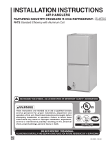
Installation Instructions
Modular Indoor Blower
These instructions are primarily intended to assist qualifi ed individuals experienced in the proper
installation of heating and/or air conditioning appliances. Some local codes require licensed instal-
lation/service personnel for this type equipment. All installations must be in accordance with these
instructions and with all applicable national and local codes and standards.
Before beginning the installation, read these instructions thoroughly and follow all warnings and
cautions in the instructions and on the unit. When performing brazing operations have a fi re extin-
guisher readily available and use a quenching cloth and brazing shield.
Improper installation, service, adjustment, or maintenance can cause fi re, electrical shock or other
conditions which may result in personal injury or property damage. Unless otherwise noted in
these instructions, only factory authorized kits or accessories may be used when modifying this
product.

2
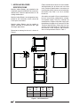
Figure 1. Unit Dimensions
1. MODULAR BLOWER
SPECIFICATIONS
Modular Indoor Blowers are intended to be
mated with specifi c NORDYNE C6 cased coils;
reference the Technical Specifi cations for coil
mating combinations.
Modular Indoor Blowers are designed and ap-
proved for attic, basement, alcove, closet and
crawl space installations.
Modular Indoor Blowers may be applied in
upfl ow, downfl ow or horizontal-left and -right
discharge applications.
Dimensional drawing for the unit is shown in
Figure 1.
Field-installed electric heater kits are available.
Available heater kits for these units are listed
in the Technical Specifi cations. Instructions for
installing the electric heaters are included with
the heaters. See Table 1 for list of available
heater kits.
Air handlers set up with 15 kw or more of electric
heat will normally be confi gured for multiple-
circuit power supply. They may, however, be
connected to a single-circuit power supply with
the addition of a single circuit accessory kit (See
Technical Specifi cations). Select the wire size
and over-current protection in accordance with
the minimum circuit ampacity and maximum
over-current protection shown in Table 1.
"B"
.75
.75
"A"
12.89
.75
1.73
2.87
1.25
Ø 1.125 K.O.
Ø 1.875 K.O.
3.20
1.25
"C"
22.00
1.06
1.87
Ø .875 K.O.
1.88
3.57
5.57
2.62
Ø 1.125 K.O.
Ø 1.750 K.O.
Cabinet
Size
DIM
“A”
DIM
“B”
DIM
“C”
A 12.75 24.75 14.25
B 12.75 24.75 17.50
C 18.25 27.45 21.00

3
Table 1. Minimum Ampacity and Maximum Overcurrent Protection
2. INSTALLATION REQUIREMENTS
Check Equipment — All installations shall
be made as described in these installation
instructions and in accordance with all ap-
plicable national and local codes including the
requirements of local utilities.
Requirements and Codes — Electrical power
wiring must be made in accordance with all ap-
plicable local codes and ordinances, and with
the current revision of the National Electric Code
(ANSI/NFPA 70). Air ducts must be installed in
accordance with the standards of the National
Fire Protection Association “Standard for In-
stallation of Air Conditioning and Ventilation
Systems” (NFPA 90A), “Standard for Installa-
tion of Residence Type Warm Air Heating and
Air Conditioning Systems” (NFPA 90B), these
instructions, and all applicable local codes.
National Fire Protection Association, Inc.
Batterymarch Park
Quincy, Maine 02269
www.nfpa.org
(617) 770-3000
Location — To insure proper condensate drain-
age, the unit must be installed in a level position
within 1/4 inch over the height, width, and depth
of the unit. The best system performance will be
obtained if the unit is located in a centralized po-
sition with respect to the air distribution system.
Refer to Cased Coil Installation Instructions for
proper condensate drain connections.
When an air handler is installed in or above a
living space, the installation of an auxiliary drain
pan under the entire unit is required to reduce
the possibility of property damage. Additionally,
it is recommended that an approved water level
indicator or fl oat switch device be used to shut
down the unit in the event water is detected in
the auxiliary drain pan.
All servicing and cleaning of the air handler can
be done from the front. Adequate horizontal
clearances should be provided to allow for
service and care of the unit. A minimum 24
inch clearance at the front of the unit is rec-
ommended. These units are suitable for attic,
closet, crawl space or alcove installation at zero
clearance from combustibles.
240 VAC, 50 & 60Hz Single Phase 208 VAC, 60Hz Single Phase
Aux. Heat Installed
(Nom. KW)
NONE 005H 008H 010H 015H 020H NONE 005H 008H 010H 015H 020H
Single Circuit
***Min. Circuit Amp.
7.5 32.5 46.6 57.5 82.5 107.5 7.5 29.1 41.2 50.8 72.4 94.0
*Wire AWG 75
o
C
14 8 8(6**) 6 4(3**) 2 14 10(8**) 8 6 4 3
Maximum
Over-current
Rating
15 40 50 60 90 125 15 30 50 60 80 100
Multiple Circuit
Circuit A
***Min. Circuit Amp.
7.5 32.5 46.6 57.5 57.5 57.5 7.5 29.1 41.2 50.8 50.8 50.8
*Wire AWG 60
o
C
14 8 6 4 4 4 14 10(8**) 6 6 6 6
*Wire AWG 75
o
C
14 8 8(6**) 6 6 6 14 10(8**) 8 6 6 6
Maximum
Over-current
Rating
15 40 50 60 60 60 15 30 50 60 60 60
Circuit B
***Min. Circuit Amp.
- - - - 25.0 50.0 - - - - 21.6 43.3
*Wire AWG 60
o
C
----106 - - --106
*Wire AWG 75
o
C
----108 - - --108
Maximum
Over-current
Rating
- - - - 30 60 - - - - 25 50
Circuit C
***Min. Circuit Amp.
------ - - ----
*Wire AWG 60
o
C
------ - - ----
*Wire AWG 75
o
C
------ - - ----
Maximum
Over-current
Rating
------ - - ----
*All wire sizes for copper conductors only, based on NEC Table 310-16.
**Required for C-cabinet variable speed.
***Circuit ampacity slightly higher for variable speed. See label on blower.

4
MATING/JOINING THE UNITS
Modular Indoor Blowers are intended to be
mated with specifi c NORDYNE cased coils;
reference the Technical Specifi cations for coil
mating combinations.
For shipping purposes, the rear bracket and
Downfl ow-Joining bracket are located in the
unit’s heater box. Remove these two parts from
the heater box before beginning.
The following instructions outline the procedure
to join the modular unit with a cased coil in
upfl ow, downfl ow, and horizontal left and right
confi gurations.
Upfl ow Mating — Before mating the modular
unit with the cased coil, remove the screws in
the bracket above the door located on the coil
case. Wipe clean the mating fl anges on both units
surfaces and apply the black neoprene gasket
tape to the top of the coil case fl anges except
for the rear fl ange; making sure to not leave any
gaps on the front and side fl anges.
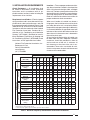
Carefully place the modular blower cabinet on
top of the coil case making sure not to damage
the coil case fl anges. The units will be fl ush in
front with an overhang in the back as shown
in Figure 2.
Remove the lower front bracket from the modular
unit. Attach the front joining bracket to the front
of the modular unit using the screw holes that
were for the lower front bracket, and to the coil
case using the screw holes that were for the
top panel as shown in Figure 3.
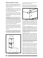
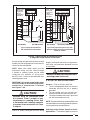
Obtain the Rear Joining Bracket which was
previously removed from the outlet heater box.
Position the bracket fl ush to the sides and back
of the units with the 1/2” insulation facing the
rear gap between the units (see Figure 4.) and
fasten the bracket to the bottom fl anges with
the provided screws. Next, fasten the bracket
to the coil case with the provided self-tapping
screws.
Horizontal Left and Right Mating — reference
the upfl ow mating directions from the previous
paragraphs. Make sure to account for the coil
orientation by confi guring the coil drain pan
assembly properly. You may also reference the
multi-position procedures from the cased coil
Installation Instructions.
Downfl ow mating — Before mating the modular
indoor blower with the cased coil, remove the
lower front bracket located on the modular air
handler making sure to save the screws. Flip
the modular unit upside down, wipe clean the
mating fl anges on both unit surfaces and apply
the black neoprene gasket tape to the modular
units bottom side fl anges which are now facing
upward since the unit was fl ipped; making sure
to not leave any gaps on the sides.
Carefully place the coil case on top of the
modular air handler making sure that the units
are fl ush in the front and on the sides with a
“step” fi t up in the back as shown in Figure 5.
Obtain the front-joining bracket which was
previously removed from the outlet heater box.
Remove the lower cased coil door, remove the
screws on the side of the coil case holding the
lower tie bar, keeping the tie bar in place. Attach
the front joining bracket to the cased coil and
lower tie bar using the screw holes where the
lower tie bar was attached. Attach the front
Figure 2. Upfl ow Installation
Figure 3. Upfl ow Mating

5
joining bracket to the front of the modular unit
where the lower front bracket was removed.
Replace the cased coil door.
Obtain the Rear Joining Bracket which was
previously removed from the outlet heater box.
Position the bracket fl ush to the sides and back
of the units with the 1/2” insulation facing the
rear gap between the units (see Figure 4.) and
fasten the bracket to the bottom fl anges with
the provided screws. Next, fasten the bracket
to the coil case with the provided self-tapping
screws.
that the fi lter be located in the return air duct
system. Installing the fi lter and replacing it
every three months will increase air quality
throughout the home.
WARNING:
Never operate the unit without a fi l-
ter or with the doors removed. Dust
and lint in the return air can build up
on internal components, resulting
in a loss of effi ciency, equipment
damage, and possible fi re risk.
Upfl ow Applications — All Modular Indoor
Blowers are factory shipped ready for upfl ow
confi guration; all return air must enter from the
bottom of the unit. A typical installation of the
unit in a ducted return air mode is shown back
on Figure 2.
Downfl ow Applications — All Modular Indoor
Blowers are factory shipped ready for downfl ow
confi guration; all return air in downfl ow appli-
cations must enter through the top of the unit.
A typical installation of the unit in a downfl ow
application is shown in Figure 5.
Horizontal Left And Horizontal Right —
Modular Indoor Blowers are shipped from the
factory ready for horizontal left applications and
horizontal right applications.
In many applications when joined with a C6
cased coil the shorter horizontal drain pan
Figure 5. Downfl ow Installation
3. AIR DUCTS, FILTERS,
HORIZONTAL APPLICATIONS
Air ducts should be installed in accordance with
the standards of the National Fire Protection
Association “Standard for Installation of Air
Conditioning and Ventilation Systems” (NFPA
90A), “Standard for Installation of Residence
Type Warm Air Heating and Air Conditioning
Systems” (NFPA 90B), these instructions, and
all applicable local codes.
Use transition fi ttings if the supply and/or return
air openings of the unit do not match the duct
openings. These transitions should be dimen-
sioned in accordance with standard practice as
specifi ed in the ASHRAE recommendations for
duct transitions.
Flexible connectors should be used between the
unit and the ductwork to prevent transmission of
vibration from the unit to the structure. If electric
heater kits are installed, heat resistant material
must be used for the fl exible connector at the
supply air end of the unit.
Air Filter Installation — Modular Indoor
Blowers are not equipped with fi lter racking;
however NORDYNE strongly recommends
Figure 4. Rear Joining Bracket

6
extension which is included with the MB6,
must be used. This is to avoid any interference
with the extension included with the C6 and
the blower.
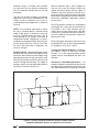
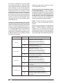
The unit may also be installed in a horizontal
application with the unit suspended from the
ceiling. A typical installation of the unit in a
suspended horizontal application is shown on
Figure 6.
NOTE: In all horizontal applications in which
the unit is installed above a fi nished ceiling
and/or living space, a secondary drain pan
must be installed under the entire unit to
avoid damage to the ceiling in the event of
condensate overfl ow. Additionally, it is recom-
mended that an approved water level indicator
or fl oat switch device be used to shut down
the unit in the event water is detected in the
auxiliary drain pan.
Supply Air Ducts — Bend up the fl anges on the
top of the unit and connect the supply air duct
over them. Secure the duct to the fl ange, using
appropriate fasteners for the type of duct used.
Seal the joint between the duct and the unit to
avoid air leakage and sweating. The supply air
ductwork must be of noncombustible material
for the fi rst 24 inches from the unit.
Some installations with a short, straight run
from the unit to the fi rst branch takeoff may
require acoustical lining inside the supply air
ductwork. Acoustical insulation must be in ac-
cordance with the current revision of the Sheet
Metal and Air Conditioning Contractors National
Association (SMACNA) application standard
for duct liners.
Duct lining material must be UL classifi ed batts
or blankets with a fi re hazard classifi cation of
FHC-25/50 or less. Fiber ductwork may be
used in place of internal duct liners if the fi ber
ductwork is in accordance with the current revi-
sion of the SMACNA construction standard on
fi brous glass ducts.
Fibrous ductwork and internal acoustical lining
must be NFPA Class I air ducts when tested per
UL Standard 181 for Class 1 ducts.
Through-the-Floor Installations — Whenever
the supply or return air ducts pass through
the fl oor, a 1/4” thick noncombustible resilient
gasket must be used between the duct, unit
and fl oor.
Ductwork in Unconditioned Spaces — All
ductwork located in unconditioned space must
be adequately insulated to prevent excess duct
loss and condensation. All externally insulated
Figure 6. Typical Horizontal Installation Using Threaded Rod and
Supporting Members (Shown in Horizontal Left Position)
Threaded Rod
Support Member

7
ductwork must have an adequate vapor seal.
Consult your Distributor for the recommended
type and thickness of insulation for your area
as required by local codes.
WARNING:
To avoid the risk of electric shock,
personal injury or death, disconnect
all electrical power to the unit before
performing any maintenance or ser-
vice. The unit may have more than
one electrical power supply.
4. ELECTRICAL WIRING
General — Electrical power wiring must be
made in accordance with all applicable local
codes and ordinances, and with the current revi-
sion of the National Electric Code (ANSI/NFPA
70). If any of the original wire as supplied with
the unit must be replaced, it must be replaced
with wire material having the same gauge and
temperature rating.
Line Voltage — Before proceeding with the
electrical connections, make certain that the
voltage, frequency, and phase of the supply
source are the same as those specifi ed on the
rating plate. Also, verify that the service provided
by the utility is suffi cient to handle the additional
load imposed by this equipment.
See the unit wiring label for proper high and low
voltage wiring. Make all electrical connections in
accordance with the National Electric Code and
any applicable local codes or ordinances.
Use a separate branch electrical circuit for this
unit. A disconnecting means must be located
within sight of, and readily accessible to, the
unit. When electric heat packages with circuit
breakers are fi eld-installed, the circuit breaker
may be used as a disconnecting means in most
applications. Reference the NEC and Local
Codes for Disconnect requirements.
208/240 volt units are shipped from the fac-
tory wired for 240 volt transformer operation.
For 208 volt operation, remove the lead from
the transformer terminal marked 240v and
connect it to the terminal marked 208v. For
maximum ampacity and overcurrent protection,
see Table 1.
Provide power supply (or supplies) for the unit in
accordance with Table 1, the unit wiring diagram
and the unit rating plate.
When an H6HK heater kit is installed: Connect
the 2 wire plug of the air handler with the mating
2 wire plug of the heater kit. Connect the line
voltage leads to the circuit breaker or terminal
block provided. Connect the heater kit plug
with the mating receptacle on the air handler
control board.
When a heater kit is not installed: Remove the 2
wire plug of the air handler by cutting the wires
and discarding the plug. Strip the ends of the 2
air handler wires and connect to the line-voltage
leads with the 2 wire nuts provided.
Use copper wire only for the line voltage power
supply to this unit. Aluminum supply wire may
be used if a heater kit is installed. Use UL listed
conduit and a conduit connector for connecting
the supply wires to the unit and for obtaining
proper grounding. Grounding may also be ac-
complished by using the grounding lug provided
in the control box.
HEATING ELEMENT LOGIC
The control board in the air handler controls the
timing sequence of the elements. Depending on
the thermostat connection, there are 2 timing
sequence variations that can be chosen. See
table 2 for element sequence timing. The board
also is equipped with a 3 second blower on delay
and a 15 second blower off delay.
WARNING:
The unit cabinet must have an uninter-
rupted and unbroken electrical ground
to minimize the risk of personal injury
if an electrical fault should occur. This
ground may consist of electrical wire
or approved conduit when installed
in accordance with existing national
or local codes.
Low Voltage — Install the grommet, which is
packed with the unit, in the hole for low-voltage
wires. When the low voltage wires are positioned
in this grommet, the grommet will prevent chafi ng
and/or shorting of the low voltage leads. Connect

8
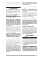
Figure 7. Typical Air Conditioning and Heat Pump System Connections
GRW
2
CEOY
Thermostat
OD
Stat
O Y
R
C
Air Handler Heat Pump OD
Section
GRW
Thermostat
YC
Air Handler A/C OD Section
Y
NOTE: In AC applications, the O and Y connection
must be connected as shown.
GRW
Thermostat
YC
Air Handler A/C OD Section
Y
Typical Air Conditioner w/Standard
Air Handler
GRW
2
CEOY
Thermostat
O Y
R
C
Air Handler Heat Pump OD
Section
Typical Heat Pump w/Standard Air Handler
W
2
NOTE: Jumper
between W2 and E is
required when no OD
T-Stat is used.
W
2
E
Typical Air Conditioner with
Variable Speed Air Handler
Typical Heat Pump with Optional Outdoor
Thermostat and Variable Speed Air Handler
NOTE: Jumper
W1 and W2
together for
shorter
staging time.
See table 2
W2
W1
O
Y/Y2
G
R
C
W2
W1
O
Y/Y2
G
R
C
W2
W1
O
Y/Y2
G
R
C
W2
W1
O
Y/Y2
G
R
C
Y1
Y1
Y1
Y1
NOTE: Jumper
W1 and W2
together for
shorter
staging time.
See table 2
NOTE: Jumper
W1 and W2
together for
shorter
staging time.
See table 2
NOTE: Jumper
W1 and W2
together for
shorter
staging time.
See table 2
* On single stage systems connect to Y/Y2 to obtain selected cooling speed

9
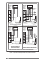
Figure 8. Typical 2-Stage Air Conditioning and
2-Stage Heat Pump System Connections
G R W2 C E O Y1
Thermostat
OD
Stat
O
Y1
R
C
Air Handler
Heat Pump OD
Section
GRW
Thermostat
Y1C
Air Handler A/C OD Section
Y1
NOTE: In AC applications, the O and Y
connection
must be connected as shown.
W
2
E
Typical 2-Stage Air Conditioner
with Variable Speed Air Handler
Typical 2-Stage Cooling Heat Pump with
Optional Outdoor Thermostat and Variable
Speed Air Handler
W2
W1
O
Y/Y2
G
R
C
W2
W1
O
Y/Y2
G
R
C
Y2
Y2
Y2
Y2
W1
W3
R
Y1
Y1
NOTE: Jumper
W1 and W2
together for
shorter
staging time.
See table 2
NOTE: Jumper
W1 and W2
together for
shorter
staging time.
See table 2
the low-voltage wiring to the thermostat and the
outdoor unit and the appropriate screw terminal
located on the control board.
NOTE: Where local codes require that the
thermostat wiring must be routed through
a conduit or raceway, splices can be made
inside the unit; however, all wiring must
be NEC Class 1 and must be separated from
incoming power leads.
IMPORTANT! On variable speed models when
the unit is used in an air conditioning system,
connect the “O” terminal to the “Y” terminal.
See Figures 7 & 8.
CAUTION:
Isolation must be maintained from
the external Class 2 output of any
transformer in a cooling circuit. Use
a thermostat with isolating contacts
to prevent inter-connection of Class
2 outputs.
Check all factory wiring per the unit wiring
diagram and inspect the factory wiring connec-
tions to be sure none were loosened in transit
or installation.
CAUTION:
Make sure all doors are installed before
restoring power to the unit.
5. START-UP AND ADJUSTMENT
General — Prior to start-up, verify that:
1. The line voltage power leads are securely
connected and that the unit is properly
grounded.
2. The low voltage wires are securely con-
nected to the correct leads from the unit.
3. The upper and lower doors are in place and
securely connected to the unit.
NOTE: The control board is programmed with a 40
second off delay in the cooling mode for
optimum
system performance and effi ciency.
Selecting Proper Blower Speed for Multi-
Speed Units — The blower speed is preset at

10
Replace the upper door and secure it to the
unit. Restore power to the unit.
Selecting continuous low speed fan opera-
tion (Standard Blower) — The air handler is
equipped with the option of continuous low speed
fan operation. When G is energized without Y/
Y2, the air handler will operate using the heating
speed. With G & Y/Y2 or Y/Y2 is energized, the
air handler will operate in the selected cooling
speed (including 40 sec blower-off delay).
NOTE: To achieve continuous low speed fan
operation Y must be connected at the air
handler.
Selecting Proper Airfl ow for Variable Speed
Units — Variable speed air handlers are
equipped with a microprocessor-controlled
variable speed motor that is pre-programmed to
deliver optimum airfl ow in a variety of conditions
and system confi gurations. Before operation, the
the factory for operation at the same speed
for heating and cooling, by using the blower
motor jumpering terminal on the blower motor
and connecting it to the desired speed with
both the red and black wires connected to the
jumpering terminal. For optimum system
performance and comfort, it may be necessary
to change the factory set speed. To change the
blower speed, disconnect all electrical power to
the unit and remove the upper door. Remove
the black and red wires from the blower motor
jumpering terminal. Discard the blower motor
jumpering terminal.
Connect the heating speed wire (red) and the
cooling speed wire (black) to the desired blower
speed marked on the terminal block of the blower
motor. On standard 3-speed motors terminal 4 =
Hi speed, terminal 5 = Med. speed and terminal
6 = Low speed. MB6EM units are equipped with
5 selectable blower speeds. Terminal 1=Low
speed, terminal 2=Medium Low speed, terminal
3=Medium speed, terminal 4=Medium Hi speed
and terminal 5=Hi speed
Control Signal Operation Board Action
W1 only
On
Stage 1 Heat on instantly
Heat blower on after 3 second delay
Stage 3 & 5 Heat on after 1 minute delay
Stage 2 Heat on after 2 minute delay
Stage 4 & 6 Heat on after 3 minute delay
Off
Heat stages off instantly
Blower off after 15 second delay
W1 & W2
On
Stage 1 Heat on instantly
Heat blower on after 3 second delay
Stage 3 & 5 Heat on after 10 second delay
Stage 2 Heat on after 20 second delay
Stage 4 & 6 Heat on after 30 second delay
Off
Heat stages off instantly
Blower off after 15 second delay
W1 & Y/Y2
On
Stage 1 Heat on instantly
Cool blower on after 3 second delay
Stage 3 & 5 Heat on after 1 minute delay
Stage 2 Heat on after 2 minute delay
Stage 4 & 6 Heat on after 3 minute delay
Off
Heat stages & Cool blower off instantly
Heat blower energizes and then turns off after 15
second delay
W1, W2 & Y/Y2
On
Stage 1 Heat on instantly
Cool blower on after 3 second delay
Stage 3 & 5 Heat on after 10 second delay
Stage 2 Heat on after 20 second delay
Stage 4 & 6 Heat on after 30 second delay
Off
Heat stages and Cool blower off instantly
Heat blower energizes and then turns off after 15
second delay
Table 2. Heating Element Logic

11
select an airfl ow at or near the top of the
range for that nominal capacity. For maximum
dehumidifi cation, select an airfl ow near the
middle or bottom of the range for that nominal
capacity. Additional information on humidity
control can be found in the sections labeled
“Humidistat” and “Delay Setting”.
NOTE: If coil icing is observed, the basic cooling/
heat-pump airfl ow selected may be too low.
Double-check to be sure the setting selected is
within the range shown in Table 3. Also check
to be sure the system is properly charged (see
outdoor unit Installation Instructions). If icing
continues to occur, raise the selected airfl ow
one or two steps.
When operating in the heat pump mode, a higher
basic airfl ow setting will increase the energy
effi ciency and capacity but will also decrease
the supply air temperature.
Selecting the Minimum Electric Heat
Airfl ow— The minimum electric heat airfl ow is
selected by setting switches 5 and 6. Selecting
the minimum electric heat airfl ow sets the
minimum air fl ow that will be produced whenever
electric heater kits are used. When the electric
heater kits are energized along with a heat pump,
the airfl ow may be higher depending on the basic
cooling/heat-pump airfl ow setting.
Reference Table 4 for recommended minimum
electric heat airfl ow settings. The minimum
electric heat airfl ow setting may be set higher,
but must never be set lower than the setting
shown in Table 4.
Selecting the Delay Profi le— The delay profi le
is selected by setting switches 7 and 8 (see
Table 5). Delay profi le selection controls the
start-up and shut-down characteristics of the air
handler. By varying the start-up and shut-down
characteristics of the air handler the system
can be optimized for energy effi ciency, humidity
control, and comfort.
Select “Delay A” or “Delay B” for highest energy
effi ciency. “Delay A” has a two-step “on” delay.
The blower will begin operation at 31% airfl ow
for 30 seconds. The second step operation is
75% airfl ow for 30 seconds. After the two-step
“on” delay has been completed, the blower
operation will be 100% until the thermostat
has been satisfi ed. “Delay A” also provides a
60 second “off” delay at 50% airfl ow.
“Delay B” has a single step 30 second “on”
delay at 50% airfl ow. “Delay B” also provides
air handler must be confi gured to match the unit
with the system, system options, and climatic
conditions. Once confi gured, the air handler
responds directly to the thermostat inputs, as
well as the optional humidistat (Section 6).
During normal operation, the motor will gradually
change speeds during start-up, shut down,
when thermostat inputs change, and when the
duct static pressure changes (vents closed or
opened, fi lter clogging, etc.). The air handler
is confi gured by setting the selector switches
and removing jumper connectors as directed
below. IMPORTANT! This air handler has
been designed to give the installer maximum
fl exibility to optimize system performance,
effi ciency, and comfort. Because there are
so many different ways to set up the air
handler it is important to read and follow
these directions carefully.
Determining Nominal System Capacity— In
order to select the appropriate airfl ows for the
air handler the nominal system capacity must
be known. The nominal system capacity is
always the nominal capacity of the outdoor unit.
In some cases the nominal system capacity is
not the same as the nominal capacity of the air
handler. Always refer to the nominal capacity
of the outdoor unit to determine the nominal
system capacity.
Selecting the Basic Cooling/Heat Pump
Airfl ow — The basic cooling/heat-pump airfl ow
is selected by setting switches 1 through 4
on the thermostat input board located on the
blower. All airfl ows for other modes of operation
(except electric heat) are determined by this
basic setting.
Table 3 shows the basic airfl ow values versus
the airfl ow selector switch settings. Table 3
also shows the range of basic air fl ow settings
recommended for each nominal system capacity.
“Fan Only” would deliver 50% of the selected
cooling airfl ow.
Note: The 15+ SEER variable speed air handlers
that are matched with a 2-stage cooling outdoor
unit, are programmed to operate at 75% of the
selected airfl ow while the system is in the lo-cool
mode and 100% of the selected airfl ow while
in hi-cool mode.
NOTE: The CFM values listed in the tables are
not dependent on duct static pressure. The motor
automatically compensates for changes in duct
static pressure (within the limits of the motor).
For maximum capacity and energy effi ciency,

12
a 90 second “off” delay at 50% airfl ow. Select
the delay profi le which is most suited to the
application.
The “De-Hum.” delay profi le may be used when
humidity control is desired without the use of
the optional humidistat. If the “De-Hum.” delay
profi le is selected, the air handler will run at 75%
airfl ow for the fi rst 10 minutes of each cooling
cycle. If the “De-Hum.” delay profi le is selected,
the basic cooling/heat-pump speed should be
selected at or near the top of the range for that
nominal capacity (see Table 3).
6. OPTIONAL HUMIDISTAT
(Variable Speed Only)
The optional humidistat may be installed in the
return air duct to provide excellent humidity
control when needed and maximum system
capacity and energy effi ciency when humidity
levels are normal. The humidistat senses when
humidity in the return air stream is above a preset
level (fi eld adjustable) and sends a signal to the
motor to reduce the airfl ow so that more moisture
may be removed until the humidity level drops.
The air handler is pre-programmed for humidistat
operation. Remove jumper connector installed
between the two terminals marked “HUM” on
the circuit board.
Note: The 15+ SEER air handlers that are
matched with a 2-stage cooling outdoor unit
and the humidistat is installed will not drop
below 75% of the selected blower speed when
the system is operating in low-cool mode and
the humidistat opens.
Installation— Install the humidistat in the return
air duct as directed in the installation instructions
included with the kit. Wire the humidistat through
the low-voltage wire entrance in the air handler
(Figure 1) to the quick-connect terminals marked
“HUM”. Wire the humidistat to open on rise in
humidity.
7. CARE AND MAINTENANCE
General — For continued high performance,
and to minimize the risk of equipment failure, it
is essential that periodic maintenance be per-
formed on this equipment. The ability to properly
perform maintenance on this equipment requires
certain mechanical skills and tools. If you do not
possess these skills, contact your dealer for
maintenance. Consult your local dealer as to
the availability of a maintenance contract.
Do not store any of the following on, or in contact
with, the unit: Rags, brooms, vacuum cleaners,
or other cleaning tools, spray or aerosol cans,
soap powders, bleaches, waxes, cleaning
compounds, plastics or plastic containers,
paper bags or other paper products, gasoline,
kerosene, cigarette lighter fl uid, dry cleaning
fl uids, paint thinners, or other volatile fl uids.
Proper maintenance is most important to achieve
the best performance from an air handler. At a
minimum, this maintenance should include the
following items.
1. Inspect and clean or replace the air fi lter at
the beginning of each heating and cooling
season, or more frequently as required.
2. Inspect the cooling coil, drain pan, and
condensate drain at the beginning of each
cooling season for cleanliness. Clean these
components as necessary using a mild
detergent and water. Flush the coil, drain
pan, and condensate drain after cleaning
to remove all detergent. Use caution when
cleaning these components so that the
insulation does not become wet.
3. Inspect the blower motor and wheel for
cleanliness at the beginning of each heat-
ing and cooling season. Clean the motor
as necessary.
4. Inspect electrical connections for tightness
at the beginning of each heating and cooling
season. Service as necessary.
WARNING:
Use caution when removing parts
from this unit. Personal injury can
result from sharp metal edges pres-
ent in all equipment of sheet metal
construction.

13
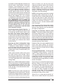
A-CABINET A-CABINET A-CABINET
CFM
Switch
Number
Nominal Capacity
CFM
Switch
Number
Nominal Capacity
CFM
Switch
Number
Nominal Capacity
12341.5 2 2.5 3 12341.5 2 2.5 3
3.5 4
1234 3 3.5 4 5
540 0001 720 0001 1075 0001
600 0000 800 0000 11351001
660 0010 850 1001 1225 0000
715 1001 880 0010 1295 1000
790 1000 945 1000 1380 0010
870 1010 1040 1010 1460 1010
915 0101 1085 0101 1525 0101
955 1101 11401101 1625 1101
1015 0100 1205 0100 1740 0100
1060 0110 1265 1100 1860 1100
1075 1100 1325 0110 1960 0110
11651110 1390 1110 2090 1110
Table 3. Air Flow Selection for Variable Speed Models
A-CABINET
Nominal KW CFM
Switch Number
12345678
0-5 700 0 0
6-9 800 1 0
10-14 950 0 1
15 1100 1 1
B-CABINET
Nominal KW CFM
Switch Number
12345678
0-5 700 0 0
6-10 800 1 0
11-15 950 0 1
16-20 110 1 1
C-CABINET
Nominal KW CFM
Switch Number
12345678
0-9 700 0 0
10-14 950 1 0
15-20 1100 0 1
21-30 1500 1 1
Table 4. Minimum Electric Heat Air Flow
Delay Description
Switch Number
12345678
Delay A 0 0
Delay B 0 1
No Delay 1 0
De-Hum 1 1
Note: 0=Off, 1= On
Table 5. Delay Settings (all models)

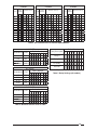
14
MB6BM Blower Performance
Dry Coil ESP 0.10 0.20 0.30 0.40 0.50 0.60 0.70 0.80
0800
A-Cabinet
Low
685 645 605 565 515 465 405 345
Corrected ESP
1
0.07 0.19 0.30 0.42 0.53 0.65 0.76
Med
860 825 780 735 680 625 565 500
Corrected ESP
1
0.11 0.23 0.36 0.48 0.60 0.72
High
1070 1025 975 920 860 800 730 660
Corrected ESP
1
0.14 0.27 0.40 0.53 0.67
Dry Coil ESP
0.10 0.20 0.30 0.40 0.50 0.60 0.70 0.80
1200
A-Cabinet
Low
850 825 795 755 705 645 580 510
Corrected ESP
1
0.04 0.15 0.27 0.38 0.50 0.62 0.74
Med
1120 1085 1045 995 940 875 800 715
Corrected ESP
1
0.04 0.17 0.29 0.42 0.55 0.68
High
1275 1235 1185 1130 1070 1005 935 860
Corrected ESP
1
0.10 0.23 0.36 0.49 0.63
Dry Coil ESP
0.10 0.20 0.30 0.40 0.50 0.60 0.70 0.80
1200
B-Cabinet
Low
995 955 910 845 780 705 610 530
Corrected ESP
1
0.08 0.19 0.31 0.42 0.54 0.65 0.76
Med
1335 1290 1235 1175 1100 1015 925 805
Corrected ESP
1
0.10 0.22 0.34 0.46 0.59 0.71
High
1470 1425 1360 1300 1225 1135 1050 920
Corrected ESP
1
0.08 0.22 0.37 0.51 0.65
Dry Coil ESP
0.10 0.20 0.30 0.40 0.50 0.60 0.70 0.80
1600
C-Cabinet
Low
1035 1005 970 925 875 825 770 710
Corrected ESP
1
0.11 0.22 0.33 0.44 0.54 0.65 0.76
Med
1635 1595 1525 1475 1405 1305 1210 1060
Corrected ESP
1
0.08 0.20 0.32 0.44 0.57 0.69
High
1910 1840 1760 1685 1595 1495 1395 1250
Corrected ESP
1
0.14 0.26 0.39 0.52 0.65
Dry Coil ESP
0.10 0.20 0.30 0.40 0.50 0.60 0.70 0.80
2000
C-Cabinet
Low
1520 1510 1500 1485 1465 1440 1415 1385
Corrected ESP
1
0.11 0.21 0.31 0.42 0.52 0.62 0.72
Med
1900 1885 1860 1830 1790 1740 1680 1620
Corrected ESP
1
0.06 0.16 0.27 0.37 0.48 0.59 0.70
High
2245 2195 2135 2080 2015 1950 1885 1800
Corrected ESP
1
0.12 0.23 0.34 0.45 0.56 0.67
1
ESP estimate with wet coil and fi lter

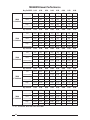
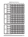
15
MB6EM Blower Performance
Dry Coil ESP 0.10 0.20 0.30 0.40 0.50 0.60 0.70 0.80
1200
A-Cabinet
Tap 1
840 800 760 715 670 625 580 530
Corrected ESP
1
0.08 0.19 0.30 0.42 0.53 0.64 0.75
Tap 2
881 846 810 772 733 693 652 609
Corrected ESP
1
0.07 0.18 0.29 0.40 0.51 0.62 0.73
Tap 3
976 942 907 872 836 799 761 722
Corrected ESP
1
0.03 0.15 0.26 0.37 0.48 0.59 0.70
Tap 4
1250 1224 1194 1159 1119 1074 1025 971
Corrected ESP
1
0.08 0.20 0.33 0.45 0.58
Tap 5
1380 1338 1293 1243 1189 1131 1068 1001
Corrected ESP
1
0.03 0.16 0.30 0.43 0.56
Dry Coil ESP 0.10 0.20 0.30 0.40 0.50 0.60 0.70 0.80
1600
B-Cabinet
Tap 1
1000 858 738 639 562 506 473 460
Corrected ESP
1
0.04 0.18 0.31 0.43 0.54 0.65 0.75
Tap 2
1099 1014 935 864 800 743 693 650
Corrected ESP
1
0.11 0.24 0.36 0.48 0.60 0.71
Tap 3
1318 1277 1234 1187 1139 1087 1033 976
Corrected ESP
1
0.06 0.18 0.30 0.41 0.53 0.65
Tap 4
1502 1466 1428 1388 1345 1299 1251 1201
Corrected ESP
1
0.10 0.21 0.33 0.45 0.57
Tap 5
1624 1592 1557 1520 1480 1438 1393 1346
Corrected ESP
1
0.04 0.15 0.27 0.39 0.51
Dry Coil ESP 0.10 0.20 0.30 0.40 0.50 0.60 0.70 0.80
2000
C-Cabinet
Tap 1
1273 1211 1150 1089 1028 968 907 847
Corrected ESP
1
0.11 0.22 0.33 0.44 0.54 0.65 0.76
Tap 2
1501 1452 1402 1352 1303 1253 1204 1155
Corrected ESP
1
0.07 0.18 0.29 0.40 0.50 0.61 0.72
Tap 3
1697 1654 1610 1564 1517 1469 1420 1370
Corrected ESP
1
0.03 0.14 0.25 0.36 0.47 0.58 0.68
Tap 4
1891 1851 1811 1769 1728 1685 1643 1599
Corrected ESP
1
0.10 0.21 0.32 0.43 0.53 0.64
Tap 5
2096 2056 2015 1974 1932 1890 1847 1803
Corrected ESP
1
0.05 0.16 0.27 0.38 0.49 0.60
1
ESP estimate with wet coil and fi lter

708891B (Replaces 708891A)
Specifi cations and illustrations subject to change
without notice and without incurring obligations.
Printed in U.S.A. (08/09)
¢708891G¤
INSTALLER: PLEASE LEAVE THESE
INSTALLATION INSTRUCTIONS
WITH THE HOMEOWNER
-
 1
1
-
 2
2
-
 3
3
-
 4
4
-
 5
5
-
 6
6
-
 7
7
-
 8
8
-
 9
9
-
 10
10
-
 11
11
-
 12
12
-
 13
13
-
 14
14
-
 15
15
-
 16
16


Westinghouse MB6(B,E,V)M Installation guide
- Type
- Installation guide
Ask a question and I''ll find the answer in the document
Finding information in a document is now easier with AI
Related papers
-
Gibson MB5(B,V)M Installation guide
-
Broan Indoor Air Handler Variable Speed Conversion Kit Installation guide
-
Broan MB6(B,E,V)M Installation guide
-
Broan MB7VM Installation guide
-
Broan Q4SE Installation guide
-
Broan MB7BM Installation guide
-
-
-
-
Other documents
-
Milbank R1773-XL-TG-KK Specification
-
Intertherm H4HK, 15 Kw 240V,1-Phase Electric Heater Kit - A Series Product information
-
Ingersoll-Rand TEM6A0B24H21S Installer's Manual
-
Johnson Controls S1-ECL30 User manual
-
 Heat Controller WDG024VSB-1A Installation, Operation & Maintenance Manual
-
COMFORT-AIRE WDG048VSC-1A-CY Operating instructions
-
Rheem RH2T6021SEACJA Installation guide
-
 Air Handlers Standard R-410A Refrigerant User manual
-
-

