Westinghouse C7B(A,H)M0 Installation guide
- Type
- Installation guide

C7 Series Split System Uncased Indoor Coils
INSTALLATION INSTRUCTIONS
IMPORTANT
ATTENTION INSTALLERS:
It is your responsibility to know this product better than your customer. This includes being
able to install the product according to strict safety guidelines and instructing the customer on
how to operate and maintain the equipment for the life of the product. Safety should always be
the deciding factor when installing this product and using common sense plays an important
role as well. Pay attention to all safety warnings and any other special notes highlighted in the
manual. Improper installation of the furnace or failure to follow safety warnings could result in
serious injury, death, or property damage.
These instructions are primarily intended to assist qualified individuals experienced in the proper
installation of this appliance. Some local codes require licensed installation/service personnel
for this type of equipment. Please read all instructions carefully before starting the installation.
Return these instructions to the customer’s package for future reference.
DO NOT DESTROY. PLEASE READ CAREFULLY & KEEP IN A SAFE PLACE FOR FUTURE REFERENCE.

2
IMPORTANT SAFETY INFORMATION
Please read all instructions before servicing this equipment.
Pay attention to all safety warnings and any other special
notes highlighted in the manual. Safety markings are
used frequently throughout this manual to designate a
degree or level of seriousness and should not be ignored.
WARNING indicates a potentially hazardous situation that
if not avoided, could result in personal injury or death.
CAUTION indicates a potentially hazardous situation that
if not avoided, may result in minor or moderate injury or
property damage.
WARNING:
This unit must be installed in accordance
with the instructions outlined in this manual
during the installation, service, and operation
of this unit. Unqualified individuals should
not attempt to interpret these instructions or
install this equipment. If you do not posses
mechanical skills or tools, call your local dealer
for assistance. Under no circumstances should
the equipment owner attempt to install and/or
service this equipment. Failure to follow safety
recommendations could result in possible
damage to the equipment, serious personal
injury or death.
• The installer must comply with all local codes and
regulations which govern the installation of this type
of equipment. Local codes and regulations take
precedence over any recommendations contained in
these instructions. Consult local building codes for
special installation requirements.
• Familiarizeyourselfwiththecontrolsthatshutoffthe
electrical power to the unit. If the unit needs to be shut
down for an extended period of time, turn off electrical
power at the circuit breaker. For your safety always
turn off the electrical power before performing service
or maintenance on the unit.
• Installationofequipmentmayrequirebrazingoperations.
Installer must comply with safety codes and wear
appropriate safety equipment (safety glasses, work
gloves, fire extinguisher, etc.) when performing brazing
operations.
• Read the Installation Instructions supplied with the
furnace or air handler. Always observe all safety
requirements outlined in this manual and on the furnace
or air handler markings before installing the coil.
• Follow all precautions in the literature, on tags, and
on labels provided with the equipment. Read and
thoroughly understand the instructions provided with
the equipment prior to performing the installation and
operational checkout of the equipment.
WARNING:
C7 coils are pressurized with Nitrogen at the
factory. Avoid direct face exposure or contact
with valve when gas is escaping. Always ensure
adequate ventilation is present during the
depressurization process. Any uncertainties
should be addressed before proceeding.
NITROGEN
HEALTH
FLAMMABILITY
REACTIVITY
0 Minimal Hazard
1 Slight Hazard
1
0
0
WARNING:
Improper installation, service, adjustment, or
maintenance may cause explosion, fire, electrical
shock or other hazardous conditions which may
result in personal injury or property damage.
Unless otherwise noted in these instructions,
only factory authorized kits or accessories may
be used with this product.
WARNING:
PROPOSITION 65 WARNING: This product
contains chemicals known to the state of
California to cause cancer, birth defects or other
reproductive harm.

3
GENERAL INFORMATION
C7 Series uncased indoor coils are designed for upflow,
downflow, or horizontal applications and are equipped with
braze type refrigerant connections for easy installation.
• IfaTXVisnotinstalledbutrequiredforyourapplication,
seeTable1(page7)todeterminetheproperkitbased
on tonnage and refrigerant type of the unit.
• Checkthecoilsoricesizeandconrmthatit’ssuitable
for application with the intended outdoor unit. Depending
on application, additional installer supplied orifice or
TXVmayberequired.
• Optional cooling/heating equipment must be
properly sized and installed in accordance with the
furnace manufacturer’s specications and approved
recommendations.
• “HeatingOnly”furnaceaircirculatorsmayhavetobe
replacedwithmulti-speedHeating/Coolingblowers
to upgrade the air delivery (CFM) when an add-on
coilisinstalled.RefertoTables2&3(page7)forcoil
specications,recommendedCFM,andallowancesfor
pressure drop across the coil and filters.
• Verifythattheairdeliveryofthefurnace/airhandleris
adequate to handle the static pressure drop of the coil,
filter, and duct work.
• Ifpreciseformingofrefrigerantlinesisrequired,acopper
tubing bender is recommended. Avoid sharp bends and
contact of the refrigerant lines with metal surfaces.
• Refrigerant lines should be wrapped with pressure
sensitive neoprene or other suitable material where
they pass against sharply edged sheet metal.
• Horizontalinstallationsrequireahorizontaldrainpan
kittobeinstalled.SeeTables2&3foravailablepart
numbers.
• Close-off plates are available in some air lter kits.
RefertotheReplacementPartsListforavailablepart
numbers. Install the necessary close-off plates around
the refrigerant lines and drain line where required.
Reinstallallinnerandouterpanelsofthefurnace/air
handler that were previously removed when installing
the indoor coil.
COIL INSTALLATION
WARNING:
ELECTRICAL SHOCK, FIRE OR
EXPLOSION HAZARD
Failure to follow safety warnings exactly could
result in serious injury or property damage.
Improper servicing could result in dangerous
operation, serious injury, death or property
damage.
to the unit.
to disconnecting. Reconnect wires correctly.
CAUTION:
The coil must be level to ensure proper
condensate drainage. An unlevel installation may
result in structural damage, premature equipment
failure, or possible personal injury.
NOTE TO INSTALLER: C7 Coils are not factory charged
with refrigerant. It will be necessary to evacuate the indoor
coiland lineset prior tocharging. Refer tothe outdoor
unit installation manual for detailed charging instructions.
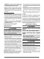
Upflow Installations
1.Disconnectallelectricalpowertothefurnace.
2. Install the coil case on the furnace air discharge opening
and level it as needed to ensure proper condensate
drainage. If needed, make a plate to adapt the coil to
theairdischargeopening.SeeFigure5(page6)for
coil dimensions.
3.Makeandinstalltheplenumoverthecoil.Insulateas
required.
4. Seal the enclosure as required to minimize air leakage.
5.Connect the refrigerant lines as outlined in the
RefrigerantLineConnectionsection.
Downflow Installations
C7 coils may be installed in downflow applications. It is
required that the furnace and coil cabinets are securely
mounted together before setting in place. Fossil fuel
applications require the coil to be placed in the supply
air stream only.
Horizontal Installations
C7 coils can be installed horizontally, but it is required that
the furnace and coil cabinets be securely mounted together
before setting in place. A horizontal drain pan kit must
alsobeinstalledunderthefurnaceorairhandler.Refer
totheReplacementPartsListforavailablepartnumbers.
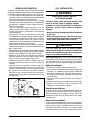
Suction
Line
Liquid
Line
Cap
Schrader
Valve
Figure 1. Suction & Liquid Line Locations

4
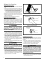
Figure 2.
Install restrictor with
rounded end down
in the distributor
Figure 4.
Figure 3. Removal of Orifice
Carefully remove the
restrictor orifice from
the distributor body
Refrigerant Line Connections
System Depressurization
1.Removethecap(Figure1)fromtheendoftheliquid
line.
2.VerifypressurizationbydepressingtheSchradervalve
on the end of the liquid line. Listen for any escaping gas.
If there is no pressure, test the coil for leakage.
• Ifleakageisfound,clearlymarkthelocationofthe
leak and return the coil to the distributor for processing.
• Ifnoleaksarefound,thecoilmaybeinstalled.
3. Depress the valve to relieve all pressure from the coil.
4.Remove and discard the valve core and valve core
holder on the liquid line.
5.Removetherubberplugfromthesuctionline.
OriceRemoval&Installation
NOTE: Before proceeding, perform steps 1 - 3 in the
System Depressurization section and confirm that the
restrictor orifice size meets the requirements outlined
intheoutdoorunitinstallationmanual.Factorysupplied
oricesizesarelistedinTable2(page7).Iftheorice
mustbereplaced,followsteps1-5.
CAUTION:
To prevent damage to the unit or internal
components, it is recommended that two
wrenches be used when loosening or tightening
nuts. Do not over tighten!
1.Usingtwowrenches,loosenthenutanddistributorbody
asshowninFigure2.Turntheassemblynutcounter-
clock-wise until the orifice body halves are seperated.
2. Insert a light-gauge wire hook between the distributor
body and the restrictor orifice while being careful not
to scratch either part. Carefully remove the restrictor
oricefromthedistributorbody.SeeFigure3.
3.Check the actual sizeof theneworice.The sizeis
stamped on its side. Do not use pin gauges to measure
the orifice diameter.
4. Insert the new orifice into the distributor body, rounded
enddown.SeeFigure4.
CAUTION:
To prevent damage to the unit or internal
components, it is recommended that two
wrenches be used when loosening or tightening
nuts. Do not over tighten!
5.Realigntheassemblynutonthedistributorbodyand
hand tighten both components. Mark a line on both
bodiesandthentightenanadditional1/4turnusingtwo
wrenches.Themovementofthetwolineswillshowhow
much the nut is tightened. If a torque wrench is used,
tightento10-12ft.lbs.or14-16Nm.
Connecting the Linesets
NOTE:IfinstallingaTXV,pleasefollowtheinstructions
suppliedwiththekit.SeeTable1 (page 7) for kit part
numbers.
1.Routeand cut both lineset tubestoproperlengthin
accordancewiththeoutdoorunitspecications.Verify
the ends are round, clean, and free of any burrs.
2. Connect the suction and liquid lineset tubes.
CAUTION:
It is recommended that a wet rag be wrapped
around the suction line in front of the close
off plate before applying heat. Failure to keep
components cool during brazing may result in
structural damage, premature equipment failure,
or possible personal injury.
3. Braze the individual connections with dry nitrogen flowing
throughthejoints.Thiswillpreventinternaloxidation
and scaling from occurring.

5
IMPORTANT: To prevent internal oxidation and
scaling from occuring, braze all connections with
dry nitrogen flowing through the joints.
4. Wrap the refrigerant lines with pressure sensitive
neoprene or other suitable material especially
where the lines enter the opening in the sheet metal.
NOTE:OnhorizontalmodelswithaTXVvalve,reposition
thesensingbulbtothe4or8o’clockpositiononthe
suction line.
Completing the Installation
1.Checkthesystemforleaks,includingthelinesetandthe
brazed joints. NOTE: Apply a soap and water solution on
each joint or union with a small paintbrush. If bubbling
is observed, the connection is not adequately sealed.
2. Evacuate the system of moisture and non-condensables
to prevent low efficiency operation or damage to the
unit.Thesuggestedrangeofevacuationis250-500
microns.
3. Charge the system with refrigerant. Please Refer to
the outdoor unit installation manual for additional
charging instructions.
4. Install the coil access door (if removed).
5.Properlydisposeofallremovedparts.
6.Applypowertotheunit.
Condensate Drain
CAUTION:
The coil must be level to ensure proper condensate
drainage. Improper condensate disposal may
result in structural damage, premature equipment
failure, or possible personal injury.
• Methodsfordisposingofcondensatevaryaccording
tolocalcodes.Refertolocalcodesorauthorityhaving
jurisidiction for restrictions and proper condensate
disposal requirements.
• Allcondensatepanshaveprimaryandsecondarydrain
connectionstomeetFHArequirements.Iftheapplication
is located in or above a living space where damage
mayresultfromcondensateoverow,aseparate3/4
inch drain must be provided from the secondary drain
connection and a secondary drain pan must be installed
undertheentireunit.Runsecondarydrainlinestoa
place where they are noticeable if used.
• Thecoilcondensatepanisdesignedwith3/4”NPSC
drainconnections.UseaPVCorsimilarmaterialtting
to attach the drain line to the pan. NOTE:Thetting
should be hand tightened only. Overtightening may
crack the drain pan and cause condensate to leak.
• The drain pan MUST be drained with eld supplied
tubing and looped to form a trap.
IMPORTANT: Failure to install a trap may result in
condensation overflowing the drain pan, resulting in
substantial water damage to surrounding area.
• Primethetrapwithwater.Insulatethedrainifitislocated
in an unconditioned space, and test the condensate line
for leaks. Consult local codes for additional restrictions
or precautions.
• Routethelinestoasuitabledrain,avoidingsharpbends
andpinchingofthelines.Thedrainshouldmaintaina
minimum horizontal slope in the direction of discharge
ofnolessthan1”verticalforevery10ftofhorizontal
run.
• During system checkout, inspect the drain line and
connections to verify proper condensate drainage.
Air Filter
Air filters are not supplied as an integral part of this
coil; however, an air lter kit is available. Refer to the
ReplacementPartsListforavailablepartnumbers.
The lter must be installed upstream of the coil and
inspected frequently. When the filter becomes clogged
with dust or lint, it should be replaced (disposable type)
or cleaned (washable type). It is recommended that filters
be inspected and replaced at least twice during the year.
Generally it is best to replace or clean the filters at the
start of each heating and cooling season.
WARNING:
ELECTRICAL SHOCK, FIRE OR EXPLOSION
HAZARD
Failure to follow safety warnings exactly could
result in serious injury or property damage.
Improper servicing could result in dangerous
operation, serious injury, death or property
damage.
to the furnace or air handler.
to disconnecting. Reconnect wires correctly.
CAUTION:
Do not operate the system without a suitable filter
in the return air duct system. Always replace the
filter with the same size and type.
Toensureoptimumperformanceandtominimizepossible
equipment failure, the following maintenance tasks should
be performed periodically on this equipment:
1.Theairlterinstalledwiththesystemshouldbechecked
and cleaned or replaced twice per year.
2. Check the coil, drain pan, and condensate drain line
for cleanliness at the start of each heating and cooling
season. Clean as needed.

6
Figure 5.
W
2 1/2
HS
HL
3 1/8
19 1/2
H
3 1/8
2 1/2
19 1/2
HS
HL
H
W
TXV
Figure 6.

7
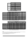
01824A 03036A 030C 03648C 048C 060C 042D 048D 060D
NomiNal CapaCity, miN BtUH 18,000 30,000 18,000 30,000 36,000
30,000
36,000
48,000 60,000 42,000 48,000 60,000
NomiNal CapaCity, max BtUH 24,000 36,000 24,000 36,000 42,000 48,000
iNstalled orifiCe size (iN.) .048 .061 .055 .067 .071 .061 .067 .077 .083 .071 .077 .083
NomiNal airflow, miN (Cfm) 800 1,000 800 1,000 1,200
1,000
1,200
1,600 2,000 1,400 1,600 2,000
NomiNal airflow, max (Cfm) 800 1,000 800 1,200 1,400 1,600
w - widtH (iN.) 123/4 123/4 16 16 16 191/2 191/2 191/2 191/2 23 23 23
H - HeigHt (iN.) 181/2 181/2 18 18 25 18 241/2 281/2 281/2 233/4 273/4 273/4
Hl - HeigHt of liqUid liNe (iN.) 171/2 171/2 171/2 171/2 231/2 231/2 231/2 27 27 27 27 27
Hs - HeigHt of sUCtioN liNe (iN.) 151/2 151/2 151/2 151/2 211/2 211/2 211/2 25 25 25 25 25
CoNNeCtioN - liqUid liNe 3/8 3/8 3/8 3/8 3/8 3/8 3/8 3/8 3/8 3/8 3/8 3/8
CoNNeCtioN - sUCtioN liNe 3/4 3/4 3/4 3/4 7/8 7/8 7/8 7/8 7/8 7/8 7/8 7/8
HorizoNtal draiN paN Kit 920265 920265 920265 920265 920266 920265 920266 920267 920267 920267 920267 920267
Table 1.
R-22
REFRIGERANT
920662A 1.5or2
920663A 2.5
920664A 3
920665A 3.5
920666A 4
920667A 5
R-410A
REFRIGERANT
920668A 1.5or2
920669A 2.5
920670A 3
920671A 3.5
920672A 4
920673A 5
Table 2.
X24C-A X30C-A X36C-A X30C-C X36C-C X42C-C X48C-C X60C-C X48C-D X60C-D
NomiNal CapaCity, BtUH
24,000 30,000 36,000 24,000 30,000 36,000 30,000 36,000 42,000 48,000 60,000 48,000 60,000
meteriNg deviCe TXV TXV TXV TXV TXV TXV TXV TXV TXV TXV TXV TXV TXV
NomiNal airflow, (Cfm) 800 1000 1000 800 1000 1200 1000 1200 1400 1600 2000 1600 2000
w - widtH (iN.) 12.75 12.75 12.75 16 16 16 19.5 19.5 19.5 19.5 19.5 23 23
H - HeigHt (iN.) 18.5 18.5 18.5 18 18 18 18 24.5 24.5 24.5 28.5 27.75 27.75
Hl - HeigHt of liqUid liNe (iN.) 17.5 17.5 17.5 17.5 17.5 17.5 23.5 23.5 23.5 23.5 27 27 27
Hs - HeigHt of sUCtioN liNe (iN.) 15.5 15.5 15.5 15.5 15.5 15.5 21.5 21.5 21.5 21.5 25 25 25
CoNNeCtioN - liqUid liNe 3/8 3/8 3/8 3/8 3/8 3/8 3/8 3/8 3/8 3/8 3/8 3/8 3/8
CoNNeCtioN - sUCtioN liNe 3/4 3/4 3/4 3/4 3/4 3/4 3/4 7/8 7/8 7/8 7/8 7/8 7/8
HorizoNtal draiN paN Kit 920265 920265 920265 920265 920265 920265 920265 920266 920266 920266 920267 920267 920267
Table 3.
NOTES:
1. Individualrestrictorsareavailablebypartnumber-PN664***(where***representsthesize).Example:664103isarestrictor0.103indiameter.
2. RefertosalesspecicationsheetsforListed/Certiedcombinationsofequipmentandrequiredaccessories.
3. XinthemodeldescriptiondesignatesfactoryinstalledTXVforR-410arefrigerant.
4. RefertothecurrentAHRIDirectoryforcertiedratingsofsplitsystems.
5. Notrequiredfor“H”horizontalreadycoils.

INSTALLER:PLEASELEAVETHESEINSTRUCTIONSWITHTHEEQUIPMENTOWNER.
709345D (Replaces709345C)
Specications&illustrationssubjecttochangewithoutnoticeorincurringobligations(05/15).
O’Fallon,MO,©NortekGlobalHVACLLC2015.AllRightsReserved.
-
 1
1
-
 2
2
-
 3
3
-
 4
4
-
 5
5
-
 6
6
-
 7
7
-
 8
8


Westinghouse C7B(A,H)M0 Installation guide
- Type
- Installation guide
Ask a question and I''ll find the answer in the document
Finding information in a document is now easier with AI
Related papers
-
Broan C7B(A,H)MX Installation guide
-
Broan C7B(A,H)M0 Installation guide
-
-
-
Broan C6B(A,H)-F Installation guide
-
-
-
-
Broan JS6BD-K Installation guide
-
Other documents
-
Broan C6DA-T Installation guide
-
Intertherm B6BX Installation guide
-
Broan C(3,5)QA Installation guide
-
-
Broan C8BA Installation guide
-
-
Broan C8DA Installation guide
-
-
Intertherm C3(D,Q)-0 Installation guide
-
 Climate Master TAH038CGSMBS User guide
