
User´s Guide
LXG cameras (Gigabit Ethernet)
Document Version: v2.7
Release: 08.01.21
Document Number: 11129236

2

3
Table of Contents
1. General Information ................................................................................................. 6
2. General safety instructions ..................................................................................... 7
3. Intended Use ............................................................................................................. 7
4. General Description ................................................................................................. 7
5. Camera Models ......................................................................................................... 8
5.1 LXG – Camera ........................................................................................................ 8
5.2 Lens Mount Adapter .............................................................................................. 10
5.3 Flange Focal Distance .......................................................................................... 12
6. Installation .............................................................................................................. 12
6.1 Environmental Requirements ................................................................................ 12
6.2 Heat Transmission ................................................................................................ 13
6.2.1 Emergency shutdown at Overtemperature .................................................... 14
6.3 Mechanical Tests ................................................................................................... 15
7. Process- and Data Interface .................................................................................. 16
7.1 Pin-Assignment Interface ...................................................................................... 16
7.2 Pin-Assignment Power Supply and Digital-IOs ..................................................... 16
7.3 Power saving Mechanisms ................................................................................... 17
7.4 LED Signaling ....................................................................................................... 18
8. ProductSpecications .......................................................................................... 19
8.1 Sensor Specications ........................................................................................... 19
8.1.1 Quantum Eciency for Baumer LXG Cameras .............................................. 19
8.1.2 Shutter ............................................................................................................ 20
8.1.3 Digitization Taps ............................................................................................ 20
8.1.4 Field of View Position ..................................................................................... 21
8.2 Timings .................................................................................................................. 22
8.2.1 Free Running Mode ........................................................................................ 22
8.2.2 Trigger Mode .................................................................................................. 23
9. Software .................................................................................................................. 27
9.1 Baumer GAPI ........................................................................................................ 27
9.2 3
rd
Party Software .................................................................................................. 27
10. Camera Functionalities .......................................................................................... 28
10.1 Image Acquisition ................................................................................................ 28
10.1.1 Live Mode / Buered Mode .......................................................................... 28
10.1.2 Image Format ............................................................................................... 29
10.1.3 Pixel Format ................................................................................................. 30
10.1.4 Exposure Time.............................................................................................. 32
10.1.5 PRNU / DSNU Correction (FPN - Fixed Pattern Noise) ............................... 32
10.1.6 HDR (except LXG-500) ................................................................................ 33

4
10.1.7 Look-Up-Table .............................................................................................. 33
10.1.8 Gamma Correction ....................................................................................... 34
10.1.9 Region of Interest (ROI) and Multi ROI ........................................................ 34
10.1.10 Multi-ROI .................................................................................................... 35
10.1.11 Binning ........................................................................................................ 36
10.1.12 Decimation (sub-sampling) ......................................................................... 37
10.1.13 Brightness Correction (Binning Correction) ................................................ 38
10.2 Color Adjustment – White Balance ..................................................................... 38
10.2.1 User-specic Color Adjustment .................................................................... 38
10.2.2 One Push White Balance ............................................................................. 38
10.3 Analog Controls ................................................................................................... 39
10.3.1 Oset / Black Level ....................................................................................... 39
10.3.2 Gain .............................................................................................................. 39
10.4 Pixel Correction ................................................................................................... 40
10.4.1 General information ...................................................................................... 40
10.4.2 Correction Algorithm ..................................................................................... 40
10.4.3 Add Defect Pixel / Defect Columns / Defect Rows to Defect pixel list .......... 41
10.5 Sequencer ........................................................................................................... 42
10.5.1 General Information ...................................................................................... 42
10.5.2 Baumer Optronic Sequencer in Camera xml-le .......................................... 43
10.5.3 Examples ...................................................................................................... 44
10.5.4 Capability Characteristics of Baumer GAPI Sequencer Module .................. 44
10.5.5 Double Shutter ............................................................................................. 45
10.6 Process Interface ................................................................................................ 46
10.6.1 Digital I/O ...................................................................................................... 46
10.7 Trigger Input / Trigger Delay ............................................................................... 48
10.7.1 Trigger Source .............................................................................................. 49
10.7.2 Debouncer .................................................................................................... 50
10.7.3 Flash Signal .................................................................................................. 50
10.7.4 Timer............................................................................................................. 51
10.8 User Sets ............................................................................................................ 52
10.9 Factory Settings .................................................................................................. 52
11. Interface Functionalities ........................................................................................ 53
11.1 Link Aggregation Group Conguration ................................................................ 53
11.1.1 Camera Control ............................................................................................ 53
11.1.2 Image data stream ........................................................................................ 53
11.2 Device Information .............................................................................................. 54
11.3 Baumer Image Info Header (Chunk Data)........................................................... 55
11.4 Packet Size and Maximum Transmission Unit (MTU) ......................................... 56
11.5 "Inter Packet Gap" (IPG) .................................................................................... 57
11.5.1 Example 1: Multi Camera Operation – Minimal IPG ..................................... 57
11.5.2 Example 2: Multi Camera Operation – Optimal IPG ..................................... 58
11.6 Frame Delay ........................................................................................................ 59
11.6.1 Time Saving in Multi-Camera Operation ....................................................... 59
11.6.2 Conguration Example ................................................................................. 60
11.7 Multicast .............................................................................................................. 62
11.8 IP Conguration ................................................................................................... 63
11.8.1 Persistent IP ................................................................................................. 63
11.8.2 DHCP (Dynamic Host Conguration Protocol) ............................................. 63
11.8.3 LLA ................................................................................................................ 64
11.8.4 Force IP ........................................................................................................ 64
11.9 Packet Resend .................................................................................................... 65
11.9.1 Normal Case ................................................................................................. 65
11.9.2 Fault 1: Lost Packet within Data Stream ....................................................... 65

5
11.9.3 Fault 2: Lost Packet at the End of the Data Stream ..................................... 66
11.9.4 Termination Conditions ................................................................................ 66
11.10 Message Channel ............................................................................................. 67
11.11 Action Commands ............................................................................................. 68
11.11.1 Action Command Trigger ............................................................................ 68
12. Start-Stop-Behaviour ............................................................................................. 69
12.1 Start / Stop Acquisition (Camera) ........................................................................ 69
12.2 Start / Stop Interface ........................................................................................... 69
12.3 Pause / Resume Interface .................................................................................. 69
12.4 Acquisition Modes ............................................................................................... 69
12.4.1 Free Running ................................................................................................ 69
12.4.2 Trigger .......................................................................................................... 69
12.4.3 Sequencer .................................................................................................... 69
13. Cleaning .................................................................................................................. 70
13.1 Sensor ................................................................................................................. 70
13.2 Cover glass ......................................................................................................... 70
13.3 Housing ............................................................................................................... 70
14. Transport / Storage ................................................................................................ 71
15. Disposal .................................................................................................................. 71
16. Warranty Information ............................................................................................. 71
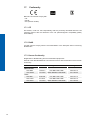
17. Conformity .............................................................................................................. 72
17.1 CE ....................................................................................................................... 72
17.1.1 RoHS ............................................................................................................ 72
17.2 Korean Conformity .............................................................................................. 72
18. Support .................................................................................................................... 73

6
1. General Information
Thanks for purchasing a camera of the Baumer family. This User´s Guide describes how
to connect, set up and use the camera.
Read this manual carefully and observe the notes and safety instructions!
Target group for this User´s Guide
This User's Guide is aimed at experienced users, which want to integrate camera(s) into
a vision system.
Copyright
Any duplication or reprinting of this documentation, in whole or in part, and the reproduc-
tion of the illustrations even in modied form is permitted only with the written approval of
Baumer. This document is subject to change without notice.
Classicationofthesafetyinstructions
In the User´s Guide, the safety instructions are classied as follows:
Notice
Gives helpful notes on operation or other general recommendations.
Caution
Pictogram
Indicates a possibly dangerous situation. If the situation is not avoided,slight
or minor injury could result or the device may be damaged.

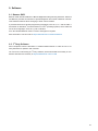
7
2. General safety instructions
Observe the the following safety instruction when using the camera to avoid any damage
or injuries.
Caution
Provide adequate dissipation of heat, to ensure that the temperature does
not exceed +50 °C (+122 °F).
The surface of the camera may be hot during operation and immediately
after use. Be careful when handling the camera and avoid contact over a
longer period.
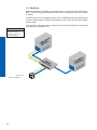
3. Intended Use
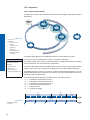
The camera is used to capture images that can be transferred over two GigE interfaces
to a PC.
Notice
Use the camera only for its intended purpose!
For any use that is not described in the technical documentation poses dangers and will
void the warranty. The risk has to be borne solely by the unit´s owner.
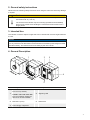
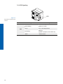
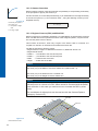
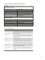
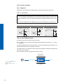
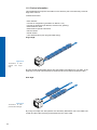
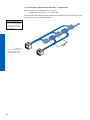
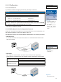
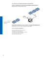
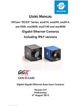
4. General Description
1
2
3
4
5
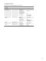
No. Description No. Description
1
LXG-20 / 40
lens mount (C-Mount)
LXG-80 / 120 / 200 / 250 / 500
lens mount (M58), adapter for
other lens mounts available
4 Signaling LED
2 Data Port 1 (PoE) 5 Data Port 2
3 Power Suppy / Digital-IO

8
5. Camera Models
5.1 LXG – Camera
LXG-20M / C / NIR
LXG-40M / C / NIR
LXG-80M / C
LXG-120M / C
LXG-200M / C
LXG-250M / C
LXG-500M / C
Camera Type
Sensor
Size
Resolution
Full Frames
[max. fps]
Monochrome / Color
LXG-20M / C / NIR 2/3" 2048 x 1088 111
LXG-40M / C / NIR 1" 2048 x 2048 59
LXG-80M / C 4/3" 3360 x 2496 29
LXG-120M / C APS-C 4096 x 3072 19
LXG-200M / C 35 mm 5120 x 3840 12
LXG-250M / C APS-H 5120 x 5120 9
LXG-500M / C 35 mm 7920 x 6004 5

9
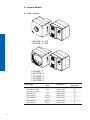
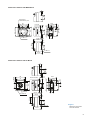
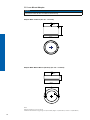
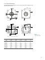
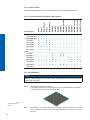
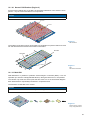
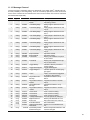
Dimensions Camera with M58-Mount
47
60
47
60
M58 x 0,75
Pixel 0,0
4 x M3 x 6
44,75
52,35
55,45
35,8
8
26
8 x M3 x 6
8
26
12 ±0,25
8
26
14,7
19,7
18,4
20
17,5
48,8
temperature
measurement point
Dimensions Camera with C-Mount
60
60
47
47
pixel 0,0
8 x M3 x 6
1"-32 UN
18,055 ±0,025
26
8
52,35
54,25
44,75
8
26
8 x M3 x 6
8
26
30
6
19,7
18,4
20
17,5
48,8
14,7
35,8
Ø
◄Figure1
Dimensions of the Bau-
mer LXG cameras

10
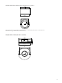
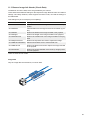
5.2 Lens Mount Adapter
Notice
LXG-20 and LXG-40 have a C-Mount interface only.
Adapter M58 / F-Mount (Art. No.: 11117852)
59ø
40,43
F-Mount
M58x0,75
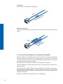
Adapter M58 / M42x1-Mount (26.8mm) (Art. No.: 11127232)
20,75
59ø
M58x0,75
M42x1
3
ø
50
Notes:
ange focal distance: 27 mm, ±0,25 mm
suitable for Zeiss M42 lenses (e.g. Biogon T* 2.8/21 Z-M42-I, Biogon T* 2/35 Z-M42-I, C Sonnar T* 1.5/50 Z-M42-I)

11
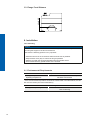
Adapter M58 / M42x1-MOUNT (45.5 mm) (Art. No: 11137781)
39,43
59ø
M58x0,75
M42x1
3
ø
50
Noce: suitable for Zeiss (e.g. Distagon T* 2/25 Z-M42-I, Planar T* 1.4/50 Z-M42-I, Makro-Planar T* 2/50 Z-M42-I) and
KOWA M42 lenses (e.g. LM28LF P-Mount, LM35LF P-Mount)
Adapter M58 / C-Mount (Art. No: 11115198)
C-Mount
M58x0,75
59ø
30ø
4,467
3ø
50

12
5.3 Flange Focal Distance
12 ±0,25
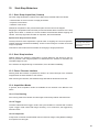
6. Installation
Lens mounting
Notice
Avoid contamination of the sensor and the lens by dust and airborne particles when
mounting the support or the lens to the device!
Therefore the following points are very important:
▪ Install the camera in an environment that is as dust free as possible!
▪ Keep the dust cover (foil) on camera as long as possible!
▪ Hold the print with the sensor downwards with unprotected sensor.
▪ Avoid contact with any optical surface of the camera!
6.1 Environmental Requirements
Temperature
Storage temperature -10 °C ... +70 °C ( +14 °F ... +158 °F)
Operating temperature* see Heat Transmission
* If the environmental temperature exceeds the values listed in the table below, the cam-
era must be cooled. (see Heat Transmission)
Humidity
Storage and Operating Humidity 10 % ... 90 %
Non-condensing

13
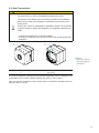
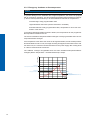
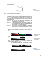
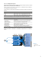
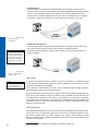
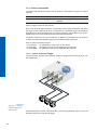
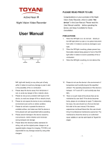
6.2 Heat Transmission
Caution
Provide adequate dissipation of heat, to ensure that the temperature does
not exceed +50 °C (+122 °F) at temperature measurment point T.
The surface of the camera may be hot during operation and immediately
after use. Be careful when handling the camera and avoid contact over a
longer period.
As there are numerous possibilities for installation, Baumer do not speciy
a specic method for proper heat dissipation, but suggest the following prin-
ciples:
▪ operate the cameras only in mounted condition
▪ mounting in combination with forced convection may provide proper heat
dissipation
T
T
Measure Point Maximal Temperature
T 60°C (140°F)
For remote temperature monitoring of the camera a temperature sensor is integrated. The
temperature sensor is able to deliver values of 0°C (32°F) to +85°C (185°F)
Take care that the temperature of the camera does not exceed the specied case tem-
perature +60°C (+140°F).
◄Figure2
Temperature measure-
ment points of Baumer
LXG cameras.

14
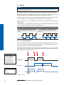
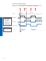
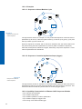
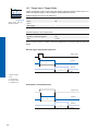
6.2.1 Emergency shutdown at Overtemperature
Notice
Feature only available on the LXG-250, LXG-500.
To prevent damage on the hardware due to high temperatures, the camera is equipped
with an emergency shutdown. The DeviceTemperatureStatusTransitionSelector (Catego-
ry: Device Control) feature allows you to select dierent thresholds for temperatures:
NormalToHigh: freely programmable value
HighToExeeded: xed value (camera shutdown if exceeded)
ExeededToNormal: freely programmable value, temperature for error-free re-ac
tivation of the camera.
In the DeviceTemperatureStatusTransition feature, the temperatures for the programma-
ble temperature transitions are set.
The Event EventDeviceTemperatureStatusChanged is always generated when Device-
TemperatureStatus changes.
If the temperature rises above the value set at HighToExeeded, the DeviceTemperature-
Exceeded feature is set to True, the image recording is stopped, and the LED is set to red.
For further use, the camera must disconnected from the power supply after cooling down
or a device reset should be carried out.
The sucient cooling is recognizable when the event EvenDeviceTemperatureStatus-
Changed (Device Temperature < ExceededToNormal) is output.
NormalToHigh
freely programmable value
HighToExeed
fixed value (camera shutdown if exceeded)
ExeedToNormal
(Device Temperature < ExceededToNormal)
freely programmable value
Time
Temperature
Event:DeviceTemperature-
StatusChanged
Event:DeviceTemperature-
StatusChanged
Event:DeviceTemperature-
StatusChanged

15
6.3 Mechanical Tests
Tested with C-Mount adapter adapter and lens dummy.
Environmental
Testing
Standard Parameter
Vibration,
sinussodial
IEC 60068-2-6 Search for
Resonance
10-2000 Hz
Amplitude un-
derneath cross-
over frequencies
0,75 mm
Acceleration 1 g
Test duration 15 min (axis)
45 min (total)
Vibration, broad
band
IEC 60068-2-64 Frequency
range
10-1000 Hz
Acceleration 10 g
Test duration 300 min (axis)
15 h (total)
Shock IEC 60068-2-27 Puls time 11 ms / 6 ms
Acceleration 50 g / 100 g
Bump IEC60068-2-29 Pulse Time 2 ms
Acceleration 100 g

16
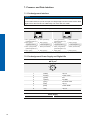
7. Process- and Data Interface
7.1 Pin-Assignment Interface
Notice
Only Port 1 (at the top) supports Power over Ethernet (36 VDC .. 57 VDC).
For the data transfer, the ports are equal. For Single GigE connect one Port and for Dual
GigE connect the second Port additionally. The order does not matter.
Data / Control 1000 Base-T (Port 1) Data / Control 1000 Base-T (Port 2)
LED2
LED1
8
1
LED2
LED1
8
1
1 MX1+ (green/white)
(negative/positive V
port
)
5 MX3- (blue/white) 1 MX1+ (green/white)
(negative/positive V
port
)
5 MX3- (blue/white)
2 MX1- (green)
(negative/positive V
port
)
6 MX2- (orange)
(positive/negative V
port
)
2 MX1- (green)
(negative/positive V
port
)
6 MX2- (orange)
(positive/negative V
port
)
3 MX2+ (orange/white)
(positive/negative V
port
)
7 MX4+ (brown/white) 3 MX2+ (orange/white)
(positive/negative V
port
)
7 MX4+ (brown/white)
4 MX3+ (blue) 8 MX4- (brown) 4 MX3+ (blue) 8 MX4- (brown)
7.2 Pin-Assignment Power Supply and Digital-IOs
Power Supply / Digital-IOs
M8 / 8 pins
8
5
7
3
1
4
2
6
1 (white) OUT 3
2 (brown) Power VCC +
3 (green) IN 1
4 (yellow) IO GND
5 (grey) IO Power VCC
6 (pink) OUT 1
7 (blue) Power GND
8 (red) OUT 2
Power Supply
Power VCC 12 VDC ... 24 VDC

17
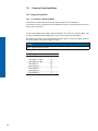
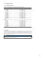
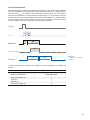
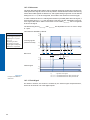
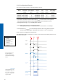
7.3 Power saving Mechanisms
The camera is equipped with various power saving mechanisms to reduce the power
consumption and to prevent excessive heating.
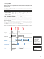
1. Set the sensor into idle state (LXG-250 only)
If no frame is requested for a specic time (idle time), the sensor is set into idle state. This
reduces the power consumption of the camera.
The sensor is not set into idle state:
▪ in Sequencer Mode
▪ in Burst Mode
▪ at set Acquisition Frame Rate
Trigger (valid)
Exposure
Readout
Time
A
B
C
Idle
DD
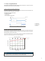
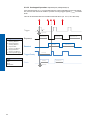
2. Dynamic adjustment of the framerate (all models)
The frame rate is dynamically adjusted to the current situation. This means that only so
many frames are recorded, as can be transferred via the interface with the current set-
tings (resolution, binning, pixel format).
This dynamic adjustment only works when the feature Acquisition Frame Rate is deacti-
vated, so the camera takes pictures at FreeRunning Mode.
0510 15 20 25
4
5
6
7
8
9
10
framerate [fps]
Power saving diagram
power consumption [W]
without power saving
with power saving
Notice
The diagram applies for a low exposure time. As the exposure time increases, the pow-
er consumption of the camera increases even with small framerate.
A - Trigger delay
B - Exposure time
C - Readout time
D - Idle time

18
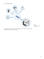
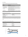
7.4 LED Signaling
LED
Signal Meaning
LED
green on Power on, link good
green blinking Power on, no link
red on Error / Overtemperature
red blinking
Warning
(update in progress, don’t switch o)
yellow Readout active
Figure3►
LED positions on Baumer LXG
cameras.

19
8. ProductSpecications
8.1 SensorSpecications
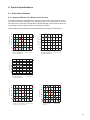
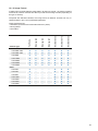
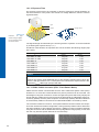
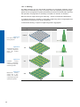
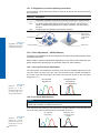
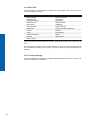
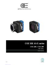
8.1.1 QuantumEciencyforBaumerLXGCameras
The quantum eciency characteristics of monochrome and color matrix sensors for Bau-
mer LXG cameras are displayed in the following graphs. The characteristic curves for
the sensors do not take the characteristics of lenses and light sources without lters into
consideration, but are measured with an AR coated cover glass.
Values relating to the respective technical data sheets of the sensors manufacturer.
350 450 550 650 750 850 950 1050
Wave Length [nm]
Quantum Efficiency [%]
LXG-20C (CMV2000 V3)
LXG-40C (CMV4000 V3)
Red
Green
Blue
350 450 550 650 750 850 950 1050
Wave Length [nm]
Quantum Efficiency [%]
LXG-20M (CMV2000 V3)
LXG-40M (CMV4000 V3)
MonoMono
400 500 600 700 800 900 1000
0
Wave Length [nm]
LXG-20NIR (CMV2000 V3)
LXG-40NIR (CMV4000 V3)
NIR
Quantum Efficiency [%]
70
80
90
350450 550650 750850 9501050
Wave Length [nm]
Quantum Efficiency [%]
LXG-80M / LXG-80C (CMV8000)
LXG-120M / LXG-120C (CMV12000)
Mono
Red
Green
Blue
350450 550650 750850 9501050
Wave Length [nm]
Quantum Efficiency [%]
LXG-200M / LXG-200C
(CMV20000)
Mono
Red
Green
Blue
70

20
LXG-250M / LXG-250C
(Python 25K)
Mono
Red
Green
Blue
300 400 500 600 700 800 900 1000 1100
Wave Length [nm]
Quantum Efficiency [%]
350 450 550 650 750 850 950 1050
Wave Length [nm]
Quantum Efficiency [%]
LXG-500M / LXG-500C
(CMV-50000)
Mono
Red
Green
Blue
70
350 450 550 650 750 850 950 1050
Wave Length [nm]
Quantum Efficiency [%]
LXG-500M
(CMV-50000)
Mono
70
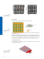
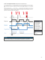
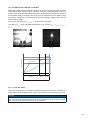
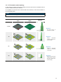
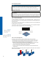
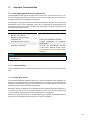
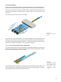
8.1.2 Shutter
All cameras of the LXG series are equipped with a global shutter.
Pixel
Active Area (Photodiode)
Storage Area
Microlens
Global shutter means that all pixels of the sensor are reset and afterwards exposed for a
specied interval (t
exposure
).
For each pixel an adjacent storage circuit exists. Once the exposure time elapsed, the
information of a pixel is transferred immediately to its circuit and read out from there.
Due to the fact that photosensitive area gets "lost" by the implementation of the circuit
area, the pixels are equipped with microlenses, which focus the light on the pixel.
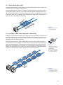
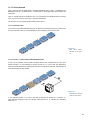
8.1.3 Digitization Taps
The CMOSIS sensors, employed in Baumer LXG cameras are read out with 16 (LXG-
500: 11) channels in parallel.
Figure4►
Quantum eciency for
Baumer LXG cameras.
Figure5►
Structure of an imag-
ing sensor with global
shutter
Figure6►
Digitization Tap of the
Baumer LXG cameras
Readout with 16 chan-
nel
Page is loading ...
Page is loading ...
Page is loading ...
Page is loading ...
Page is loading ...
Page is loading ...
Page is loading ...
Page is loading ...
Page is loading ...
Page is loading ...
Page is loading ...
Page is loading ...
Page is loading ...
Page is loading ...
Page is loading ...
Page is loading ...
Page is loading ...
Page is loading ...
Page is loading ...
Page is loading ...
Page is loading ...
Page is loading ...
Page is loading ...
Page is loading ...
Page is loading ...
Page is loading ...
Page is loading ...
Page is loading ...
Page is loading ...
Page is loading ...
Page is loading ...
Page is loading ...
Page is loading ...
Page is loading ...
Page is loading ...
Page is loading ...
Page is loading ...
Page is loading ...
Page is loading ...
Page is loading ...
Page is loading ...
Page is loading ...
Page is loading ...
Page is loading ...
Page is loading ...
Page is loading ...
Page is loading ...
Page is loading ...
Page is loading ...
Page is loading ...
Page is loading ...
Page is loading ...
Page is loading ...
Page is loading ...
-
 1
1
-
 2
2
-
 3
3
-
 4
4
-
 5
5
-
 6
6
-
 7
7
-
 8
8
-
 9
9
-
 10
10
-
 11
11
-
 12
12
-
 13
13
-
 14
14
-
 15
15
-
 16
16
-
 17
17
-
 18
18
-
 19
19
-
 20
20
-
 21
21
-
 22
22
-
 23
23
-
 24
24
-
 25
25
-
 26
26
-
 27
27
-
 28
28
-
 29
29
-
 30
30
-
 31
31
-
 32
32
-
 33
33
-
 34
34
-
 35
35
-
 36
36
-
 37
37
-
 38
38
-
 39
39
-
 40
40
-
 41
41
-
 42
42
-
 43
43
-
 44
44
-
 45
45
-
 46
46
-
 47
47
-
 48
48
-
 49
49
-
 50
50
-
 51
51
-
 52
52
-
 53
53
-
 54
54
-
 55
55
-
 56
56
-
 57
57
-
 58
58
-
 59
59
-
 60
60
-
 61
61
-
 62
62
-
 63
63
-
 64
64
-
 65
65
-
 66
66
-
 67
67
-
 68
68
-
 69
69
-
 70
70
-
 71
71
-
 72
72
-
 73
73
-
 74
74


Ask a question and I''ll find the answer in the document
Finding information in a document is now easier with AI
Related papers
-
Baumer LXG-20M.PS User guide
-
Baumer HXG40c User guide
-
Baumer VLG-22C.I User guide
-
Baumer VLG-20M User guide
-
Baumer MXGC20c User guide
-
-
-
-
Baumer DLM20-BU Installation and Operating Instructions
-
Baumer LXG-200C Quick start guide
Other documents
-
Paasche LXG-14 User manual
-
 SVS-Vistek eco415 User manual
-
 Toyani TA-JY500 User manual
-
JAI SW-2000M-CL-65 User manual
-
 opto engineering COE-290 User manual
-
Axis Communications 5504-951 User manual
-
 Process Sensors MCT466-QC User Manual Manual
-
Quantum Vision Quick start guide
-
AMS CMV4000 EVALUATION KIT User guide
-
Zeiss Axiocam 512 color User manual


