
Product Specication
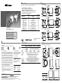
TXG series – Innovative functionality in compact design
Output of excellent 8 / 12 bit image data
VGA up to 5 megapixel, monochrome and color
RGB and YUV interpolation algorithms on board
Bandwidth up to 1000 Mbit/sec for fast multi-camera operation
Flexible system architecture due to cable length up to 100 m
Baumer driver for reliable image transfer
Camera Type
Sensor
Size
Resolution
Full Frames
[max. fps]
Monochrome / Color
TXG02 / TXG02c 1/4“ 656x494 140
TXG03 / TXG03c 1/3" 656 x 494 / 656 x 490 90
TXG04 1/2" 656 x 494 56
TXG06 / TXG06c 1/2" 776 x 582 / 776 x 578 64
TXG08 / TXG08c 1/3" 1032 x 776 / 1032 x 772 28
TXG12 / TXG12c 1/3“ 1296x966 32
TXG13 / TXG13c 1/2" 1392 x 1040 / 1384 x 1036 20
TXG14 / TXG14c 2/3" 1392 x 1040 / 1384 x 1036 20
TXG14f 2/3" 1392 x 1040 30
TXG20 / TXG20c 1/1.8" 1624 x 1236 / 1624 x 1232 16
TXG50 / TXG50c 2/3" 2448 x 2050 / 2448 x 2050 15
System Requirements
Single-camera system Multi-camera system
Minimum Recommended Minimum Recommended
CPU
Intel
®
Pentium
®
4
or comparable
processor
Intel
®
Core™ Duo comparable processor
Clock
2.5 GHz > 2.5 GHz 2.5 GHz 3 GHz
RAM
1024 MB 2048 MB 2048 MB > 2048 MB
Operating
system
(OS)
Microsoft
®
Windows
®
XP incl. Service Pack 2 or higher
Microsoft
®
Windows
®
XP x64 incl. Service Pack 2 or higher
Microsoft
®
Windows Vista™ 32 / 64 bit systems
Microsoft
®
Windows 7 32 / 64 bit systems
Linux
®
32 / 64 bit systems from Kernel 2.6.xx
Graphic
recommended resolution 1280 x 1024, color depth at least 16 bit
Ethernet
Gigabit Ethernet compliant NIC (recommended Intel
®
chipset)
Framework
(optional)
Windows
®
OS: .NET™ Framework 2.0 or higher
Linux
®
OS: Mono 1.2.4 or higher
Dimensions
56
56
4
x
M
5
C-Mount
62Mx 1,5
58,3
Ø 65
51,8 61,8
70,8 93,8
Ø
65
Dimensions
26
26
36
36
4
x
M
3
36
36
26
8
x
M
3
48
C-Mount 6,5
26
26
36
36
4
x
M
3
36
36
26
8
x
M
3
57,7
C-Mount 6,5
26
26
36
36
4
x
M
3
36
36
26
8
x
M
3
48
C-Mount 6,5
Safety
Further Information
For further information on our products visit www.baumer.com
For technical issues, please contact our technical support:
support.cameras@baumer.com · Phone +49 (0)3528 4386-0 · Fax +49 (0)3528 4386-86
© Baumer Optronic GmbH · Badstrasse 30 · DE-01454 Radeberg, Germany
Technical data has been fully checked, but accuracy of printed matter not guaranteed.
Subject to change without notice. Printed in Germany 01/20. v48 11037533
FCC – Class B device
N: This equipment has been tested and found to
comply with the limits for a Class B digital device, pursu-
ant to part 15 of the FCC Rules. These limits are designed
to provide reasonable protection against harmful interfer-
ence in a residential environment. This equipment gener-
ates, uses, and can radiate radio frequency energy and, if
not installed and used in accordance with the instructios,
may cause harmful interference to radio communications.
However, there is no guarantee that interference will not
occure in a particular installation. If this equipment does
cause harmful interference to radio or television reception,
on, the user is encouraged to try to correct the interference
by one or more of the following measures:
Reorient or relocate the receiving antenna.
Increase the separation between the equipment and the
receiver.
Connect the equipment into an outlet on a circuit different
from that to which the receiver is connected.
Consult the dealer or an experienced radio/TV technician
for help.
Conformity:
CE, FCC Part 15 Class B, UL (standard cameras only), RoHS
UL – Class III device
The power supply to operate the
TXG series of cameras must be real-
ized using a limited power supply in
accordance to UL60950.
Safety Precautions
Protect the sensor from dirt and
moisture.
Never open the camera housing.
Avoid camera contamination by
foreign objects.
Environmental requirements:
Storage temp. -10°C ... +70°C
Operating temp. +5°C ... +50°C
Housing temp. max. +50°C
Humidity 10 % ... 90 %
Non-condensing
Tested according to standard
EMVA 1288
Quick Start Guide
TXG Cameras (Gigabit Ethernet)
Tube Length
[mm]
Item No.
51,8 11008777
61,8 11008776
70,8 11008775
93,8 11008774
Download latest camera software:
www.baumer.com/vision/software
Download latest technical documentation:
www.baumer.com/cameras/docs

LED Signaling
LEDs of camera types:
Camera Type 2 LEDs 3 LEDs
Standard
PoE
IP
I/O
1
1
2
3
2
2 LEDs Signal Meaning
1
green Power on
yellow Readout active
2
green Link active
Receiving
yellow Transmitting
Receiving and Transmitting
3 LEDs Signal Meaning
1
green Power on
yellow Readout active
2
green Link active
Receiving
3 red Transmitting
Process and Data Interfaces
Interfaces of camera types:
Camera
Type
8P8C
mod jack
8P8C
mod jack
LED
M12
8 pins
M8
3 pins
M8
4 pins
M8
8 pins
Standard
PoE
IP67
IO
Gigabit Ethernet Interfaces
8P8C mod jack 8P8C mod jack with LED M12 8 pins
18
18
8
5
73
1
4
2
6
8
5
73
1
4
2
6
7
1 (gn/wh) MX1+ 1 (gn/wh) MX1+ (neg. / pos. V
port
) 1 (wh) MX3-
2 (gn) MX1- 2 (gn) MX1- (neg. / pos. V
port
) 2 (bn) MX4+
3 (og/wh) MX2+ 3 (og/wh) MX2+ (pos. / neg. V
port
) 3 (gn) MX4-
4 (bu) MX3+ 4 (bu) MX3+ 4 (ye) MX1-
5 (bu/wh) MX3- 5 (bu/wh) MX3- 5 (gr) MX2+
6 (og) MX2- 6 (og) MX2- (pos. / neg. V
port
) 6 (pk) MX1+
7 (bn/wh) MX4+ 7 (bn/wh) MX4+ 7 (bu) MX3+
8 (bn) MX4- 8 (bn) MX4- 8 (rd) MX2-
Mounting Adapters
For Standard Cameras:
Name Item-No.
Tripod mounting adapter 11003060
Front mounting adapter 11002638
For Cameras with IP67 housing:
Name Item-No.
IP mounting Adapter 11003947
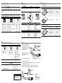
Installation
Installation of standard cameras:
Connect the camera using an
appropriate cable (at least Cat-
5e) to the GigE board on your
PC (8P8C mod jack)
If required, connect a trigger
and / or flash to the 4-pin M8
male connector
Connect the camera to power supply
Installation of cameras with PoE:
Connect the camera using an appropriate cable (at least Cat-5e) to a free port of a
PoE capable ethernet switch
Establish the connection between switch and GigE board on your PC
If required, connect a trigger and / or flash to the 4-pin M8 male connector
open wire
Interfaces for Power Supply and Digital IOs
M8 3 pins M8 4 pins M8 8 pins
1
4
3
1
2
4
3
8
5
73
1
4
2
6
8
5
73
1
4
2
6
7
1 (brown) Power V
CC
1 (brown) TrigIN+ 1 (white) Out 3
3 (blue) GND 2 (white) TrigIN- 2 (brown) In 2
4 (black) NC 3 (blue) Flash
out
3 (green) In 1
4 (black) U
ext
4 (yellow) IO GND
5 (grey) IO Power V
CC
6 (pink) Out 1
7 (blue) Out 2
8 (red) In 3
Power Supply
Power V
CC
8 V DC ... 30 V DC
I 620 mA ... 120 mA
Power consumption P approx. 3.5 ... 6 W
Installation sample
1 - PCI board; 2 - GigE cable;
Installation sample
1 - PCI board;
2 - GigE cable;
3 - PoE capable ethernet switch
or Baumer PoE components;
Notice
Further technical details
available in the respective
data sheets.
open wir
e
-
 1
1
-
 2
2


Ask a question and I''ll find the answer in the document
Finding information in a document is now easier with AI
in other languages
Related papers
-
Baumer TXG20c Quick start guide
-
Baumer MXGC20c Quick start guide
-
Baumer VLG-20M Quick start guide
-
-
Baumer VEXG-52M.R Quick start guide
-
Baumer VCXG-13C Quick start guide
-
-
Baumer VLXT-123M.FO Quick start guide
-
Baumer EXG50 Quick start guide
-
Other documents
-
CableWholesale SR-8P8C-GY Datasheet
-
Moxa VPORT 16-DO-M12-CAM3L5430P User manual
-
AUSTRALIAN MONITOR TXG50 Operating instructions
-
AOpen MX33 User manual
-
-
Trixie Alicante User manual
-
Microscan Visionscape GigE Integrated Vision Solution User manual
-
Avanity SUT49GB-R Installation guide
-
Datalogic M565 Owner's manual
-
Moxa Technologies Vport P16-1MP-M12-IR-CAM80 Quick Install Guide