
1
˚C
Installation and user manual
EFIT™ 850 controller
GB-DAS

2
1: User Manual
System overview . . . . . . . . . . . . . . . . . . . . . . . . . . . . . . . . . . . . . . . . . . . . . . . . 3
General use . . . . . . . . . . . . . . . . . . . . . . . . . . . . . . . . . . . . . . . . . . . . . . . . . . . 5
Buttons . . . . . . . . . . . . . . . . . . . . . . . . . . . . . . . . . . . . . . . . . . . . . . . . . 5
Display. . . . . . . . . . . . . . . . . . . . . . . . . . . . . . . . . . . . . . . . . . . . . . . . . . 5
Menu system. . . . . . . . . . . . . . . . . . . . . . . . . . . . . . . . . . . . . . . . . . . . . . 6
Possible alarms during operation
Clogged drain . . . . . . . . . . . . . . . . . . . . . . . . . . . . . . . . . . . . . . . . . . . . . 7
Missing sensor . . . . . . . . . . . . . . . . . . . . . . . . . . . . . . . . . . . . . . . . . . . . . 7
New added sensor . . . . . . . . . . . . . . . . . . . . . . . . . . . . . . . . . . . . . . . . . . 7
Sensor malfunction. . . . . . . . . . . . . . . . . . . . . . . . . . . . . . . . . . . . . . . . . . 7
Changing parameters and performance of systems. . . . . . . . . . . . . . . . . . . . . . . . . . 8
Roof system . . . . . . . . . . . . . . . . . . . . . . . . . . . . . . . . . . . . . . . . . . . . . . 8
Ground system . . . . . . . . . . . . . . . . . . . . . . . . . . . . . . . . . . . . . . . . . . . . 9
2: Installer Manual
System overview . . . . . . . . . . . . . . . . . . . . . . . . . . . . . . . . . . . . . . . . . . . . . . . 10
Placement . . . . . . . . . . . . . . . . . . . . . . . . . . . . . . . . . . . . . . . . . . . . . . . . . . . 11
Connection steps for system . . . . . . . . . . . . . . . . . . . . . . . . . . . . . . . . . . . . . . . 11
Installation steps for system/systems . . . . . . . . . . . . . . . . . . . . . . . . . . . . . . . . . . 15
General . . . . . . . . . . . . . . . . . . . . . . . . . . . . . . . . . . . . . . . . . . . . . . . . 15
Installation of roof system . . . . . . . . . . . . . . . . . . . . . . . . . . . . . . . . . . . . 16
Installation of ground system . . . . . . . . . . . . . . . . . . . . . . . . . . . . . . . . . . 17
Installation of combi system . . . . . . . . . . . . . . . . . . . . . . . . . . . . . . . . . . . 18
Installation of dual system . . . . . . . . . . . . . . . . . . . . . . . . . . . . . . . . . . . . 20
Modification of system(s) . . . . . . . . . . . . . . . . . . . . . . . . . . . . . . . . . . . . . . . . . 22
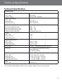
3: Technical Specification
Technical data . . . . . . . . . . . . . . . . . . . . . . . . . . . . . . . . . . . . . . . . . . . . . . . . 25
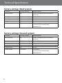
Factory settings (Roof system) . . . . . . . . . . . . . . . . . . . . . . . . . . . . . . . . . . . . . . 26
Factory settings (Ground system) . . . . . . . . . . . . . . . . . . . . . . . . . . . . . . . . . . . . 26
4: Appendix . . . . . . . . . . . . . . . . . . . . . . . . . . . . . . . . . . . . . . . . . . . . . :
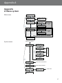
A: Menu system. . . . . . . . . . . . . . . . . . . . . . . . . . . . . . . . . . . . . . . . . . . . . . . . 27
B: How it works . . . . . . . . . . . . . . . . . . . . . . . . . . . . . . . . . . . . . . . . . . . . . . . . 32
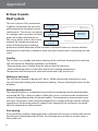
Roof system . . . . . . . . . . . . . . . . . . . . . . . . . . . . . . . . . . . . . . . . . . . . . 32
Ground system . . . . . . . . . . . . . . . . . . . . . . . . . . . . . . . . . . . . . . . . . . . 33
Security and energy consumption . . . . . . . . . . . . . . . . . . . . . . . . . . . . . . . 34
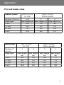
C: PSU and feeder cable . . . . . . . . . . . . . . . . . . . . . . . . . . . . . . . . . . . . . . . . . . 35
Ground system . . . . . . . . . . . . . . . . . . . . . . . . . . . . . . . . . . . . . . . . . . . 35
Roof system . . . . . . . . . . . . . . . . . . . . . . . . . . . . . . . . . . . . . . . . . . . . . 35
Table of Contents

User Manual
3
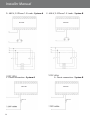
System overview
The EFIT™ 850 system is capable of keeping outdoor areas free of ice and snow.
The EFIT™ 850 can handle up to 2 independent areas, in any of the following
combinations:
•Singleroofsystem
To keep gutters, valley gutters and down pipes
free of ice and snow, and to prevent icicles from
causing damage. It is also possible to use the roof
system to reduce/remove the snow weight from
a roof. (Roof system A)
•Singlegroundsystem
To keep areas like parking areas, paths, garage
entrances, steps, ramps, roadways and bridges
free of ice and snow. (Ground systems A)
•1groundsystemand1roofsystem
(combi system)
Consists of 1 single roof system A and 1 single
ground system B.
•2roofsystems (dual system)
Consists of 2 x “Single roof systems (A and B)”.
•2groundsystems (dual system)
Consists of 2 x “Single ground systems (A and B)”.
A
A
A
A
B
B
B
A
A
B

4
User Manual
When more than 1 area is controlled by the EFIT™ 850 system, it is also possible to
prioritize the areas. Prioritizing makes it possible to operate 2 areas, even if the needed
power for 2 areas is not present.
The EFIT™ 850 is fully automatic and operated digitally by means of the intelligent sen-
sors located in the heated terrain. Each sensor measures both temperature and mois-
ture, and the system turns the heating elements on and off based on these readings. By
combining moisture and temperature readings, the system is able to save around 75%
energy compared to systems which only measure temperature readings. The digital
sensors used for the EFIT™ 850 also provide the most exact readings when compared
with corresponding analogue systems. The result is optimum functionality and low
energy consumption.
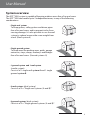
A typical installation consists of:
• Controller unit (only one)
This is the device which, based on the measure-
ments from the sensors, decides when to heat the
connected area(s).
•Power supply (one or more)
The power supply delivers power to the controller
unit and the connected sensors.
• Ground sensor (one or more)
At least 1 ground sensor is needed for each
ground area, but to get the best performance of a
system, 2 or more sensors are recommended.
For more information please refer to the sensor
manual.
•Roofsensor (one or more)
At least 1 roof sensor is needed for each roof area,
but for complex roof constructions, 2 or more sen-
sors are recommended.
For more information please refer to the sensor
manual.
For more information about the ice and snow melting function of the EFIT™ 850, please
refer to: Appendix B: “How it works”.

User Manual
5
General use
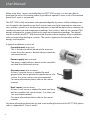
The EFIT™ 850 is operated via 3 buttons and an alpha numeric display capable of dis-
playing information in various languages.
Buttons
The functions of the 3 buttons are:
Info Shows additional information / help (Only active when lit)
Next Next menu entry / next line / next letter
Enter Confirm / select
Besides the normal function of the buttons, some special combinations are important
to the user:
Return to home: Hold for 2 seconds:
Return to home of menu system
Master reset: Hold for 8 seconds:
Restore factory defaults AND delete installed systems.
(In case of insolvable problems due to a wrong choice of
language, etc.)
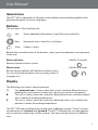
Display
The following icons have a special meaning:
This animated icon is shown, when the system is heating. When the icon is
blinking the system wants to heat, but is paused (system has low priority)
This icon is shown, when the system has detected moisture, and the tempera-
ture is above the melting temperature.
This icon is shown, when the system has detected snow or ice, and the tem-
perature is below the melting temperature.
The EFIT™ 850 can simultaneously control up to 2 different systems. These 2 systems
are referred to as System A and System B. The EFIT™ 850 gives the user the opportu-
nity to view the current status of the systems. The status can be shown in 2 different
ways.
+

6
User Manual
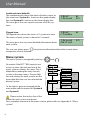
Combinedview(default):
The combined view shows the status of both systems at
the same time. System A is shown on the upper display
line, and System B is shown on the lower display line.
This view gives the user a quick overview of all the sys-
tems.
Flipped view:
The flipped view shows the status of 1 system at a time.
The status of each system is shown for 5 seconds.
This view gives the user more detailed information about
each system.
The user can always press to get more information about the current status
irrespective of view selected.
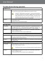
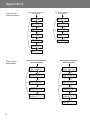
Menu system
The menu system is navigated by the keys and .
No matter if the EFIT™ 850 controls one
or two systems, the look and use of the
menu system is always the same. This is
obtained by making the entry to each
system in the main menu. The possibili-
ties and settings for each system are first
accessible after the user has selected the
desired system.
To the right is given an example of the
main menu and the menus for System A
and System B.
Please notice, that only a few of the
menus for each system are shown!
For a complete overview of the menu system, please refer to: Appendix A: “Menu
system”.
A:Roof
B:Ground
A:Roof
>>
Standby
B:Ground
>>
Melting
S ys tem
B
S ys tem
A
A:Roof˜
ÚStandby
B:Ground¯ˆı
ÚMelting
Selectsystem A:
Roof
Selectsystem B:
Ground
Viewalarm
menu
5s
A:Roof˜
B:Ground¯ˆı
5s
Viewandset
operatingmode
Viewsensor
measurements
Viewandset
operatingmode
Viewsensor
measurements
Only visible when S ystem B is ins talled!
A:Roof˜
ÚStandby
B:Ground¯ˆı
ÚMelting
SelectsystemA:
Roof
SelectsystemB:
Ground
Viewalarm
menu
5s
A:Roof˜
B:Ground¯ˆı
5s
Only v is ible whe n
S ys tem B is ins talled!
S ys tem menu
(S ys tem A)
A:Roof˜
B:Ground¯ˆı
S ys tem menu
(S ys tem B)

User Manual
7
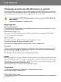
Possiblealarmsduringoperation
Cloggeddrain
Description: When clogged drain warning has been enabled, an alarm is raised when
the system constantly has been detecting moisture for 14 days.
If the EFIT™ 850 controls more than 1 system, and prioritizing
has been enabled, the time before clogged drain warning for the
down-prioritized system, can be much longer. The time is only
updated, when the system actually is allowed to heat the area
(e.g. the up-prioritized system is not heating)
Solution: - Check gutter and down pipes for any obstacles preventing the melting
water to flow away.
- Check if sensors are covered with dirt.
Missingsensor
Description: When the connection to a sensor is lost, the EFIT™ 850 alarms the user. At
the same time the EFIT™ 850 automatically switches the system to “Con-
stant Off” mode, and user interaction with the EFIT™ 850 is needed.
Solution: - Acknowledge error and go to “Installer Site” in the menu system and
select “Change System”.
- Contact your local installer to get a replacement.
New sensor added
Description: When a new sensor is added, the EFIT™ 850 alarms the user and at the
same time automatically switches to “Constant Off” mode. User interaction
is needed in order to correct the error.
Solution: Acknowledge error and go to “Installer Site” in the menu system and select
“Change System”.
Sensormalfunction
Description: When something is wrong with the readings from connected sensors to
the EFIT™ 850, an alarm is raised.
Not all error prone sensors can be discovered using this feature!
Solution: - Acknowledge error and go to “Installer Site” in the menu system and
select “Change System”.
- Contact your local service centre to get a replacement.
S ys tem
B
S ys tem
A
A:Roof˜
ÚStandby
B:Ground¯ˆı
ÚMelting
Selectsystem A:
Roof
Selectsystem B:
Ground
Viewalarm
menu
5s
A:Roof˜
B:Ground¯ˆı
5s
Viewandset
operatingmode
Viewsensor
measurements
Viewandset
operatingmode
Viewsensor
measurements
Only visible when S ystem B is ins talled!
A:Roof˜
ÚStandby
B:Ground¯ˆı
ÚMelting
SelectsystemA:
Roof
SelectsystemB:
Ground
Viewalarm
menu
5s
A:Roof˜
B:Ground¯ˆı
5s
Only v is ible whe n
S ys tem B is ins talled!
S ys tem menu
(S ys tem A)
A:Roof˜
B:Ground¯ˆı
S ys tem menu
(S ys tem B)

8
User Manual
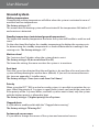
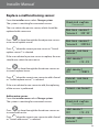
Changingparametersandperformanceofsystems
Several parameters for each system can be changed during and after the installation.
For a complete understanding of how these parameters affect the performance of the
roof and ground system, please refer to Appendix B: “How it works”.
OnlychangetheEFIT™850parametersifyouareawareoftheeectsof
your actions.
Reference: Appendix A: Installer menu
Roofsystem
Meltingtemperature
Changing the melting temperature will affect when the system is activated in case of
moisture and low temperatures.
The factory setting is 1.5°C.
This means that the heating system will be activated if the temperature falls below
1.5°C and moisture is detected.
Moisture level
The “moisture level” decides when the system detects moist.
The factory setting is 50 (on a scale from 5 to 95).
The lower the setting, the more sensitive the system is to moisture.
Post-heat
Once the sensor has detected that the roof/gutter is dry and free of ice and snow the
system will keep heating for another hour (default). If you wish to increase/decrease
this time see appendix A: Installer menu.
The factory setting is 1 hour (on a scale from 0 to 9 hours)
Priority
When using the EFIT™ 850 as a dual or combi system, it is possible to prioritize the sys-
tems. When the priority of 2 systems is equal, both systems can heat at the same time.
If the priority of the 2 systems differs, and both systems want to heat, only the system
with the highest priority is allowed to heat.
The factory setting is 1 (highest priority) for all systems.
Cloggeddrain
It is possible to enable and disable the “Clogged drain warning”.
The factory setting is “Warning On”.
System and sensor name
It is possible to change the names of the system and connected sensors (see appendix
A: Installer menu.

User Manual
9
Ground system
Meltingtemperature
Changing the melting temperature will affect when the system is activated in case of
moisture and low temperatures.
The factory setting is 4°C.
This means that the heating system will be activated if the temperature falls below 4°C
and moisture is detected.
Standbytemperature(maintainedgroundtemperature)
The higher the standby temperature the faster the system will be able to melt ice and
snow.
On the other hand the higher the standby temperature the higher the running costs.
So, determining the standby temperature is a trade-off between fast melting or low
running costs. The factory setting is -3 C°.
Moisture level
The “moisture level” decides when the system detects moist.
The factory setting is 50 (on a scale from 5 to 95).
The lower the setting, the more sensitive the system is to moisture.
Post-heat
Once the sensor has detected that the roof/gutter is dry and free of ice and snow the
system will keep heating for another hour (default). If you wish to increase/decrease
this time see appendix A: Installer menu.
The factory setting is 1 hour (on a scale from 0 to 9 hours)
Priority
When using the EFIT™ 850 as a dual or combi system, it is possible to prioritize the sys-
tems. When the priority of 2 systems is equal, both systems can heat at the same time.
If the priority of the 2 systems differs, and both systems want to heat, only the system
with the highest priority is allowed to heat.
The factory setting is 1 (highest priority) for all systems.
Cloggeddrain
It is possible to enable and disable the “Clogged drain warning”.
The factory setting is “Warning On”.
System and sensor name
It is possible to change the names of the system and connected sensors.

10
User Manual
Installer Manual
System overview
The EFIT™ 850 can handle up to 2 independent areas, in any of the following
combinations:
• Singleroofsystem
(1 system, 1-4 roof sensors)
• Singlegroundsystem
(1 system, 1-4 roof sensors)
• 1groundsystemand1roofsystem (combi system)
(2 systems, 2-4 sensors total, minimum 1 sensor per system)
• 2roofsystems (dual system)
(2 systems, 2-4 sensors total, minimum 1 sensor per system)
• 2groundsystems (dual system)
(2 systems, 2-4 sensors total, minimum 1 sensor per system)
When more than 1 area is controlled by the EFIT™ 850 system, it is also possible to
prioritize the areas. Prioritizing makes it possible to operate 2 areas, even if the needed
power for 2 areas is not present.
A typical ice and snow melting system consists of:
• EFIT™850
Only 1 EFIT™ 850 is allowed on the Devibus™
• Power supply
More power supplies can be connected in parallel (if needed)
Be aware of maximum number of sensors on each power supply
(Refer to Technical Specification for power demand of sensors)
• Groundand/orroofsensor(s)
Be aware of maximum number and cable length of sensors on each power supply
(Refer to sensor manual for a more detailed description)
Installer Manual

User Manual
11
Placement
The EFIT™ 850 and power supply are designed for DIN rail mounting. When mounting
please be aware of the following conditions:
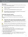
The EFIT™ 850 is designed and approved to operate in the temperature
range -10°C to 40°C.
The EFIT™ 850 is only IP20 protected, thus not water resistant.
The installer must ensure proper enclosure of the EFIT™ 850 according to
national standards (electrical safety).
Connectionstepsforsystem
Only authorized personnel is allowed to install the EFIT™ 850.
When wiring up the EFIT™ 850 and sensors, please be aware of the following
conditions:
When the EFIT™ 850 is used in a dual system configuration, it is preferable
that each sensor bus (devibus™) can be connected and disconnected via
switches. During the installation of a dual system, each system must be con-
nected one at a time.
Be aware of maximum allowable power drain from power supply to sensors.
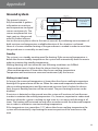
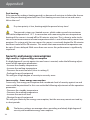
Below is shown the recommended order of the installation. Please refer to figure A for
connection of EFIT™ 850 and refer to figure B-G for a guideline to connect the heating
elements to EFIT™ 850.
1. Connect heating cables to the EFIT™ 850
• Please notice that a single system ALWAYS uses the System A output relay
• When using external power relay, please refer to the connection diagrams.
2. Connect the power supply to the EFIT™ 850
• Do not connect the power supply to mains yet
3. Connect sensors to the Devibus™
• When used as a dual system, only the sensors for System A can be connected. For
connection of System B please refer to chapter: “Installation of dual system”.
4. Connect the power supply to mains.
Installer Manual

12
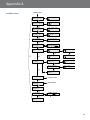
User Manual
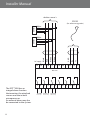
The EFIT™ 850 has an
integral alarm function
that monitors the attached
sensors and the in-built
microprocessor.
An external alarm may also
be connected to the system.
Installer Manual
EFIT™ 850
ALARM System A System B
250V~15Aμ250V~15Aμ250V~2Aμ
White
White
Red
Black
White
White
Red
Black
devibus sensor´s
White
White
Red
Black
DC supply
-
+
-
+
GND
Rx
Tx
RS232
(for software upgrades)
Sensor
Sensor
13 14 15 16 17 18 19 20 21 22 23 24
1 2 3 4 5 6 7 8 9 10 11 12

Installer Manual
13
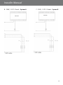
B - 230V, 1-3 P/1-3 loads - System A C - 230V, 1-3 P/1-3 loads - System B
EFIT™850
EFIT™850

14
Installer Manual
D - 400 V, 2-3 Phase/1-3 Loads - System A E - 400 V, 2-3 Phase/1-3 Loads - System B
F - Direct connection - System A G - Direct connection - System B
EFIT™850 EFIT™850
EFIT™850EFIT™850
MAX 15A
MAX 15A

Installer Manual
15
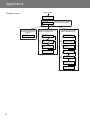
Installationstepsforsystem/systems
The installation of the EFIT™ 850 is very easy, and the user is guided through the instal-
lation process. The installation process differs a little depending on which kind and the
number of systems to be installed.
Please follow the general description and finally select the installation scenario accord-
ing to the system type.
Change setting with key:
Accept setting with key:
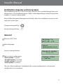
General
Power on EFIT™ 850
Select language
System is being checked…
Select system configuration
•Roofsystem (1 system)
•Groundsystem (1 system)
•Combisystem (2 systems)
•Dualsystem (2 systems)
The rest of the installation is divided into the system configurations; roof, ground,
combi or dual, as listed above.
Welcome to
EFIT 850 III
Select
language:English
Checking system
<------>
System size:
1 system

16
Connect sensors:
System A
System A
Scanning...
System type:
Roof
1 Roof sensor
found. Accept?
System A!
Installed
Checking system
<------>
Config system:
System A
Press Û to end
configuration.
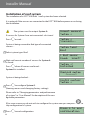
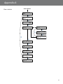
Installationofroofsystem
The installation of a EFIT™ 850 with 1 roof system has been selected.
It is optional if the sensors are connected to the EFIT™ 850 before power on or during
the installation.
The system uses the output System A.
If sensors for System A are not connected - do it now!
Press
or wait…
System is being scanned to find type of connected
sensors…
Select system type: Roof
Wait until correct number of sensors for System A
is found.
Press
when all sensors are found…
System A is installed…
System is being checked…
Press
to configure System A.
(Naming sensors and changing factory settings)
Please refer to “Changing parameters and performance
of systems” in “User Manual” for description of the con-
figurable parameters.
If for some reason you do not wish to configure the system now you can press
to
skip configuration of system .
Press
to end configuration.
Installer Manual

17
Connect sensors:
System A
System A
Scanning...
System type:
Ground
3 Ground sensor
found. Accept?
System A!
Installed
Config system:
System A
Press Û to end
configuration.
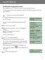
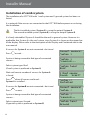
Installationofgroundsystem
The installation of a EFIT™ 850 with 1 ground system has been selected.
It is optional if the sensors are connected to the EFIT™ 850 before power on or during
the installation.
The system uses the output System A.
If sensors for System A are not connected - do it now!
Press
or wait…
System is being scanned to find type of connected
sensors…
Select system type: Ground
Wait until correct number of sensors for System A is
found.
Press
when all sensors are found…
System A is installed…
System is being checked…
Press
to configure System A.
(Naming sensors and changing factory settings)
Please refer to “Changing parameters and performance
of systems” in “User Manual” for description of the con-
figurable parameters.
If for some reason you do not wish to configure the
system now you can press
to skip configuration of
the system.
Press
to end configuration.
Checking system
<------>
Installer Manual

18
Installer Manual
Connect sensors:
System A
System A
Scanning...
System type:
Roof
1 Roof sensor
found. Accept?
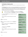
Installationofcombisystem
The installation of a EFIT™ 850 with 1 roof system and 1 ground system has been se-
lected.
It is optional if the sensors are connected to the EFIT™ 850 before power on or during
the installation.
The first installed system (System A) is using the output System A.
The second installed system (System B) is using the output System B.
It is freely selectable if System A should be the roof or ground system. However it is
preferable that System A is the roof system, since System A is shown on the upper line
of the display. Please refer to the description of the Display and Combined view in the
user manual.
If sensors for System A are not connected - do it now!
Press
or wait…
System is being scanned to find type of connected
sensors…
Select system type: Roof
(if roof system is preferred as System A)
Wait until correct number of sensors for System A
is found.
Press
when all sensors are found…
System A is installed…
If sensors for System B are not connected - do it now!
Press
or wait…
System is being scanned to find type of connected
sensors…
Select system type: Ground
(if ground system is preferred as System B)
Connect sensors:
System B
System B
Scanning...
System type:
Ground
System A!
Installed

Installer Manual
19
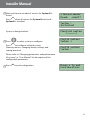
Press Û to end
Configuration.
Config system:
System B
Config system:
System A
Checking system
<------>
System B
Installed!
3 Ground sensors
found. Accept?
Wait until correct number of sensors for System B is
found.
Press
when all sensors for System B are found…
System B is installed…
System is being checked…
Press
to select system to configure.
Press
to configure selected system.
(Naming sensors, changing factory settings and
setting priorities)
Please refer to “Changing parameters and performance
of systems” in “User Manual” for description of the
configurable parameters.
Press
to end configuration.

20
Installer Manual
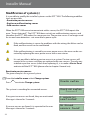
Installationofdualsystem
The installation of a EFIT™ 850 with 2 roof systems or 2 ground systems has been se-
lected.
It is mandatory that no sensors or only sensors for System A are connected to the the
EFIT™ 850 before power up. Sensors for System B must be connected to the EFIT™ 850
during the installation steps. Connection of the sensors during installation can either
be done using a switch on the DIN-rail or just connect sensor bus of System B to the
already connected sensor bus of System A.
The first installed system (SystemA) is using the output System A.
The second installed system (SystemB) is using the output System B.
If sensors for System A are not connected - do it now!
Press
or wait…
System is being scanned to find type of connected
sensors…
Select system type
Wait until correct number of sensors for System A is
found.
Press
when all sensors for System A are found…
System A is installed…
Connect sensors for System B.
Press
or wait…
System is being scanned to find type of connected
sensors…
Select system type
Connect sensors:
System A
System A
Scanning...
System type:
Ground
1 Ground sensor
found. Accept?
System A
Installed!
Connect sensors:
System B
System B
Scanning...
System type:
Ground
Page is loading ...
Page is loading ...
Page is loading ...
Page is loading ...
Page is loading ...
Page is loading ...
Page is loading ...
Page is loading ...
Page is loading ...
Page is loading ...
Page is loading ...
Page is loading ...
Page is loading ...
Page is loading ...
Page is loading ...
Page is loading ...
-
 1
1
-
 2
2
-
 3
3
-
 4
4
-
 5
5
-
 6
6
-
 7
7
-
 8
8
-
 9
9
-
 10
10
-
 11
11
-
 12
12
-
 13
13
-
 14
14
-
 15
15
-
 16
16
-
 17
17
-
 18
18
-
 19
19
-
 20
20
-
 21
21
-
 22
22
-
 23
23
-
 24
24
-
 25
25
-
 26
26
-
 27
27
-
 28
28
-
 29
29
-
 30
30
-
 31
31
-
 32
32
-
 33
33
-
 34
34
-
 35
35
-
 36
36


DEVI 140F1084 Operating instructions
- Type
- Operating instructions
- This manual is also suitable for
Ask a question and I''ll find the answer in the document
Finding information in a document is now easier with AI
Related papers
Other documents
-
Eurotherm AP1 Carbon Probe User guide
-
Danfoss 140F1085 Installation guide
-
-
Nivona 390 701 200 User manual
-
Yamaha EL-60 Assembly Instructions
-
Subaru 2010 Forester Reference guide
-
Chinavision CVABC-G634 User manual
-
Mercury 2008 Mariner Hybrid Reference guide
-
-
Bryant 234 User manual