Alpha innotec LW 300 Owner's manual
- Category
- Heat pumps
- Type
- Owner's manual

UK
83031300cUK – Translation of the original operating manual
Air/Water Heat Pumps
Indoor installation
Operating Manual
LW 300(L)

2
Subject to change without notice | 83031300cUK – Translation of the original operating manual | ait-deutschland GmbH
Table of contents
1 About this operating manual ...................... 3
1.1 Validity ....................................................... 3
1.2 Reference documents ............................... 3
1.3 Symbols and markings .............................. 3
1.4 Contact ...................................................... 4
2 Safety ............................................................... 4
2.1 Intended use ............................................. 4
............................ 4
2.3 Personal protective equipment ................. 4
2.4 Residual risks ............................................ 4
2.5 Disposal .................................................... 5
2.6 Avoid damage to property ......................... 5
3 Description ...................................................... 6
3.1 Delivery condition ..................................... 6
3.2 Layout ....................................................... 6
3.3 Accessories............................................... 7
3.4 Function .................................................... 7
4 Operation and care ....................................... 7
4.1 Energy-conscious and environmentally-
aware operation ........................................ 7
4.2 Care .......................................................... 7
5 Scope of supply, storage, transport and
installation ....................................................... 8
5.1 Scope of supply ........................................ 8
5.2 Storage ...................................................... 8
5.3 Transport ................................................... 8
5.4 Installation ............................................... 10
6 Installation of air ducting ............................11
7 Installation of hydraulic system .................11
8 Pressure relief .............................................. 12
..................................................... 12
10 Circulating pumps ....................................... 12
11 Domestic hot water preparation .............. 12
12 Domestic hot water tank ........................... 12
13 Electrical installation ................................... 13
14 Installation of the control unit ................... 14
15 Installation and removal of the screen .. 15
15.2 Removing the screen .............................. 15
...................... 16
16.1 Heating water quality .............................. 16
...... 16
17 Insulate hydraulic connections ................ 16
................................ 17
19 Commissioning ............................................ 17
20 Maintenance ................................................. 18
20.1 Basic principles ....................................... 18
20.2 Maintenance as required ........................ 18
..................... 18
20.4 Yearly maintenance ................................. 18
21 Faults .............................................................. 19
22 Dismantling and disposal .......................... 19
22.1 Dismantling ............................................. 19
22.2 Disposal and recycling ............................ 19
Technical data / scope of supply ............ 20
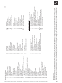
Performance curves ................................... 21
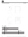
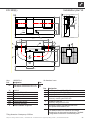
Dimensional drawings ................................ 22
LW 300 ............................................................. 22
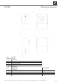
LW 300L ........................................................... 23
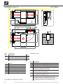
Installation plans .......................................... 24
Installation plan V1 ........................................... 24
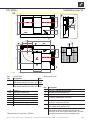
Installation plan V2 ........................................... 25
Installation plan V3 ........................................... 26
Installation plan V4 ........................................... 27
Hydraulic integration ................................... 28
...................................... 28
Keys hydraulic integration ................................ 29
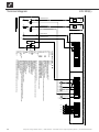
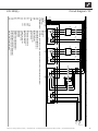
Terminal diagram ........................................ 30
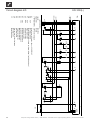
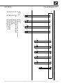
Circuit diagrams ........................................... 31
EC Declaration of Conformity .................. 35

3
Subject to change without notice | 83031300cUK – Translation of the original operating manual | ait-deutschland GmbH
1 About this operating manual
This operating manual is part of the unit.
Before working on or with the unit read the
operating manual carefully and follow it for all
activities at all times, especially the warnings and
safety instructions.
Keep the operating manual to hand at the unit and
hand over to the new owner if the unit changes
hands.
If you have any questions or anything is unclear,
ask the local partner of the manufacturer or the
factory’s customer service.
Note and follow all reference documents.
1.1 Validity
This operating manual refers solely to the unit identi-
( “Name-
plates“, page 7).
1.2 Reference documents
The following documents contain additional
information to this operating manual:
Planning & design manual, hydraulic integration
Operating manual of the heating and heat pump
controller
Brief description of the heat pump controller
Operating manual of the Comfort board 2.0
(accessories)
Log book
1.3 Symbols and markings
Symbol Meaning
Safety-relevant information.
Warning of physical injuries.
DANGER Indicates imminent danger resulting
in severe injuries or death.
WARNING Indicates a potentially dangerous
situation, which can result in severe
injuries or death.
CAUTION Indicates a potentially dangerous
situation, which can result in
moderate or minor injuries.
IMPORTANT Indicates a potentially dangerous
situation, which can result in
property damage.
Symbols in the document
Symbol Meaning
Information for the owner/operator
Requirement for action
Single step action prompt
1., 2., 3., … Numbered step within a multi-step
action prompt. Keep to the given
order.
Additional information, e.g. a tip on
making work easier, information on
standards
Reference to further information
elsewhere in the operating manual
or in another document
Listing

4
Subject to change without notice | 83031300cUK – Translation of the original operating manual | ait-deutschland GmbH
1.4 Contact
Addresses for purchasing accessories, for service
cases or for answers to questions about the unit and
this operating manual can be found on the internet and
are kept up-to-date:
Germany: www.alpha-innotec.de
EU: www.alpha-innotec.com
2 Safety
Only use the unit if it is in proper technical condition
and only use it as intended, safely and aware of the
hazards, and follow this operating manual.
2.1 Intended use
The unit is solely intended for the following functions:
Heating
Domestic hot water preparation (optional, with ac-
cessories)
Proper use includes complying with the operating
conditions ( “Technical data / scope of sup-
ply”, page 20) and the operating manual and
noting and following the reference documents.
When using the local regulations note: laws,
standards, guidelines, directives.
All other uses of the unit are not as intended.
2.2
The operating manuals supplied with the product are
intended for all users of the product.
The operation of the product via the heating and he-
at pump control and work on the product which is in-
tended for end customers / operators is suitable for all
age groups of persons who are able to understand the
activities and the resulting consequences and can car-
ry out the necessary activities.
Children and adults who are not experienced in hand-
ling the product and do not understand the necessa-
ry activities and the resulting consequences must be
instructed and, if necessary, supervised by persons
experienced in handling the product and who are re-
sponsible for safety.
Children must not play with the product.
All instructional information in this operating manual is
the work on the unit safety and correctly. Interference
injuries and damage to property.
Ensure that the personnel is familiar with the local
regulations, especially those on safe and hazard-
aware working.
only to carry out work on the electrics and
electronics.
other work on the system, e.g.
Heating installer
Plumbing installer
Refrigeration system installer (maintenance
work)
During the warranty and guarantee period, service
work and repairs may only be carried out by personnel
authorised by the manufacturer.
2.3 Personal protective equipment
There is a risk of cutting your hands on sharp edges
of the unit.
Wear cut-resistant protective gloves during trans-
port.
2.4 Residual risks
Electric shock
Components in the unit are live with life-threatening
voltage. Before opening the unit panelling:
Disconnect unit from power supply.
Protect unit against being switched back on again.
Existing earthing connections within housings or on
mounting plates must not be altered. If this should nev-
ertheless be necessary in the course of repair or as-
sembly work:
Restore earthing connections to their original con-
dition after completion of the work.

5
Subject to change without notice | 83031300cUK – Translation of the original operating manual | ait-deutschland GmbH
Injury due to moving parts
Switch device on only with air ducts and weather
Injuries and environmental damage due to
refrigerant
The unit contains harmful and environmentally
dangerous refrigerant. If refrigerant leaks from the unit:
1.
2. Thoroughly ventilate installation area.
3. Notify authorised after sales service.
2.5 Disposal
Media harmful to the environment
Improper disposal of environmentally harmful media
(refrigerant) damages the environment:
Collect media safely.
Dispose of the media in an environmentally
compatible way in accordance with the local
regulations.
2.6 Avoid damage to property
The ambient air at the heat pump installation site, as
well as the air drawn in as a heat source, must not
contain any corrosive constituents!
Constituents such as
Ammonia
Sulphur
Chlorine
Salt
can cause damage to the heat pump, which could lead
to the complete failure / destruction of the heat pump!
Decommissioning/emptying heating
If the system / heat pump is decommissioned or
to ensure that the condenser and any heat exchangers
present have been completely emptied in the event
of frost. Residual water in heat exchangers and
condensers can result in damage to components.
Empty system and condenser completely, open
vent valves.
Blast out with compressed air if necessary.
Improper action
Requirements for minimum scale and corrosion
damage in hot water heating systems:
Proper planning, design and commissioning
Closed system with regard to corrosion
Integration of an adequately dimensioned
pressure maintaining device
Use of demineralised heating water (VE water) or
water corresponding to the VDI 2035 norm
Regular servicing and maintenance
If a system is not planned, designed, started up and
operated in accordance with the given requirements,
there is a risk that the following damage and faults will
occur:
Malfunctions and the failure of components, e.g.
pumps, valves
Internal and external leaks, e.g. from heat
exchangers
Cross-section reduction and blockages in
components, e.g. heat exchanger, pipes, pumps
Material fatigue
Gas bubbles and gas cushion formation
(cavitation)
coatings, deposits, and associated noises, e.g.
Note and follow the information in this operating
manual for all work on and with the unit.
water in the heating circuit
generator and the heating components depend
decisively on the quality of the heating water.
calcium precipitates as scale. Limescale deposits
form on the heat transfer surfaces of the heating. The
cases the heat exchangers are damaged.
Fill the system with deionised heating water
(VE water) or with water corresponding to the VDI
2035 norm only (low-salt operation of the system).

6
Subject to change without notice | 83031300cUK – Translation of the original operating manual | ait-deutschland GmbH
3 Description
3.1 Delivery condition
Unit with a completely hermetically enclosed
compressor, all safety-related components for
monitoring of the cooling circuit, integrated
heating and heat pump regulator, sensors
mounted in the unit for the monitoring of hot
condensate discharge (connected to heat
pump side)
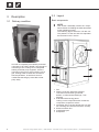
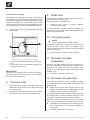
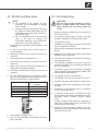
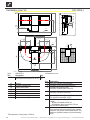
3.2 Layout
Basic components
NOTE
This section essentially names the compo-
in this operating manual.
The positions of the fan and the evaporator
are reversed in the L version.
1 Fan
2 Water connection side with hydraulic
connections and rubber grommets;
details “Dimensional drawings“, from
page 22
3 Area behind the facing panel:
cooling circuit components with condenser,
compressor, expansion valves
4 Operating side (= facing panels with cut-outs
for mounting the control unit and the screen)
5 Electrical switch box
6 Condensate pan
7 Evaporator

7
Subject to change without notice | 83031300cUK – Translation of the original operating manual | ait-deutschland GmbH
Nameplates
Nameplates are attached to the following places on
the unit when it is delivered:
outside: On the lower facing panel of the fan side
(for unit variant L: evaporator side)
inside: On the bottom of the unit by the electrical
switch box
The nameplates contain the following information at
the top:
Unit type, product number
Serial number
The nameplates also contains an overview of the most
important technical data.
3.3 Accessories
The following accessories are available for the unit
through the manufacturer’s local partner:
Installation accessories (vibration decouplers)
Air ducts (with air duct accessories)
Domestic hot water tanks
Electrical heating elements
Room control unit to control the main functions
from the living room
Comfort board 2.0
3.4 Function
Liquid refrigerant is evaporated (evaporator), the energy
for this process is environmental heat and comes from
the outside air. The gaseous refrigerant is compressed
(compressor), this causes the pressure to rise and there-
fore the temperature too. The gaseous refrigerant at a
The high temperature is hereby discharged to the
heating water and is used in the heating circuit. The
liquid refrigerant at a high pressure and high tempera-
ture is depressurised (expansion valve). The pressure
and temperature drop and the process begins again.
The heated heating water can be used for the domes-
tic hot water charging or for the building heating. The
temperatures required and use are controlled by the
heat pump controller. Reheating, drying out screed or
increasing the domestic hot water temperature can be
carried out using an electric heating element (acces-
sory), which is activated by the heat pump controller
as and when necessary.
4 Operation and care
NOTE
The unit is operated via the control unit of the
heating and heat pump controller ( Oper-
ating manual of the heating and heat pump
controller).
4.1 Energy-conscious and
environmentally-aware operation
The generally accepted requirements for an energy-
conscious and environmentally-aware operation of a
heating system also apply when using a heat pump.
The most important measures include:
No unnecessarily high domestic hot water
temperature (note and follow local regulations)
Do not open windows with gap / tilt open
(continuous ventilation), but instead open wide for
a short time (shock ventilation).
Make sure that the controller settings are correct
4.2 Care
Wipe down the outside of the unit only using a damp
cloth or cloth with mild cleaning agent (washing-up liq-
uid, neutral cleaning agent). Do not use any harsh,
abrasive, acid or chlorine-based cleaning agents.

8
Subject to change without notice | 83031300cUK – Translation of the original operating manual | ait-deutschland GmbH
5.3 Transport
Notes on safe transport
The unit is heavy ( “Technical data / scope of sup-
ply”, page 20). There is a risk of injuries or damage
to property if the unit falls or overturns.
There is a risk of cutting your hands on sharp edges
of the unit.
Wear cut-resistant protective gloves.
The hydraulic connections are not designed for me-
chanical loads.
Do not lift or transport the unit by the hydraulic
connections.
Transport the unit to the place of installation pack-
aged.
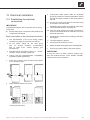
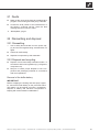
Retractable fan
In order to allow the unit to be easily transported
through tight cellar spaces and narrow doorways and/
or hallways, the fan retracts approx. 10 cm into the
body of the unit:
1 Fan in delivery condition
2 Fan pushed into the unit
IMPORTANT
Only retract the fan into the body of the unit for
transport purposes and extend it to its original posi-
tions following transport.
1. Unpack the unit.
“Unpacking”, page 11
5 Scope of supply, storage,
transport and installation
IMPORTANT
Damage to the housing and the unit components
due to heavy objects.
Do not place any objects on the unit which are
heavier than 30 kg.
IMPORTANT
Do not tilt the unit more than a maximum
of 45° (in any direction).
5.1 Scope of supply
heat pump
1 screen for control unit
4 base panels
The accompanying parts package contains:
1 outdoor temperature sensor
2 guide rods for insertable fan
1 control unit
1 holder for control unit
1 temporary cover for screen
10 countersunk screws M6x16 for base panels
2 hexagonal bolts M10x25
2 hexagonal bolts M12x40 with nuts M12
documents (manuals, ERP data and label)
nameplate stickers
Check delivery immediately after receipt for exter-
nally visible damage and completeness.
Notify supplier of any defects immediately.
5.2 Storage
Do not unpack the unit until directly before instal-
lation.
Store unit protected against
Moisture/damp
Frost
Dust and dirt

9
Subject to change without notice | 83031300cUK – Translation of the original operating manual | ait-deutschland GmbH
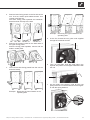
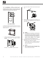
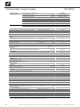
2. Remove lower facing panels on the fan side of the
unit. To do so, loosen quick-release screws. Turn
counter-clockwise 90°.
Pull lower facing panel upwards and outwards,
detach and set securely to the side.
3. Remove the screws located on the lower side of
the upper facing panel.
Slant the facing panel upwards, remove and set
aside in a safe place.
4. Then remove side facing panels from the unit too
and store safely.
Example: Removing the lower facade on the
operating side
Example: Removing the upper facade on the
operating side
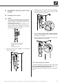
5. At the fan, thread the two guide rods supplied
through the metal tab and fan.
6. Then, on both sides, hook the guide rods in the
keyhole slot pattern of the upper metal tab inside
the unit.
7. On the inside of the device, undo all four nuts
(M12) of the fan’s connections and remove togeth-
er with the spring washers.

10
Subject to change without notice | 83031300cUK – Translation of the original operating manual | ait-deutschland GmbH
8. Push the fan in the direction of the evaporator up
to the top metal tab inside the unit.
1 top metal tab inside the unit
9. Push the screws M12 x 40 (2x) supplied through
the fan and the top metal tab and secure with nuts
M12.
10. Lower the unit at the installation location. Make
sure that the frame of the unit is in full contact with
the underlying surface and the unit is positioned
horizontally.
Undo the mounting nuts at the top metal tab and
remove the corresponding screws.
Then pull the fan out of the unit and screw tightly
back onto the unit frame (do not forget the spring
washers).
11. Remove guide rods and attach all facing panels
back onto the unit.
Transport with a pallet truck
Transport the unit with a pallet truck to the place
of installation packaged.
1 Recesses in the base for pallet truck
5.4 Installation
CAUTION
In the air outlet area the air temperature is
approx. 5 K below the ambient temperature.
Under certain climatic conditions, an ice lay-
er can therefore form in the air outlet area.
Install the heat pump such that the air blow-
er does not discharge into footpath areas
.
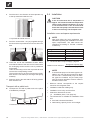
Installation room and space requirements
NOTE
Note and follow the local regulations and
standards regarding the installation room and
space requirements. The table shows the
regulations according to EN 378-1 relevant
in Germany.
Refrigerant Limit value [kg/m³]
R 134a 0,25
R 404A 0,52
R 407C 0,31
R 410A 0,44
R 448A 0,39
“Technical data / scope of supply“, page 20
Minimum room volume =
Refrigerant capacity [kg]
Limit value [kg/m³]
NOTE
If several heat pumps of the same type are in-
stalled, only one heat pump need to be taken
-
ent types are installed, only the heat pump
with the largest refrigerant volume needs to
be taken into account.
Minimum volume corresponds to the require-
ments for the refrigerant used.
Installation inside the building only.
Installation room is dry and frost-free.
Clearance dimensions are met
( “Installation plans“, from page 24).
unit:
level and horizontal foundation
load-bearing capacity for the unit’s weight

11
Subject to change without notice | 83031300cUK – Translation of the original operating manual | ait-deutschland GmbH
NOTE
The noise emissions of the heat pumps
must be taken into account in the respective
installation plans for air/water heat pumps.
The respective regional regulations must be
observed.
Unpacking
1. -
age the unit.
2. Dispose of the transport and packaging material
in an environmentally friendly way and in accord-
ance with local regulations.
Set up the unit
“Installation plans“, from page 24
1. Set up the unit so that the operating side is acces-
sible at all times.
2. Align the unit horizontally, remove the collision
protection (wooden strips on the base) and screw
on the four base panels with countersunk screws
(supplied).
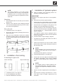
6 Installation of air ducting
Air discharge to right or left
Left air discharge Right air discharge
“Installation plans“, from page 24
Air duct installation instructions
Wall duct installation instructions
7 Installation of hydraulic system
Flush the heating circuit thoroughly before con-
necting it to the heating system.
IMPORTANT
Damage to the copper pipes due to unacceptable
loading!
Secure all connections against twisting.
Connect the unit to the heating circuit according
to the hydraulic diagram for the respective model.
Cross-sections and lengths of the pipes for the
heating circuit are adequately dimensioned.
The free pressing of the recirculating pump pro-
duces at least the minimum throughput required
for the unit type ( “Technical data / scope of
supply“, page 20).
The hydraulic system must be equipped with a
on your unit model.
“Technical data / scope of supply”, page 20
.
1.
the heat pump side.
NOTE
necessary.
Positioining of the hydraulic connections:
“Dimensional drawings“, from page 22
2. Connect the unit to the pipes of the heating circuit
via vibration decouplers. They must be installed
in order to prevent damage from vibrations to the
pipes.
NOTE
If an existing system is being replaced, the
old vibration decoupling may not be reused.
Vibration decouplers are available as acces-
sories.
3. Insert a vent at the highest point of the heating cir-
cuit.
4. Ensure that the working overpressures ( “ Tech-
nical data / scope of supply”, page 20) are not
exceeded.

12
Subject to change without notice | 83031300cUK – Translation of the original operating manual | ait-deutschland GmbH
Condensate discharge
The outlet for the heating water safety valve and the
-
ance with the respective applicable standards and reg-
ulations. Discharging the condensate and the safety
valve outlet into the sewers is only permitted via a fun-
nel waste trap, which must be accessible at all times.
Connect the hose for condendate discharge with
a water drain
1 Hose for condensate discharge in interior of
unit
2 Connection for the condensate discharge on
the outside of the unit
IMPORTANT
Guide the pre-mounted hose in the unit for conden-
sate discharge in the interior of the unit as a siphon,
as shown in the illustration.
8 Pressure relief
1. Equip the heating circuit in accordance with local
standards and directives with a safety valve and
an expansion tank.
2. -
es and non-return valves in the heating circuit.
9
The hydraulic connection of the heat pump requires a
“Technical data / scope of supply”, page 20,
“Heating circuit” section
In mono-energetic air/water systems, integrate the
10 Circulating pumps
NOTE
Do not use regulated circulating pumps.
Circulating pumps for the heating circuit and the do-
mestic hot water circuit must be multi-stage. They
must be able to deliver at least the minimum hot water
“Technical data / scope of supply“, page 20
11 Domestic hot water
preparation
Domestic hot water heating with the heat pump re-
quires an additional hot water circuit, parallel to the
heating circuit. Make sure that the heating water
heating circuit.
“Hydraulic connection” instructions
12 Domestic hot water tank
If the heat pump will be used for heating hot water,
you must integrate special hot-water tanks in the heat
pump system.
Select the hot water tank volume in such a way
that the required amount of drinking water is avail-
The heat exchanger surface of the hot water tank must
be dimensioned so that the heating capacity of the
heat pump is transferred with minimal spreading.
from. They are optimized for use with your heat pump.
Integrate the hot-water tank in the heat pump sys-
tem corresponding to the hydraulic diagram for
your system.
“Hydraulic connection” instructions

13
Subject to change without notice | 83031300cUK – Translation of the original operating manual | ait-deutschland GmbH
13 Electrical installation
13.1 Establishing the electrical
connections
IMPORTANT
Irreparable damage to the compressor due to wrong
compressor load infeed.
Basic information on the electrical connection
company may apply to electrical connections
Fit the power supply for the heat pump
with an all-pole miniature circuit-breaker
with at least 3 mm contact spacing (per
IEC 60947-2)
Note the level of the tripping current ( “Techni-
cal data / scope of supply“, page 20)
Comply with the electromagnetic compatibility
regulations (EMC regulations)
1. If the unit is closed, open the lower facing panel
on the operating side.
2. Open electrical switch box of unit.
1 Electrical switch box
3. Lead power cable, power cable for circulating
pumps and cable for external temperature sensor
through the rubber sockets on the facing panel in
the unit.
3.1. Cut out the rubber grommets on the lower facing
of the water connection side.
Positioning of the rubber grommets for cable entry:
“Dimensional drawings“, from page 22
3.2. Push the lines through the rubber grommets in-
to the unit and lead the lines inside the unit to the
electrical switch box.
4. Install electric connections according to the termi-
nal diagram.
“Terminal diagram”, page 30
5. Close electrical switch box of unit.
6. Attach the lower facing panel to the operating side.
7. Connect the power cable to the power supply.
IMPORTANT
If using the unit in 3~230V systems, please note
that the residual-current circuit breaker (RCCB)
used must be AC-DC sensitive.

14
Subject to change without notice | 83031300cUK – Translation of the original operating manual | ait-deutschland GmbH
14 Installation of the control unit
operating side of the unit are recesses (each with 4 re-
cesses) for the fastening of the control unit:
1 four upper recesses
2 four lower recesses
4 hooks are located on the back side of the control unit
and can be used to hang the control unit on the front
facade of the unit:
1. Hang the control unit’s hooks on the recesses of
the upper facade (either in the upper or lower re-
cesses.
Example: Control unit in upper recesses
2. Push the control unit down until it locks into posi-
tion.
3. Stick the heating and heat pump regulator’s con-
trol cable into the right bushing on the bottom of
the control unit.
NOTE
A connection to a computer or a network can
be installed via the left bushing on the bottom
of the control unit, thus allowing the heating
and heat pump regulator to be controlled re-
motely. One pre-condition is that a screened
network cable (category 6) be installed
through the unit when installing the unit.
Operating manual for the heating and heat pump
regulator, part 2, “Web server” section
If this network cable is available, insert the
network cable’s RJ-45 plug into the left bush-
ing of the control unit.
NOTE
The network cable can be exchanged at any
time. In order to be able to connect it, the

15
Subject to change without notice | 83031300cUK – Translation of the original operating manual | ait-deutschland GmbH
15 Installation and removal of the
screen
15.1 Installing the screen
NOTE
The screen is provided at the time of delivery
so that the control unit may be inserted in the
upper recesses of the facade facade of the
operating side of the unit.
If the control unit has been inserted in the
remove the screen’s temporary cover and
then reinsert it above the logo.
Screen at time of delivery:
1 recess for control unit
2 logo
3 temporary cover
1. First, insert the screen below, in the provided
slots on the facade.
2.
lock the screen’s snap-in lugs in place in the
slots provided on the facade.
3. Next, on the opposite side, moving upwards.
lock the screen’s snap-in lugs in place in the slots
provided on the facade.
4. Finally, press the screen’s upper snap-in lugs into
the slots provided on the facade.
15.2 Removing the screen
In order to remove the screen, the snap-in lugs must
rst be loosened by pressing one side com-
pletely toward the middle of the screen.
Thereafter, remove the snap-in lugs from the opposite
side.

16
Subject to change without notice | 83031300cUK – Translation of the original operating manual | ait-deutschland GmbH
16
16.1 Heating water quality
NOTE
For detailed information refer, among
other things, to the VDI Guidelines
2035 “Vermeidung von Schäden in
Warmwasserheizanlagen” (preventing
damage in hot water heating systems)
Required pH value: 8.2 … 10;
for aluminium materials:
pH value: 8.2 … 8.5
Fill the system with deionised heating water
(VE water) or with water corresponding to the VDI
2035 norm only (low-salt operation of the system).
Advantages of low-salt operation:
Low corrosion-promoting properties
No formation of mineral scale
Ideal for closed heating circuits
the system
If the required water quality is not achieved, con-
sult a company specialising in the treatment of
heating water.
Keep a system log for hot water heating systems
in which relevant planning data is entered (VDI
2035).
16.2
circuit
Outlet pipe of the safety valve is connected.
Ensure that the set pressure of the safety valve is
not exceeded.
1. Vent system at the respective highest point.
2. Additionally open the vent valve at the condenser
of the heat pump.
2.1. Open the lower facing panel:
For standard unit on the evaporator side.
On the fan side for unit variant L.
2.2. Open vent valve
1 Condensate pan
2 Vent valve
3 Upper edge of plate heat exchanger
3. Vent the condenser.
4. After venting, close the lower facing panel.
17 Insulate hydraulic connections
Insulate hydraulic lines in accordance with local regu-
lations.
1.
2. Perform a pressure test and check for leaks.
3. Insulate external piping on site.
4.

17
Subject to change without notice | 83031300cUK – Translation of the original operating manual | ait-deutschland GmbH
18
NOTE
The activities in this section are only
necessary for the integration of storage
tanks in series
Complete the work steps quickly, otherwise
the maximum return temperature may be
exceeded and the heat pump switches to
high-pressure fault
valve to the right to increase the
drop), turn it to the left to reduce it
System is running in heating mode (ideally in cold
condition).
1. In case of low heating curve: Set the system to
“Forced heating”.
Operating manual of the heating and heat pump
controller.
2.
3. -
4.
heating and heat pump controller.
Operating manual of the heating and heat pump
controller.
5. Turn the adjusting knob (①)
(②)
and return temperature is set as follows:
Outdoor temperature Recommended
settings
-10 °C 4 K
0 °C 5 K
10 °C 8 K
20 °C 9 K
30 °C 10 K
6. Open valves to heating circuit.
7.
pump controller.
19 Commissioning
CAUTION
The unit may only be started up if the air
ducts, weather and/or rain louvres have
been installed and the facing panels are
closed.
Relevant planning & design data of the system is
documented in full.
The relevant energy supply company has been
The system is air-free.
Installation check using the general checklist has
been completed successfully.
1. -
pletely:
available at the compressor
The system is installed and mounted according to
this operating manual
The electrical installation has been carried out
properly according to this operating manual and
the local regulations
The power supply for the heat pump is equipped
with an all-pole circuit-breaker with at least 3 mm
contact spacing (IEC 60947-2)
The tripping current is complied with
The pipe systems and components of the system
are tight
2.
for the heat pump systems.
3. In Germany: Send notice of completion for heat
pump systems and general checklist to the man-
ufacturer’s factory customer service depart-
ment.
In other countries: Send notice of completion for
heat pump systems and general checklist to the
manufacturer’s local partner.
4. Arrange for the heat pump system to be com-
missioned by the manufacturer’s authorised after
sales service for a fee.

18
Subject to change without notice | 83031300cUK – Translation of the original operating manual | ait-deutschland GmbH
20 Maintenance
NOTE
We recommend that you conclude a mainte-
nance agreement with an accredited heating
company.
20.1 Basic principles
The cooling circuit of the heat pump requires no
regular maintenance.
Local regulations– e.g. EU Regulation (EC) 517/2014
– among other things, require leak checks beforehand
and/or for a logbook to be kept for certain heat pumps.
Ensure compliance with local regulations with re-
20.2 Maintenance as required
Checking and cleaning the components of the
heating circuit, e.g. valves, expansion vessels,
Test the function of the safety valve for the heating
circuit
Always regularly control for unimpeded air in-
feed accordingly. Constrictions or even blockages
which, for example occur
when applying house insulation with polysty-
rene balls
-
tons etc.)
through foliage, snow, icing or similar weath-
er-related deposits
through vegetation (bushes, tall grass etc.)
etc.)
and which must be prevented and/or removed im-
mediately
Check regularly to ensure that the condensate
can drain out of the unit freely, without obstruc-
tion. To this end, check the condensate pan in the
unit and the evaporator regularly for dirt / block-
ages and clean as necessary.
Check evaporator and condensate pan
and clean if required
Unit is safely disconnected from the power sup-
ply and secured against being switched back on
again.
1. Remove the screen on the operating side.
2. Remove the lower and upper facing panels on the
operating side. Check the condensation pan area
for soiling.
3. Clean the condensation pan area if necessary.
For better access to the condensation pan area,
remove the lower and upper facing panels on the
water connection side if necessary.
4. Inspect the evaporator. If cleaning is required, re-
move the air ducts on the evaporator side and
clean the evaporator.
5. After cleaning, reattach the air ducts, facing pan-
els and screen to the unit. Finally, restore the
power supply.
20.3
the manufacturer’s instructions.
-
condenser thoroughly with water.
20.4 Yearly maintenance
Record the quality of the heating water analytically.
suitable measures without delay.

19
Subject to change without notice | 83031300cUK – Translation of the original operating manual | ait-deutschland GmbH
21 Faults
Read out the cause of the fault via the diagnostics
program of the heating and heat pump controller.
Contact the local partner of the manufacturer or
the factory’s customer service. Have the fault
message and unit number to hand.
“Nameplates“, page 7
22 Dismantling and disposal
22.1 Dismantling
Unit is safely disconnected from the power sup-
ply and secured against being switched back on
again.
Collect all media safely.
Separate components by their materials.
22.2 Disposal and recycling
Dispose of environmentally hazardous media in
accordance with local regulations (e.g. refrigerant,
compressor oil).
Recycle or ensure proper disposal of unit com-
ponents and packaging materials in accordance
with local regulations.
IMPORTANT
Before scrapping the heating and heat pump regula-
The battery can be pushed out using a screwdriver.
Dispose of battery and electronic components in
keeping with environmental considerations.

20
Subject to change without notice | 83031300cUK – Translation of the original operating manual | ait-deutschland GmbH
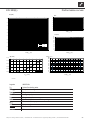
Performance data Values in brackets: (1 Compressor) LW 300(L)
Heating capacity | COP for A7/W35 acc. to EN14511 kW | COP 32,50(19,78)|3,80(4,04)
for A7/W45 acc. to EN14511 kW | COP 33,64(18,99)|3,20(3,23)
for A2/W35 acc. to EN14511 kW | COP 29,67(16,97)|3,41(3,52)
for A10/W35 acc. to EN14511 kW | COP 39,43(22,42)|4,22(4,76)
for A-7/W35 acc. to EN14511 kW | COP 24,28(13,45)|2,77(2,78)
for A-15/W65 acc. to EN14511 kW | COP – | –
for A-7/W55 acc. to EN 14511 kW | COP 24,28(13,45)|1,86(1,90)
Cooling capacity | EER for A35/W18 kW | EER – | –
for A35/W7 kW | EER – | –
Operating limits
Heating circuit return min. | Heating circuit flow max. Heating within heat source min./max. °C 20 | 45
Heating circuit return min. | Heating circuit flow max. Cooling within heat source min./max. °C – | –
Heat source heating min. I max. °C -20 | 35
Heat source cooling min. I max. °C – | –
Additional operating points … A-5/W60
Sound
Sound pressure level at 1 m distance from edge of unit inside min. | Night | max. dB(A) 48 | – | 51
Sound pressure level at 1 m distance from edge of unit outside min. | Night | max. dB(A) 40 | – | 50
Sound power level inside min. | Night | max. dB(A) 58 | – | –
Sound power level outside 1) min. | Night | max. dB(A) 55 | – | 58
Sound power level acc. to EN12102 inside | outside dB(A) 66 | 55
Tonality | Low-frequency dB(A) | • yes – no – | –
Heat source
Air flow rate at maximum external pressing | Maximum external pressure m³/h | Pa 7800 | 25
Heating circuit
Flow rate (pipe dimensioning) I Min. volume buffer tank in series I Min. volume separation buffer tank l/h | l | l 6000 | – | –
Free pressing | Pressure loss | Flow rate bar | bar | l/h 0,04 (–) | 6000
Max. allowable operating pressure bar 3
Circulation pump control range min. I max. l/h – | –
Hot gas use
Flow rate (pipe dimensioning) l/h –
Free pressing | Pressure loss | Flow rate bar | bar | l/h – | – | –
General unit data
Total weight kg 490
Weight of individual components kg | kg | kg – | – | –
Refrigerant type | Refrigerant capacity … | kg R448A | 10,0
Electrics
Voltage code | all-pole fuse protection for heat pump *)**) … | A – | –
Voltage code | all-pole fuse protection for heat pump *) + electric heating element **) … | A 3~N/PE/400V/50Hz | C32
Voltage code | Control voltage fuse protection **) … | A 1~N/PE/230V/50Hz | B10
Voltage code | Electric heating element fuse protection **) … | A – | –
HP*): effect. power consumption A7/W35 EN14511 I Electric consumption I cosφ kW | A | … 8,65 (4,87)|19,5(10,2)|0,64(0,75)
HP*): max. machine current I max. power consumption within the operating limits A | kW 28,5 | 15,6
Starting current: direct | with soft starter A | A < 101 | 38
Degree of protection
IP 20
Residual current circuit breaker if required type A
Electric heating element output 3 | 2 | 1 phase kW | kW | kW – | – | –
Circulation pump power consumption, heating circuit min. I max. W – | –
Other unit information
Safety valve heating circuit | Response pressure
included in scope of supply: • yes – no | bar – | –
Buffer tank | Volume included in scope of supply: • yes – no | l – | –
Heating circuit expansion vessel | Volume | Prepressure incl. in scope of supply: • yes – no | l | bar – | – | –
Overflow valve | Changeover valve, heating - domestic hot water integrated: • yes – no – | –
Heating circuit vibration decoupling incl. in scope of supply or integrated: • yes – no –
Controller I Heat quantity recording I Extension board incl. in scope of supply or integrated: • yes – no • | – | –
813601a
*) compressor only, **) note local regulations 1) Indoor and outdoor installation l Index: g
For indoor installation: Intake 1.5m air duct, Blow-out 1.5m air duct + air duct bend (original accessories)
Technical data / scope of supply
LW 300(L)
Page is loading ...
Page is loading ...
Page is loading ...
Page is loading ...
Page is loading ...
Page is loading ...
Page is loading ...
Page is loading ...
Page is loading ...
Page is loading ...
Page is loading ...
Page is loading ...
Page is loading ...
Page is loading ...
Page is loading ...
Page is loading ...
-
 1
1
-
 2
2
-
 3
3
-
 4
4
-
 5
5
-
 6
6
-
 7
7
-
 8
8
-
 9
9
-
 10
10
-
 11
11
-
 12
12
-
 13
13
-
 14
14
-
 15
15
-
 16
16
-
 17
17
-
 18
18
-
 19
19
-
 20
20
-
 21
21
-
 22
22
-
 23
23
-
 24
24
-
 25
25
-
 26
26
-
 27
27
-
 28
28
-
 29
29
-
 30
30
-
 31
31
-
 32
32
-
 33
33
-
 34
34
-
 35
35
-
 36
36


Alpha innotec LW 300 Owner's manual
- Category
- Heat pumps
- Type
- Owner's manual
Ask a question and I''ll find the answer in the document
Finding information in a document is now easier with AI
Related papers
-
Alpha innotec LWAR Owner's manual
-
-
Alpha innotec LW 310A Owner's manual
-
-
-
-
-
-
-
Other documents
-
Symphony 8901791100226 Datasheet
-
Alpha-InnoTec WZS 102K3M Operating instructions
-
Dimplex LA 16ASR User manual
-
Alpha-InnoTec LWCV 82R1 Operating instructions
-
Dimplex LI 20TEL User manual
-
-
-
-
EINHELL 4010390 Datasheet
-