Dettson Wire Controller Installation guide
- Category
- Split-system air conditioners
- Type
- Installation guide


This manual gives detailed description of the precautions
that should be brought to your attention during operation.
In order to ensure correct service of the wired controller
please read this manual carefully before using the unit.
For convenience of future reference, keep this manual
after reading it.
All the pictures in this manual are for explanation purpose
only. There may be slightly dierent from the wired remote
controller you purchased (depend on model). The actual
shape shall prevail.

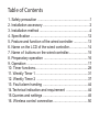
1. Safety precaution
2. Installation accessory
3. Installation method
4. Specification
5. Feature and function of the wired controller
6. Name on the LCD of the wired controller
7. Name of buttons on the wired controller
8. Preparatory operation
9. Operation
10. Timer functions
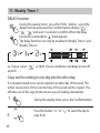
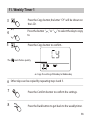
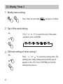
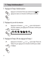
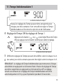
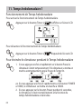
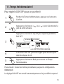
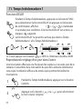
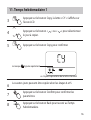
11. Weekly Timer 1
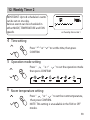
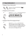
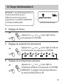
12. Weekly Timer 2
13. Fault alarm handing
14.Technical indication and requirement
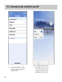
15.Queries and settings
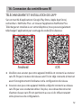
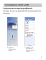
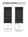
16. Wireless control connection
..........................................................1
................................................... 2
........................................................4
................................................................12
................13
.....................14
......................15
.................................................16
....................................................................17
...........................................................28
..........................................................31
.........................................................37
..................................................44
........................44
..................................................45
.......................................50
Table of Contents

1
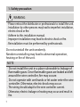
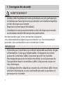
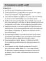
1. Safety precaution
Do not uninstall the unit randomly.
Random uninstalling may lead to abnormal operation,
heating or fire of the unit.
WARNING
Please entrust the distributor or professionals to install the unit.
Installation by other persons may lead to imperfect installation,
electric shock or re.
Adhere to this installation manual.
Imporper installation may lead to electric shock or re.
Reinstallation must be performed by professionals.
•
•
•
•
•
NOTE
•
•
Do not install the unit in a place vulnerable to leakage of
flammable gases. Once flammable gases are leaked and left
around the wire controller, fire may occure.
Do not operate with wet hands or let water enter the wire
controller. Otherwise, electric shock may occur.
The wiring should adapt to the wire controller current.
Otherwise, electric leakage or heating may occur and result in
re.
•

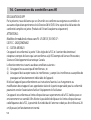
1. Safety precaution
NOTE
The specified cables shall be applied in the wiring. No external force
may be applied to the terminal. Otherwise, wire cut and heating may
occur and result in fire.
•
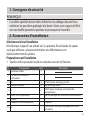
2. Installation accessory
Select the installation location
Don’t install where there is a presence of heavy oil, vapor or
sulfureted gas. Otherwise, this product would be deformed, and
it could lead to a system malfunction.
Preparation before installation
1. Please verify that all the following parts have been supply.
1
2
3
4
5
3
2
M3.9*25 (For Mounting on the Wall)
M4X25 (For Mounting on switch box)
6
7
8
3
2
No. Name Qty. Remarks
Wire controller
Installation and owner’s manual
For Mounting on the Wall
Plastic screw bars
Screws
Wall plugs
For fixing on switch box
Optional
Screws
9Screw
1
1
Battery
The connective wires group
1
1
1
M4X8 (For Mounting the connective wire group)
2

3
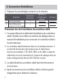
2. Installation accessory
Precaution of installing the wire controller
1. This manual provides the installation method of wired
controller. Please refer to the wiring diagram of this installation
manual to connect the wire controller with indoor unit.
2. The wired controller works in low voltage loop circuit. For to
directly contact the cable of high voltage above, like
115V,220V,380V, and don’t wire this kind of wire in the said
loop; wiring clearance between configured tubes should be at
the range of 300~500 mm or above.
3. The shielded wire of the wired controller must be grounded
firmly.
4. Upon finish the wire controller connection, do not employed
tramegger to detect the insulation.
2. Prepare the following assemblies on the site.
1
2
1
Switch box
Wiring Tube (Insulating
Sleeve and Tightening
Screw)
Qty.(embeded
into wall)
No. Name Remarks
Specication
(only for reference)
1

4
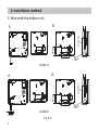
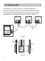
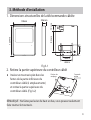
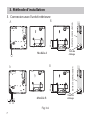
3. Installation method
Fig 3-1
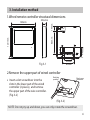
1.Wired remote controller structural dimensions
2.Remove the upper part of wired controller
Insert a slot screwdriver into the
slots in the lower part of the wired
controller (2 places), and remove
the upper part of the wire controller.
(Fig.3-2)
19mm84mm
46mm
60mm
44mm
120mm
120mm
Back cover
NOTE: Do not pry up and down, you can only rotate the screwdriver.
20.6mm
Buckling
position
(Fig.3-2)

5
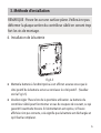
3. Installation method
Fig 3-4
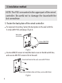
For exposed mounting, fasten the back plate on the wall with the
3 screws (M3.9*25) and plugs. (Fig.3-3)
Fig 3-3
Use two M4X25 screws to install the back cover on the 86 switch box,
and use one M3.9*25 screw to fix to the wall.
3. Fasten the back plate of the wired controller
Back plate
Screws (M3.9*25)
Screw hole fixed on the wall, useone M3.9*25mm
Screw hole installed on 86 switch box, use two M4X25mm
NOTE: The PCB is mounted in the upper part of the wired
controller. Be careful not to damage the board with the
slot screwdriver.

6
3. Installation method
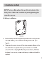
Fig 3-5
Put the battery into the designated spot and make sure the positive
side of the battery is in accordance with the positive side. (See
Fig.3-5)
Please set the correct time on the first-time operation. Battery in the
wire controller can operate when a power failure occurs which
ensure the time is kept right. When the power restores, if the time
displayed is not correct, it means the battery is dead and should be
replaced.
4. Battery installation
NOTE: Put on a at surface. Be careful not to distort the
back plate of the wire controller by overtightening the
mounting screws.

7
3. Installation method
Fig 3-6
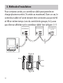
5. Wire with the indoor unit
44mm
60mm
Wiring
hole
switch box
AB
44mm
60mm
Wiring
hole
switch box
Model A
Model B
AB
HA HB
1

8
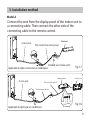
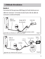
3. Installation method
Fig 3-7
Fig 3-8
Model A
Connect the wire from the display panel of the indoor unit to
a connecting cable. Then connect the other side of the
connecting cable to the remote control.
4-core wire The connective wires group
Mainboard
4-core wire
Adaptor board
Display board
The connection cable A
XYE5V/12V
White
Yellow Brown
Red
The connection cable D
Applicable to split-type air conditioner
shielded wire (some units)
Applicable to light commercial air conditioner

9
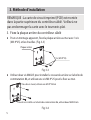
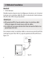
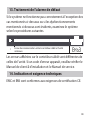
For some units, the wired controller connects to the unit HA and HB ports
through the HA and HB ports. There is no polarity between HA and HB.
See Fig. 3-9
HA HB
Indoor Unit
Wired Controller Fig.3-9
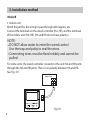
3. Installation method
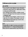
DO NOT allow water to enter the wired control.
Use the trap and putty to seal the wires.
Connecting wires must be xed reliably and cannot be
pulled.
NOTE:
Model B
1 Indoor unit
Notch the part for the wiring to pass through with nippers, etc.
Connect the terminals on the wired controller (HA ,HB), and the terminals
of the indoor unit (HA ,HB). (HA and HB do not have polarity.)

10
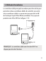
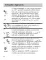
The main/secondary wired controller can be used to enable
two wired controllers to control one unit, and the wired
controllers connect to the unit HA and HB ports through the
HA and HB port on the controller. There is no polarity
between HA and HB. See Fig. 3-10
NOTE:
Wire controller with Wi-Fi function does not have
this function
.
3. Installation method
HA HB
HAHB
HAHB
Indoor Unit
Wired Controller 1
Wired Controller 2 Fig.3-10
0
1

11
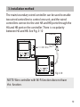
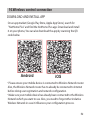
For some units, one wired controller can support multiple units (a
maximum of 16 units). In this case, the wired controller and unit need to
be connected to the HA and HB ports at the same time. In group control,
there will be no error displayed on the wired controller . See Fig. 3-11
3. Installation method
Fig 3-12
Putty
Putty
Putty
Trap
Trap
Trap
HA HB HA HB HA HB
Indoor Unit 2 Indoor Unit n
(n<=16)
Indoor Unit 1
Wired Controller 1
HAHB
Fig.3-11
0 1 2
.....

12
Fig 3-13
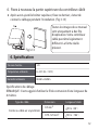
6. Reattach the upper part of the wired controller
After adjusting the upper case and then buckle the upper case;
avoid clamping the wiring during installation. (Fig 3-13)
All the pictures in this
manual are for
explanation purpose only.
Your wire controller may
be slightly dierent .The
actual shape shall prevail.
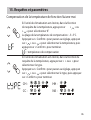
4. Specification
Wiring specications
12V
0~43℃(32~110℉)
RH40%~RH90%
Input voltage
Ambient temperature
Ambient humidity
NOTE: Suggested to use the connective wire of 6 meters length.
shielded vinyl cord or cable
0.5 mm
0.75-1.25 mm
<20 m(66’)
<50 m(164’)

13
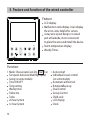
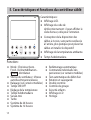
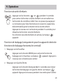
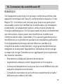
5. Feature and function of the wired controller
Feature:
Function:
LCD display.
Malfunction code display: it can display
the error code, helpful for service.
4-way wire layout design, no raised
part at backside, more convenient
to place the wires and install the device.
Room temperature display.
Weekly Timer.
Fan
Mode: Choose Auto-Cool-Dry- Heat -
Fan speed: Auto/Low/Med/High speed
Swing (on some models)
Timer ON/OFF
Temp setting
Weekly timer
Follow me
Turbo
24-hour System
12-hour System
Auto-restart
Individual louver control
(on some models)
Automatic airow test
Rotation&Back-up
Dual Control
Group Control
Child Lock
LCD display
Clock

14
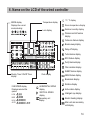
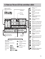
6. Name on the LCD of the wired controller
MODE display
Displays the current
mode,including:
Weekly Timer/ ON/Off Timer
display
Clock display
FAN SPEED display
Displays selected fan
speed:
LOW
MED
HIGH
AUTO
VERTICAL SWING
display
Secondary unit
display
°C / °F display
Room temperature display
Relative humidity display
HORIZONTAL SWING
display
Temperature display
Lock display
Follow me feature display
Turbo feature display
ECO feature display
GEAR feature display
SLEEP feature display
Filter reminder display
Purify feature display
Wireless control feature
display
Breeze away display
Breezeless display
Rotation display
Active clean display
Intelligent eye display
Electric heating display
Main unit and secondary
unit display
Delay off display

15
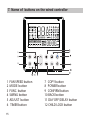
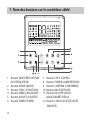
1 FAN SPEED button
2 MODE button
3 FUNC. button
4 SWING botton
5 ADJUST button
6 TIMER button
7 COPY button
8 POWER button
9 CONFIRM button
10 BACK botton
11 DAY OFF/DELAY button
12 CHILD LOCK button
7. Name of buttons on the wired controller

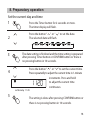
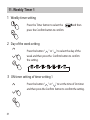
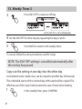
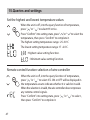
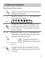
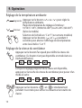
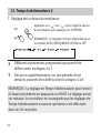
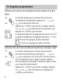
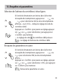
Press the button “ ” or “ ” to set the current time.
Press repeatedly to adjust the current time in 1-minute
increments. Press and hold
to adjust the current time
continuous.
16
5
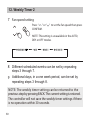
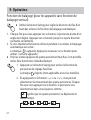
Press the Timer button for 2 seconds or more.
The timer display will ash.
1
2
3
4
The date setting is nished and the time setting is prepared
after pressing Timer button or CONFIRM button or there is
no pressing button in 10 seconds.
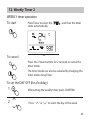
The setting is done after pressing CONFIRM button or
there is no pressing button in 10 seconds.
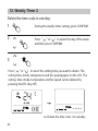
Set the current day and time
ex.Monday 11:20
Press the button “ ” or “ ” to set the date.
The selected date will ash.
8. Preparatory operation

17
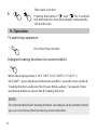
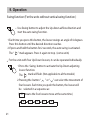
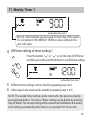
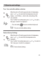
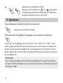
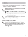
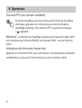
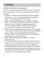
9. Operation
To start/stop operation
Press the Power button.
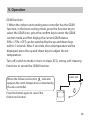
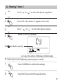
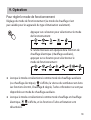
6Time scale selection
Pressing the buttons “ ” and “ ” for 2 seconds
will alternate the clock time display between the
12h & 24h scale.
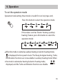
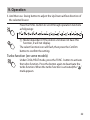
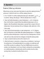
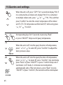
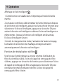
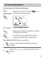
NOTE:
For some models, the 8° heating function can only be set by remote control,
you can not choose this function by wired controller.
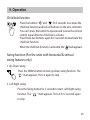
8 degree heating function (on some models)
When the heating mode is 10°C (50°F )/16°C (60°F)/17°C (62°F ) /
20°C( 68°F) , press the down button twice within 1 second to turn on the 8
° heating function, and press the Power, Mode, adjust , Fan speed, Timer,
and Swing button to cancel the 8° heating function.
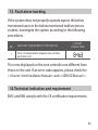
Page is loading ...
Page is loading ...
Page is loading ...
Page is loading ...
Page is loading ...
Page is loading ...
Page is loading ...
Page is loading ...
Page is loading ...
Page is loading ...
Page is loading ...
Page is loading ...
Page is loading ...
Page is loading ...
Page is loading ...
Page is loading ...
Page is loading ...
Page is loading ...
Page is loading ...
Page is loading ...
Page is loading ...
Page is loading ...
Page is loading ...
Page is loading ...
Page is loading ...
Page is loading ...
Page is loading ...
Page is loading ...
Page is loading ...
Page is loading ...
Page is loading ...
Page is loading ...
Page is loading ...
Page is loading ...
Page is loading ...
Page is loading ...
Page is loading ...
Page is loading ...
Page is loading ...
Page is loading ...
Page is loading ...
Page is loading ...
Page is loading ...
Page is loading ...
Page is loading ...
Page is loading ...
Page is loading ...
Page is loading ...
Page is loading ...
Page is loading ...
Page is loading ...
Page is loading ...
Page is loading ...
Page is loading ...
Page is loading ...
Page is loading ...
Page is loading ...
Page is loading ...
Page is loading ...
Page is loading ...
Page is loading ...
Page is loading ...
Page is loading ...
Page is loading ...
Page is loading ...
Page is loading ...
Page is loading ...
Page is loading ...
Page is loading ...
Page is loading ...
Page is loading ...
Page is loading ...
Page is loading ...
Page is loading ...
Page is loading ...
Page is loading ...
Page is loading ...
Page is loading ...
Page is loading ...
Page is loading ...
Page is loading ...
Page is loading ...
Page is loading ...
Page is loading ...
Page is loading ...
Page is loading ...
Page is loading ...
Page is loading ...
Page is loading ...
Page is loading ...
Page is loading ...
Page is loading ...
Page is loading ...
Page is loading ...
Page is loading ...
Page is loading ...
Page is loading ...
Page is loading ...
Page is loading ...
Page is loading ...
Page is loading ...
Page is loading ...
Page is loading ...
Page is loading ...
Page is loading ...
Page is loading ...
Page is loading ...
Page is loading ...
-
 1
1
-
 2
2
-
 3
3
-
 4
4
-
 5
5
-
 6
6
-
 7
7
-
 8
8
-
 9
9
-
 10
10
-
 11
11
-
 12
12
-
 13
13
-
 14
14
-
 15
15
-
 16
16
-
 17
17
-
 18
18
-
 19
19
-
 20
20
-
 21
21
-
 22
22
-
 23
23
-
 24
24
-
 25
25
-
 26
26
-
 27
27
-
 28
28
-
 29
29
-
 30
30
-
 31
31
-
 32
32
-
 33
33
-
 34
34
-
 35
35
-
 36
36
-
 37
37
-
 38
38
-
 39
39
-
 40
40
-
 41
41
-
 42
42
-
 43
43
-
 44
44
-
 45
45
-
 46
46
-
 47
47
-
 48
48
-
 49
49
-
 50
50
-
 51
51
-
 52
52
-
 53
53
-
 54
54
-
 55
55
-
 56
56
-
 57
57
-
 58
58
-
 59
59
-
 60
60
-
 61
61
-
 62
62
-
 63
63
-
 64
64
-
 65
65
-
 66
66
-
 67
67
-
 68
68
-
 69
69
-
 70
70
-
 71
71
-
 72
72
-
 73
73
-
 74
74
-
 75
75
-
 76
76
-
 77
77
-
 78
78
-
 79
79
-
 80
80
-
 81
81
-
 82
82
-
 83
83
-
 84
84
-
 85
85
-
 86
86
-
 87
87
-
 88
88
-
 89
89
-
 90
90
-
 91
91
-
 92
92
-
 93
93
-
 94
94
-
 95
95
-
 96
96
-
 97
97
-
 98
98
-
 99
99
-
 100
100
-
 101
101
-
 102
102
-
 103
103
-
 104
104
-
 105
105
-
 106
106
-
 107
107
-
 108
108
-
 109
109
-
 110
110
-
 111
111
-
 112
112
-
 113
113
-
 114
114
-
 115
115
-
 116
116
-
 117
117
-
 118
118
-
 119
119
-
 120
120
-
 121
121
-
 122
122
-
 123
123
-
 124
124
-
 125
125
-
 126
126
-
 127
127
-
 128
128


Dettson Wire Controller Installation guide
- Category
- Split-system air conditioners
- Type
- Installation guide
Ask a question and I''ll find the answer in the document
Finding information in a document is now easier with AI