Page is loading ...

ITM. / ART. 1319073
ASSEMBLY INSTRUCTIONS
* Specifications may vary from this image and are subject to change without notice.
EN
For gravity-assisted stretching and decompression
FitSpine FX-2
™
Inversion Table
with Comfort Cushion
FASTER, BETTER
RESULTS WITH
TEETER SUPPORT
& COACHING
ASSEMBLE FASTER
Free BILT app puts easy 3-D
instructions at your fingertips.
Search ‘Teeter FX-2’ in BILT to
get started.
Scan or
Find BILT
in App Store
EASY ACCESS TO VIDEO
Watch the Getting Started DVD
or access videos online for easy
assembly guidance, how-to’s
and classes.
Scan or
Go to
teeter.com/videos
FREE EXERCISE GUIDE
Register your warranty and gain
access to our 30-Day Back Pain
Relief Guide.
Scan or
Go to
teeter.com/warranty
REACH YOUR GOALS
Use the free Teeter app to
access guided sessions,
product support, and more!

Owner’s Manual (attached to the equipment)
Important Safety Instructions .........................1
User Settings .........................................2
Prepare to Invert .................................. 3 – 4
Inverting .......................................... 4 – 5
Storage & Maintenance............................... 5
Get the Most Out of Your Teeter......................6
Assembly Instructions
Important Safety Instructions .........................1
Items for Assembly ...................................2
A Guide to Your Inversion Table....................... 3
Safety Warning Labels & Product Specifications.....4
Assembly Steps ................................... 5 – 13
Before Inverting ..................................... 14
Warranty Terms & Registration ...................... 15
Congratulations on your purchase of a Teeter FitSpine FX-2™ Inversion Table!
For the best experience, it is critical that you follow the assembly instructions,
and read and fully understand the Owner’s Manual attached to the equipment
before inverting. Teeter Decompression Devices are multiple user, reusable
medical devices for home use, intended to provide traction to the spine while
stretching the para-spinal muscle and soft tissues. The devices provide
non-powered traction and are meant for use by adults.
Teeter inversion tables are FDA-Registered as 510(k) medical devices.
Indicated for:
If you have any questions concerning assembly or if any parts are missing,
DO NOT RETURN THE ITEM TO THE STORE OR CONTACT THE RETAILER.
Our dedicated product service experts can help! Contact Teeter Customer Service
at 800-847-0143, or via online forms or Live Chat at teeter.com.
Trust Teeter for unmatched quality and performance, backed by our
industry-leading warranty coverage. To register your product warranty,
go to teeter.com/warranty
• Herniated disc
• Spinal curvature due to tight muscles
• Sciatica
• Muscle spasm
• Facet syndrome
• Back pain
• Muscle tension
• Degenerative disc disease
• Spinal degenerative joint disease
• Spinal stenosis
WELCOME TO THE TEETER FAMILY
We’ve Got Your Back!
YEAR
5
W
A
R
R
A
N
T
Y
FULL
TABLE OF CONTENTS
I created Teeter so people
could live healthier and
more active lives.

SAVE THESE INSTRUCTIONS
WARNING
!
IMPORTANT SAFETY INSTRUCTIONS
READ ALL INSTRUCTIONS BEFORE USING THE INVERSION TABLE
BEFORE YOU BEGIN: Review all steps before beginning assembly and read all precautions before using the inversion table.
Carefully adhere to the Assembly Instructions and Owner’s Manual to help ensure safety and product integrity.
FAILURE TO FOLLOW INSTRUCTIONS AND WARNINGS COULD RESULT IN SERIOUS INJURY OR DEATH.
To reduce the risk of injury:
• Read and understand all the instructions, review all other accompanying documents, and inspect the equipment before using the
inversion table. It is your responsibility to familiarize yourself with the proper use of this equipment and the inherent risks of inversion
if these instructions are not followed, such as falling on your head or neck, pinching, entrapment, equipment failure, or aggravating a
pre-existing medical condition. It is the responsibility of the owner to ensure that all users of the product are fully informed about the
proper use of the equipment and all safety precautions.
• DO NOT use until approved by a licensed physician. Inversion is contraindicated in any medical or health condition that may be
made more severe by an elevation of blood pressure, intracranial pressure or mechanical stress of the inverted position, or that may
impact your ability to operate the equipment. This may include injury or illness, but also the side effects of any drug or supplement
(prescribed or over-the-counter). Specific conditions may include, but not be limited to:
· Any condition, neurological or otherwise, which results in unexplained tingling, weakness or neuropathy, seizure, sleep disorder,
lightheadedness, dizziness, disorientation, or fatigue, or impacts strength, mobility, alertness, or cognitive ability;
· Any brain condition, such as trauma, history of intracranial bleed, history or risk of TIA or stroke, or severe headaches;
· Any condition of the heart or circulatory system, such as high blood pressure, hypertension, increased risk of stroke, or use of
anticoagulants (including high doses of aspirin);
· Any bone, skeletal or spinal cord condition or injury, such as significant spinal curvature, acutely swollen joints, osteoporosis,
fractures, dislocations, medullary pins or surgically implanted orthopedic supports;
· Any eye, ear, nasal or balance condition, such as trauma, history of retinal detachment, glaucoma, optic hypertension, chronic
sinusitis, middle or inner ear disease, motion sickness, or vertigo;
· Any digestive or internal condition, such as severe acid reflux, hiatal or other hernia, gallbladder or kidney disease;
· Any condition for which exercise is specifically directed, limited or prohibited by a physician, such as pregnancy, obesity,
or recent surgery.
• ALWAYS be certain the Ankle Lock System is properly adjusted and fully engaged, and that your ankles are secure before using the
equipment. HEAR, FEEL, SEE and TEST that the Ankle Lock System is snug, close-fitting and secure EVERY TIME you use
the equipment.
• ALWAYS wear securely tied lace-up shoes with a flat sole, such as a normal tennis-style shoe.
• DO NOT wear any footwear that could interfere with securing the Ankle Lock System, such as shoes with thick soles, boots, high-tops
or any shoe that extends above the anklebone.
• DO NOT use the inversion table until it is adjusted properly for your height and body weight. Improper settings can cause rapid
inversion or make returning upright difficult. New users, and users who are physically or mentally compromised, will require the
assistance of a spotter. Make sure the equipment is set to your unique user settings prior to each use.
• DO NOT sit up or raise head to return upright. Instead, bend knees and slide your body to the foot-end of the inversion table to
change weight distribution. If locked out in full inversion, follow the instructions for releasing from the locked position before
returning upright.
• DO NOT continue using the equipment if you feel pain or become light-headed or dizzy while inverting. Immediately return to the
upright position for recovery and eventual dismount.
• DO NOT use if you are over 198 cm / 6 ft 6 in or over 136 kg (300 lb). Structural failure could occur or head / neck may impact the floor
during inversion.
• DO NOT allow children to use this machine. Keep children, bystanders, and pets away from machine while in use. The inversion table
is not intended for use by persons with reduced physical, sensory or mental capabilities, unless they are given supervision and
instruction concerning use of the machine by a person responsible for their safety.
• DO NOT store the inversion table upright if children are present. Fold and lay the table on the floor. DO NOT store outdoors.
• DO NOT use aggressive movements, or use weights, elastic bands, any other exercise or stretching device or non-Teeter®
attachments while on the inversion table. Use the inversion table only for its intended use as described in this manual.
• DO NOT drop or insert any object into any opening. Keep body parts, hair, loose clothing and jewelry clear of all moving parts.
• DO NOT use in any commercial, rental or institutional setting. This product is intended for indoor, home-use only.
• DO NOT operate equipment while under the influence of drugs, alcohol, or medication that may cause drowsiness or disorientation.
• ALWAYS inspect the equipment prior to use. Make sure all fasteners are secure.
• ALWAYS replace defective components immediately and / or keep the equipment out of use until repair.
• ALWAYS position equipment on a level surface and away from water or ledges that could lead to accidental immersion or falls.
• Refer to additional warning notices posted on the equipment. If a product label or Owner’s Manual should become lost, damaged or
illegible, contact Customer Service at 800-847-0143 for replacement.
1

Stretch-and-Grip™ A-Frame
Base Assembly
with pre-assembled Angle Tether
E61100
F51007
FitSpine™ Table Bed Assembly
Use with Table Bed Hardware Kit (HK1010)
EX1300
E61500
F51064B
ITEM NO. ITEM NAME
Stretch-and-Grip™ A-Frame Base Assembly
E61100 A-Frame
F51007 Angle Tether pre-assembled to A-Frame
Handle Assembly
E61500 Stretch Assist™ Handles (2)
HK1008 Handle Assembly Hardware Kit
F50071 Allen Head Bolt (6)
Roller Hinge Assembly
F51064B Roller Hinges (2)
FitSpine™ Table Bed Assembly
EX1300 FitSpine™ Table Bed
HK1010 FitSpine™ Table Bed Hardware Kit
EP1127 Bolt (2), H13009 Nut (2), EP1128 Washer (2)
Handle Assembly
Use with Handle Assembly
Hardware Kit (HK1008)
Roller Hinge Assembly
Tools Provided for Assembly
IA1149
5mm Allen Wrench
EZ-Reach™
Ankle Lock System
EX1630
F51088
Open-Ended Wrench
ITEM NO. ITEM NAME
Main Shaft Assembly
EX1630 with EZ-Reach™ Ankle Lock System
Tools Provided for Assembly
IA1149 5mm Allen Wrench (1)
EP1128A 6mm Allen Wrench (1)
F51088 Open-Ended Wrench (1)
Product Support
LI2100 Owner’s Manual pre-assembled to A-Frame
Included Accessories (Optional)
EX1350 Lumbar Bridge
EX1450 Comfort Cushion
EX1397 Attachment Nodes
Product Support
LI2100
Owner’s Manual
pre-assembled to A-Frame
REV.
DESCRIPTION REV.DATE
APP.DATE
APPROVED
STL-20150420-說明書 2015/4/20
C
A
B
D
E
6
5
4
3
29
8
7
C
A
B
D
E
F
G
H
1
23456789
F
G
H
EP1128A
6mm Allen Wrench
Main Shaft Assembly
2
ITEMS FOR ASSEMBLY
Parts are not shown to scale.
Lumbar Bridge
EX1350 EX1397
REVISIONS
ENGR
DATE
REV
SHT
ZONE
DESCRIPTION
NMS
10/18/2017
A
1
8D A1: RELEASE FOR PATENT
PARTS LIST
ITEM
QTY NET DIMENSIONS/DESCRIPTION
NOTE
MATERIAL
SHT
REVISION STATUS
SHT 1
REV
A
8
A
1234567
D
C
B
C
A
D
B
5 3 16 248 7
8
A
1234567
D
C
B
C
A
D
B
5 3 16 248 7
nodes
SHEET 1 OF 1
REV
PROJECT:
DRAWN
UNLESS OTHERWISE NOTED
SURFACE ROUGHNESS PER ANSI B46.1
DIMENSIONING PER ASME Y14.5-2009
WELD SYMBOLS PER AWS A2.4
FINISH:
UOS 63RMS ON
MACHINED
SURFACES OR
AS PROCURED
.X
.XX
.XXX
ANGLE
EXPECTATIONS PROPRIETARY
THE INFORMATION CONTAINED HEREIN
IS PROPRIETARY TO EXPECTATIONS AND
SHALL NOT BE REPRODUCED IN WHOLE
OR IN PART OR USED FOR ANY PURPOSE
EXCEPT WHEN SUCH USER POSSESSES
DIRECT WRITTEN AUTHORIZATION
FROM EXPECTATIONS LLC
SCALE: FULL
SIZE:
D
A
TOLERANCES
UNLESS NOTED
=
.1
=
.03
=
.005
=
1
NICK SOLLER
FILLET RADII: .005-.010
CORNER BREAK: .005-.010
ALL DIMENSIONS IN INCHES
EXPECTATIONS LLC
PUYALLUP, WA 98391
DRAWING
PROJECT NAME HERE
REVISIONS
ENGR DATE
REV
SHT
ZONE
DESCRIPTION
NMS
10/18/2017
A
1
8D A1: RELEASE FOR PATENT
PARTS LIST
ITEM
QTY
NET DIMENSIONS/DESCRIPTION NOTE
MATERIAL
SHT
REVISION STATUS
SHT 1
REV
A
8
A
1234567
D
C
B
C
A
D
B
5 3 16 248 7
8
A
1234567
D
C
B
C
A
D
B
5 3 16 248 7
lumbar bridge
SHEET 1 OF 1
REV
PROJECT:
DRAWN
UNLESS OTHERWISE NOTED
SURFACE ROUGHNESS PER ANSI B46.1
DIMENSIONING PER ASME Y14.5-2009
WELD SYMBOLS PER AWS A2.4
FINISH:
UOS 63RMS ON
MACHINED
SURFACES OR
AS PROCURED
.X
.XX
.XXX
ANGLE
EXPECTATIONS PROPRIETARY
THE INFORMATION CONTAINED HEREIN
IS PROPRIETARY TO EXPECTATIONS AND
SHALL NOT BE REPRODUCED IN WHOLE
OR IN PART OR USED FOR ANY PURPOSE
EXCEPT WHEN SUCH USER POSSESSES
DIRECT WRITTEN AUTHORIZATION
FROM EXPECTATIONS LLC
SCALE: FULL
SIZE:
D
A
TOLERANCES
UNLESS NOTED
=
.1
=
.03
=
.005
=
1
NICK SOLLER
FILLET RADII: .005-.010
CORNER BREAK: .005-.010
ALL DIMENSIONS IN INCHES
EXPECTATIONS LLC
PUYALLUP, WA 98391
DRAWING
PROJECT NAME HERE
Included Accessories
Attachment NodesComfort Cushion
EX1450
F50071
EP1127 H13009 EP1128
REVISIONS
ENGR
DATE
REV
SHT
ZONE
DESCRIPTION
NMS
10/18/2017
A
1
8D A1: RELEASE FOR PATENT
PARTS LIST
ITEM
QTY NET DIMENSIONS/DESCRIPTION
NOTE
MATERIAL
SHT
REVISION STATUS
SHT 1
REV
A
8
A
1234567
D
C
B
C
A
D
B
5 3 16 248 7
8
A
1234567
D
C
B
C
A
D
B
5 3 16 248 7
nodes
SHEET 1 OF 1
REV
PROJECT:
DRAWN
UNLESS OTHERWISE NOTED
SURFACE ROUGHNESS PER ANSI B46.1
DIMENSIONING PER ASME Y14.5-2009
WELD SYMBOLS PER AWS A2.4
FINISH:
UOS 63RMS ON
MACHINED
SURFACES OR
AS PROCURED
.X
.XX
.XXX
ANGLE
EXPECTATIONS PROPRIETARY
THE INFORMATION CONTAINED HEREIN
IS PROPRIETARY TO EXPECTATIONS AND
SHALL NOT BE REPRODUCED IN WHOLE
OR IN PART OR USED FOR ANY PURPOSE
EXCEPT WHEN SUCH USER POSSESSES
DIRECT WRITTEN AUTHORIZATION
FROM EXPECTATIONS LLC
SCALE: FULL
SIZE:
D
A
TOLERANCES
UNLESS NOTED
=
.1
=
.03
=
.005
=
1
NICK SOLLER
FILLET RADII: .005-.010
CORNER BREAK: .005-.010
ALL DIMENSIONS IN INCHES
EXPECTATIONS LLC
PUYALLUP, WA 98391
DRAWING
PROJECT NAME HERE
REVISIONS
ENGR
DATE
REV
SHT
ZONE
DESCRIPTION
NMS
10/18/2017
A
1
8D A1: RELEASE FOR PATENT
PARTS LIST
ITEM
QTY NET DIMENSIONS/DESCRIPTION
NOTE
MATERIAL
SHT
REVISION STATUS
SHT 1
REV
A
8
A
1234567
D
C
B
C
A
D
B
5 3 16 248 7
8
A
1234567
D
C
B
C
A
D
B
5 3 16 248 7
nodes
SHEET 1 OF 1
REV
PROJECT:
DRAWN
UNLESS OTHERWISE NOTED
SURFACE ROUGHNESS PER ANSI B46.1
DIMENSIONING PER ASME Y14.5-2009
WELD SYMBOLS PER AWS A2.4
FINISH:
UOS 63RMS ON
MACHINED
SURFACES OR
AS PROCURED
.X
.XX
.XXX
ANGLE
EXPECTATIONS PROPRIETARY
THE INFORMATION CONTAINED HEREIN
IS PROPRIETARY TO EXPECTATIONS AND
SHALL NOT BE REPRODUCED IN WHOLE
OR IN PART OR USED FOR ANY PURPOSE
EXCEPT WHEN SUCH USER POSSESSES
DIRECT WRITTEN AUTHORIZATION
FROM EXPECTATIONS LLC
SCALE: FULL
SIZE:
D
A
TOLERANCES
UNLESS NOTED
=
.1
=
.03
=
.005
=
1
NICK SOLLER
FILLET RADII: .005-.010
CORNER BREAK: .005-.010
ALL DIMENSIONS IN INCHES
EXPECTATIONS LLC
PUYALLUP, WA 98391
DRAWING
PROJECT NAME HERE

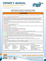
Located on
back of table
bed.
Height-Selector
Locking Pin
Spreader Arms
Handles
A-Frame
Pivot Pins
Hinge Plates
Self-Locking
Hooks
3-Hole Roller
Hinges
Main Shaft
Crossbar
Table Bed
Upper Support Arms
3
Before reading further, study the drawing below to familiarize yourself with the
important components of your Teeter Inversion Table.
A GUIDE TO YOUR INVERSION TABLE
Angle Tether
Ankle Lock System
Ankle Comfort Dial Non-Skid Stability Feet

73.1 cm / 28.8 in
153.6 cm / 60.5 in
147.3 cm / 58 in
SERIOUS INJURY OR DEATH MAY OCCUR IF PRECAUTION IS NOT TAKEN. To reduce this risk:
• READ and understand instructions in Owner’s Manual and on equipment before attempting to use.
•
ALWAYS properly set Main Shaft height. Too short can cause rapid inversion and difficultly returning upright.
• TIPPING HAZARD: Ensure that Spreader Arms are fully engaged in the locked position. To store upright, leave
A-Frame open enough to remain stable or secure to wall. If children are present, store flat on floor, not upright.
• DO NOT allow children to use this machine. Keep children, bystanders and pets away when in use.
• Keep body parts, hair, loose clothing and jewelry clear of all moving parts.
• Height / Weight Capacity: 142 - 198 cm / 4 ft 8 in - 6 ft 6 in; 136 kg / 300 lb. For consumer, indoor Home-Use Only.
4
Important: Please review all labels and supporting materials before using your inversion table.
This drawing indicates the locations of the warning labels found on your product. If a label is missing,
illegible or is removed, contact Teeter Customer Service to request a complimentary replacement label.
Note: Image and labels below not shown at actual size.
SAFETY WARNING LABELS
& PRODUCT SPECIFICATIONS
Assembled Non-Use Dimensions: 147.3 x 73.1 x 153.6 cm / 58 x 28.8 x 60.5 in
Maximum In-Use Dimensions: 205.7 x 73.1 x 219.7 cm / 81 x 28.8 x 86.5 in
Storage Dimensions: 50.8 x 73.1 x 167.6 cm / 20 x 28.8 x 66 in
Weight (approx.): 28.4 kg / 62.6 lb

5
FIGURE 4 ASSEMBLE AFRAME & HANDLES
STEP 1
Unpack and Prepare Your Workspace
• If possible, assemble the equipment at or near the space in which you intend to use it to avoid moving it later.
• Unpack all parts and support materials. Set aside packing materials and clear your work area.
• Locate the Hardware Kits packaged with the manuals. They are labeled to correspond with the assembly process.
LET’S GET STARTED
Figure 1: On a level surface, position the A-Frame so
that it is standing upright and the Stability Feet are
on the ground.
Gently push down on the Spreader Arms to ensure they
are fully open and in the “locked” position.
Look for temporary circular assembly assistance labels
on the A-Frame. RIGHT, LEFT, FRONT, and REAR indicate
your position while using the equipment, not facing it.
These labels can be removed easily upon completion
of assembly.
Locate the Handle Assembly Hardware Kit (HK1008).
Figure 2: Determine the left or right handles, marked with
an embossed L / R on the inside of the black plastic part
of each handle.
Align the black plastic part of the corresponding handle
(left / right) over the outside edge of the Hinge Plate on
the A-Frame.
Figure 3: Insert and loosely hand-tighten three of
the Allen Head Screws through the Hinge Plate into
the handle.
Repeat with other handle. Tighten all fasteners with
the 5mm Allen Wrench provided, being careful not to
over-tighten.
A - Spreader Arms B - Crossbar
LEFT
RIGHT
A
B
REAR
FRONT
UNLOCKED
Figure 1
Figure 2
Figure 3
3x Allen Head Bolts F50071 per side

6
FIGURE 4
STEP 2 ASSEMBLE TABLE BED
Locate the Table Bed Assembly Hardware Kit (HK1010).
Figure 4: Place the Table Bed face down on the floor and
push down on the Support Beam, so the two holes align
evenly with the holes at the base of the Upper Support
Arms. You may have to exert extra pressure to ensure
that the Support Beam slides over the rubber spacers.
Figure 4
Figure 5: Insert the two Bolts into the open holes.
Thread a Washer and Nut onto each Bolt and
hand-tighten.
Using the 6mm Allen Wrench to steady the bolts,
tighten the Nuts onto the Bolts with the 10/13mm
Open-Ended Wrench.
Figure 5
Washers
Bolts
Nuts
Support Beam Upper Support Arms

UNLOCKED
Bracket Pin Cam Lock
Pivot Pin Bracket
C
B
A
OPEN / UNLOCKED
LOCKED
NEVER disassemble the Roller Hinge Pivot Pin.
ALWAYS insert the 3-Hole Roller Hinge (with the Pivot Pin on top
and facing out) in the same direction as the arrow label located
inside of the Cam Lock for proper assembly.
WARNING
!
Figure 7: For ease of assembly, rest the Table Bed against
the Crossbar at the front of the A-Frame.
Figure 7a: On one side of the Table Bed, lift and hold the
Cam Lock up all the way to unlock.
In your other hand, hold one Roller Hinge near the Pivot
Pin. With the Pivot Pin facing out (away from the Table
Bed), slide the bottom of the Roller Hinge between the
Cam Lock and the Bracket in the same direction as the
arrow label located inside of the Cam Lock.
TIP: Make sure that the Cam Lock is completely open
when inserting the Roller Hinge, otherwise assembly will
be more difficult.
Figure 6: Familiarize yourself with the 3-Hole Roller Hinge
and Cam Lock terms.
FIGURE 4
STEP 3 ASSEMBLE ROLLER HINGES
TO TABLE BED
7
Figure 8: Engage one of the holes in the Roller Hinge
over the Bracket Pin. Push down on the Cam Lock to lock
it and secure the Roller Hinge.
Repeat on other side. Make sure the Roller Hinges are in
the same hole setting on both sides.
Figure 9: This figure shows the Roller Hinge installed
correctly, with the Bracket Pin engaged in Setting C.
NOTE: Refer to the Owner’s Manual for an explanation
of the hole settings. If you are unsure, use Setting C
to start.
Figure 7a
Figure 7
Figure 6
CLOSED / LOCKED
Figure 8
Figure 9

Failure of the Self-Locking Hooks to close over both Roller Hinge
Pivot Pins is an indication of improper assembly and if not corrected
could result in serious injury or death!
WARNING
!
Figure 12: Rotate the Table Bed so that it is facing up.
Ensure that it rotates smoothly. See also Image A on Page
10 to ensure correct assembly.
TOP VIEW
INSIDE VIEW
FIGURE 4
STEP 4 ASSEMBLE TABLE BED TO AFRAME
8
Figure 11: Lower each Roller Hinge Pivot Pin into the
A-Frame hinge plates, one side at a time. The Self-Locking
Hooks will open to allow the Pivot Pin into the Hinge Plate
slot, then automatically snap closed over the Pivot Pin.
TIP: You may need to push outward on the Hinge Plate in
order for the second Pivot Pin to lock in place.
Figure 11a & 11b: Make sure that each Pivot Pin is seated at
the base of the slot in the Hinge Plates, and that the Self-
Locking Hooks have closed over both Pivot Pins.
Figure 10: Face the front of the A-Frame where the
Crossbar is located. Grasp both Roller Hinges, right above
the Cam Lock, and lift the Table Bed. Allow the top of the
Table Bed to rotate toward the floor, so that the back of the
Table Bed is now facing you and the top of the Table Bed is
in front of the Crossbar.
Figure 10
Figure 11
Figure 12
Figure 11b
Figure 11a

FIGURE 4
STEP 5 ASSEMBLE MAIN SHAFT TO TABLE BED
9
Figure 15: Test the inversion table by hand for
smooth and steady rotation and ensure that all
fasteners are secure.
Figure 13: Stand on the LEFT side of the A-Frame,
holding the Main Shaft with the height markings
facing up. Begin to slide the end of the Main Shaft
into the Main Shaft Housing at the base of the
Table Bed.
Figure 13a: With your right hand, pull out the
Height-Selector Locking Pin and slide the Main
Shaft in further. Release in the desired height
setting. Refer to the Owner’s Manual for more
information on selecting your height setting.
Figure 14: The Main Shaft MUST REST against the
Crossbar of the A-Frame.
IMPORTANT: The Crossbar prevents the Table Bed
from rotating forward when the user steps on the
Ankle Comfort Dial. If the Main Shaft does not rest
on the Crossbar as shown here, then the Table Bed
has been assembled backwards onto the A-Frame.
This must be corrected before use.
Figure 13
Figure 14
REVISIONS
ENGR
DATE
REV
SHT
ZONE
DESCRIPTION
NMS
10/18/2017
A
1
8D
A1: RELEASE FOR PATENT
PARTS LIST
ITEM
QTY
NET DIMENSIONS/DESCRIPTION
NOTE
MATERIAL
SHT
REVISION STATUS
SHT
1
REV
A
8
A
1234567
D
C
B
C
A
D
B
5 3 16 248 7
8
A
1234567
D
C
B
C
A
D
B
5 3 16 248 7
figure 18
SHEET 1 OF 1
REV
PROJECT:
DRAWN
UNLESS OTHERWISE NOTED
SURFACE ROUGHNESS PER ANSI B46.1
DIMENSIONING PER ASME Y14.5-2009
WELD SYMBOLS PER AWS A2.4
FINISH:
UOS 63RMS ON
MACHINED
SURFACES OR
AS PROCURED
.X
.XX
.XXX
ANGLE
EXPECTATIONS PROPRIETARY
THE INFORMATION CONTAINED HEREIN
IS PROPRIETARY TO EXPECTATIONS AND
SHALL NOT BE REPRODUCED IN WHOLE
OR IN PART OR USED FOR ANY PURPOSE
EXCEPT WHEN SUCH USER POSSESSES
DIRECT WRITTEN AUTHORIZATION
FROM EXPECTATIONS LLC
SCALE: FULL
SIZE:
D
A
TOLERANCES
UNLESS NOTED
=
.1
=
.03
=
.005
=
1
NICK SOLLER
FILLET RADII: .005-.010
CORNER BREAK: .005-.010
ALL DIMENSIONS IN INCHES
EXPECTATIONS LLC
PUYALLUP, WA 98391
DRAWING
PROJECT NAME HERE
Figure 13a
REVISIONS
ENGR
DATE
REV
SHT
ZONE
DESCRIPTION
NMS
10/18/2017
A
1
8D
A1: RELEASE FOR PATENT
PARTS LIST
ITEM
QTY
NET DIMENSIONS/DESCRIPTION NOTE
MATERIAL
SHT
REVISION STATUS
SHT
1
REV
A
8
A
1234567
D
C
B
C
A
D
B
5 3 16 248 7
8
A
1234567
D
C
B
C
A
D
B
5 3 16 248 7
FX-2 main shaft insert
SHEET 1 OF 1
REV
PROJECT:
DRAWN
UNLESS OTHERWISE NOTED
SURFACE ROUGHNESS PER ANSI B46.1
DIMENSIONING PER ASME Y14.5-2009
WELD SYMBOLS PER AWS A2.4
FINISH:
UOS 63RMS ON
MACHINED
SURFACES OR
AS PROCURED
.X
.XX
.XXX
ANGLE
EXPECTATIONS PROPRIETARY
THE INFORMATION CONTAINED HEREIN
IS PROPRIETARY TO EXPECTATIONS AND
SHALL NOT BE REPRODUCED IN WHOLE
OR IN PART OR USED FOR ANY PURPOSE
EXCEPT WHEN SUCH USER POSSESSES
DIRECT WRITTEN AUTHORIZATION
FROM EXPECTATIONS LLC
SCALE: FULL
SIZE:
D
A
TOLERANCES
UNLESS NOTED
=
.1
=
.03
=
.005
=
1
NICK SOLLER
FILLET RADII: .005-.010
CORNER BREAK: .005-.010
ALL DIMENSIONS IN INCHES
EXPECTATIONS LLC
PUYALLUP, WA 98391
DRAWING
PROJECT NAME HERE
Figure 15

10
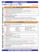
Image B
Go back to Step 4 for instruction.
Demonstrates that the Table Bed has been
assembled into the A-Frame backwards so
the Main Shaft is not resting on the Crossbar
and must be corrected.
Image A
Go back to Step 3 for instruction.
Demonstrates that the Roller Hinges have been
assembled upside down into the Table Bed
and must be corrected.
If your Teeter Inversion Table looks like either of these images, your inversion table has
been misassembled and is unfit for use. Improper assembly could result in serious injury or death!
WARNING
!
REVISIONS
ENGR
DATE
REV
SHT
ZONE
DESCRIPTION
NMS
10/18/2017
A
1
8D
A1: RELEASE FOR PATENT
PARTS LIST
ITEM
QTY
NET DIMENSIONS/DESCRIPTION NOTE
MATERIAL
SHT
REVISION STATUS
SHT
1
REV
A
8
A
1234567
D
C
B
C
A
D
B
5 3 16 248 7
8
A
1234567
D
C
B
C
A
D
B
5 3 16 248 7
bed on backwards missassembly
SHEET 1 OF 1
REV
PROJECT:
DRAWN
UNLESS OTHERWISE NOTED
SURFACE ROUGHNESS PER ANSI B46.1
DIMENSIONING PER ASME Y14.5-2009
WELD SYMBOLS PER AWS A2.4
FINISH:
UOS 63RMS ON
MACHINED
SURFACES OR
AS PROCURED
.X
.XX
.XXX
ANGLE
EXPECTATIONS PROPRIETARY
THE INFORMATION CONTAINED HEREIN
IS PROPRIETARY TO EXPECTATIONS AND
SHALL NOT BE REPRODUCED IN WHOLE
OR IN PART OR USED FOR ANY PURPOSE
EXCEPT WHEN SUCH USER POSSESSES
DIRECT WRITTEN AUTHORIZATION
FROM EXPECTATIONS LLC
SCALE: FULL
SIZE:
D
A
TOLERANCES
UNLESS NOTED
=
.1
=
.03
=
.005
=
1
NICK SOLLER
FILLET RADII: .005-.010
CORNER BREAK: .005-.010
ALL DIMENSIONS IN INCHES
EXPECTATIONS LLC
PUYALLUP, WA 98391
DRAWING
PROJECT NAME HERE
REVISIONS
ENGR
DATE
REV
SHT
ZONE
DESCRIPTION
NMS
10/18/2017
A
1
8D
A1: RELEASE FOR PATENT
PARTS LIST
ITEM
QTY
NET DIMENSIONS/DESCRIPTION NOTE
MATERIAL
SHT
REVISION STATUS
SHT
1
REV
A
8
A
1234567
D
C
B
C
A
D
B
5 3 16 248 7
8
A
1234567
D
C
B
C
A
D
B
5 3 16 248 7
roller hinges missassembled
SHEET 1 OF 1
REV
PROJECT:
DRAWN
UNLESS OTHERWISE NOTED
SURFACE ROUGHNESS PER ANSI B46.1
DIMENSIONING PER ASME Y14.5-2009
WELD SYMBOLS PER AWS A2.4
FINISH:
UOS 63RMS ON
MACHINED
SURFACES OR
AS PROCURED
.X
.XX
.XXX
ANGLE
EXPECTATIONS PROPRIETARY
THE INFORMATION CONTAINED HEREIN
IS PROPRIETARY TO EXPECTATIONS AND
SHALL NOT BE REPRODUCED IN WHOLE
OR IN PART OR USED FOR ANY PURPOSE
EXCEPT WHEN SUCH USER POSSESSES
DIRECT WRITTEN AUTHORIZATION
FROM EXPECTATIONS LLC
SCALE: FULL
SIZE:
D
A
TOLERANCES
UNLESS NOTED
=
.1
=
.03
=
.005
=
1
NICK SOLLER
FILLET RADII: .005-.010
CORNER BREAK: .005-.010
ALL DIMENSIONS IN INCHES
EXPECTATIONS LLC
PUYALLUP, WA 98391
DRAWING
PROJECT NAME HERE
MISASSEMBLY CHECK

Attach Angle Tether
The tether will come pre-assembled to the A-Frame.
Figure 16: Unfold the adjustable tether and clip it to the
U-Bar on the underside of the Table Bed.
Slide the buckle to lengthen or shorten the strap
depending on your desired maximum angle of inversion.
FIGURE 4
STEP 6 ATTACH ANGLE TETHER
Figure 16
11

FIGURE 4
STEP 7
12
ATTACH COMFORT CUSHION OPTIONAL
Figure 17: Locate the fastening nodes included with the
Comfort Cushion and unscrew the backing from each.
Place the cushion onto the Table Bed aligned with the
designated holes.
Figure 18: Insert a node backing from the back of the Table
Bed through the Table Bed slot and hole in the cushion.
Hold the backing perpendicular to the slot.
Figure 18a & 18b: With the other hand, fasten the node top
onto the backing threads visible from the front of the Table
Bed. Twist the node clockwise to secure it into place in one
of two ways:
1. Static: If you do not want the Comfort Cushion to move
with you as you invert, tighten the node until it is snug. Do
not over-tighten.
2. Responsive: If you want the Comfort Cushion to slide with
you as you invert to encourage body slide at shallower angles,
tighten the node just tight enough to keep it in place, but
loose enough to move within the slot.
Repeat the process above with the three (3) remaining
fastening nodes to finish securing the Comfort Cushion to the
Table Bed.
Be sure to replace the backings onto the nodes when the
Comfort Cushion is removed.
Figure 17
Figure 18
The Comfort Cushion provides a plush, supportive surface for a premium inversion experience without
inhibiting body slide needed for decompression. The included fastening nodes secure the Comfort Cushion
to the Table Bed while still allowing it to move within the tracks of the FitSpine Bed.
CHOKING HAZARD: Small parts - keep out of reach
of children.
WARNING
!
Figure 18a Figure 18b
Spot clean using a soft, slightly damp sponge or cloth. Do not use brushes or abrasive cleaners.
Cleaning & Maintenance

STEP 8
13
ATTACH LUMBAR BRIDGE OPTIONAL
Stabilize the inversion table to prevent rotation
during assembly.
Position the bridge with the Teeter logo at the base and
facing towards you.
Figure 19: First, insert the bottom two notches of the bridge
into the desired horizontal slots on the lower portion of the
Table Bed.
Use of the Lumbar Bridge may impact the rotation of the
table. Set the Angle Tether to a moderate inversion angle
and use a spotter until you are able to find the correct
balance settings and are comfortable with the operation
of the table.
Start in a lower level arch setting and work your way up.
If you feel any discomfort, lower the setting until you are
comfortable or discontinue use.
Figure 21: The Lumbar Bridge works between intermediate
to moderate inversion. Full inversion moves the body away
from the table bed and will reduce the effectiveness of
the bridge.
Figure 20: Bend the bridge to the arch height you desire and
insert the one top notch into the corresponding slot on the
upper portion of the Table Bed.
Modify the positioning and arch height as needed.
NOTE: Long-term storage of the Lumbar Bridge in a high
arch setting may result in distortion of the shape and ability
of the bridge to move to lower arch settings. Store in its flat
position when not in use.
Use Instructions
The Lumbar Bridge provides even deeper decompression and improved alignment benefits. Personalize the
intensity and target zone of the Lumbar Bridge by adjusting the height and position of the arch within the
slots on the Table Bed so it fits comfortably at the small of your back. The Lumbar Bridge can be used with or
without the Comfort Cushion.
Figure 19
Figure 20
Figure 21

14
BEFORE INVERTING
Figure 22
Figure 22a
Watch the Getting Started Videos
The Getting Started Video Portal is a helpful supplement to the Owner’s Manual, with easy-to-follow
instructions on user settings, how to invert, storage and maintenance, and even stretching and exercises
you can do with your Teeter. Access via teeter.com/videos and search Model ‘FX-2’ now!
Ensure Owner’s Manual is Attached
The Owner’s Manual contains important information
on how to use your Teeter Inversion Table, including
how to personalize the user settings, properly secure
and release the Ankle Lock System, and test and adjust
the rotation control.
Figure 22: If the Owner’s Manual is not already attached,
secure the chain to the A-Frame through the
designated hole in the Hinge Plate. Allow the Owner’s
Manual to hang freely on the outside of the A-Frame
Spreader Arms so it doesn’t interfere with the rotation of
the Table Bed.
IMPORTANT: Once attached to the A-Frame, DO NOT
remove the Owner’s Manual. It should remain permanently
attached to your inversion table to serve as a reference
for all users in regard to proper adjustment and use of
the equipment.
WARNING
!
Read the Owner’s Manual thoroughly before using your
Teeter Inversion Table. Improper settings could result
in serious injury or death!

15
HOW TO SUBMIT YOUR REGISTRATION:
Step 1
Fill out this information for your own records.
Step 2
Go online to teeter.com/warranty to register your warranty.
Handling and transportation costs related to product warranty service only are covered by this warranty. This warranty does
not cover damage resulting from improper handling, assembly, or installation, repairs made by others, accident, misuse,
or abuse. Under no circumstances shall Teeter, or any other party involved in the sale of this product, have any liability for
incidental or consequential damage arising from breach of an express or implied warranty on any Teeter product.
EXCEPT AS SET FORTH ABOVE, NO WARRANTY IS GIVEN WITH RESPECT TO ANY TEETER PRODUCT, AND ALL
EXPRESS WARRANTIES ARE DISCLAIMED. This warranty shall be governed by the laws of the State of Washington,
USA. To the extent this warranty is found not to be enforceable, it shall be deemed revised to the extent necessary to
make it enforceable. This warranty and any controversy or claim arising out of this warranty or its interpretation shall be
governed by the laws of the State of Washington, USA. Any controversy or claim arising out of or relating to this warranty,
its interpretation, or any alleged breach thereof, which cannot be amicably settled between Teeter and the owner within
sixty (60) days of written notice by the aggrieved party to the other, shall be finally settled by arbitration submitted to three
(3) arbitrators selected from the panels of the arbitrators of the American Arbitration Association located closest to Teeter’s
principal place of business.
Some states do not allow the exclusion of incidental or consequential damage from a warranty, so the above limitation or
exclusion may not apply to you. Some states do not allow limitations on how long an implied warranty lasts, so the above
limitation may not apply to you. This warranty gives you specific legal rights, and you may also have other rights which may
vary from state to state.
AUSTRALIA: Our goods come with guarantees that cannot be excluded under the Australian Consumer Law. You are
entitled to a replacement or refund for a major failure and for compensation for any other reasonably foreseeable loss or
damage. You are also entitled to have the goods repaired or replaced if the goods fail to be of acceptable quality and the
failure does not amount to a major failure.
Date of Purchase
Product & Model
Dealer Name
Serial No. (located on the back of the Table Bed)
YEAR
5
W
A
R
R
A
N
T
Y
FULL
During the period starting with the day of retail purchase and continuing for five (5) years,
Teeter extends to the owner a repair and replacement warranty against manufacturing defects
in materials, workmanship, fabrics and padding. Teeter will repair or replace any such defect
and will pay the costs of all parts, labor and transportation. If a repair or replacement is not
commercially practical or cannot timely be made, then Teeter will, at the original Purchaser’s
option, replace with a comparable product or refund the purchase price.
The Teeter warranty set forth below and on Teeter’s website applies to US and Canadian customers only.
For international customers, please consult your local distributor for warranty information which will vary
depending on country.
Maximize your results with your Teeter Inversion Table
Go to teeter.com and register your warranty to gain
FREE access to this downloadable exercise guide.
If you are unable to go online, you can request a warranty card to be mailed to you by calling Customer Service at 800-847-0143.
Please DO NOT mail this to Teeter.
FREE DIGITAL GUIDE AVAILABLE!
FULL 5 YEAR WARRANTY

This page intentionally left blank.

This page intentionally left blank.

U.S. and Foreign Patents Apply. Teeter and Teeter logo are registered trademarks of Teeter. Specifications subject to change without notice.
© COPYRIGHT 2020 Teeter. International Law Prohibits Any Copying. LI2101 0420-0
Teeter Decompression Devices are multiple user, reusable devices for home use, intended to provide traction to the spine while stretching the para-spinal muscles and soft tissues.
The devices provide non-powered traction and are meant for use by adults.
Use of the Teeter Decompression Devices is indicated for the following conditions: back pain, muscle tension, degenerative disc disease, spinal degenerative joint disease, spinal stenosis,
herniated disc, spinal curvature due to tight muscles, sciatica, muscle spasm, and facet syndrome.
Medical Device Safety Service
GmbH
Schiffgraben 41
30175 Hannover
Germany
Tel. +49 511 62628630
EC REP
Any modification to this device will void the UL Listing.
This product is Listed by
Underwriters Laboratories Inc.
Representative samples of this
product have been evaluated
by UL and meet applicable
safety standards.
This product is Listed by
Underwriters Laboratories Inc.
Representative samples of this
product have been evaluated
by UL and meet applicable
safety standards.
This product is Listed by
Underwriters Laboratories Inc.
Representative samples of this
product have been evaluated
by UL and meet applicable
safety standards.
This product is Listed by
Underwriters Laboratories Inc.
Representative samples of this
product have been evaluated
by UL and meet applicable
safety standards.
If you have any trouble assembling the equipment, or questions
about its use, please contact customer service.
USA: 800-847-0143 or info@teeter.com (English language)
International: info@teeterintl.com
Hours of Operation (Monday - Friday 8am - 4pm PST)
USA: Teeter
9713 233rd Avenue East Ste A
Bonney Lake, WA 98391
Toll Free: 800-847-0143
Fax: 800-847-0188
teeter.com | info@teeter.com
Distributed by:
Costco Wholesale Corporation
P.O. Box 34535
Seattle, WA 98124-1535
USA
1-800-774-2678
www.costco.com
Costco Wholesale Canada Ltd.*
415 W. Hunt Club Road
Ottawa, Ontario
K2E 1C5, Canada
1-800-463-3783
www.costco.ca
* faisant affaire au Québec sous le nom les Entrepôts Costco
Importado por:
Importadora Primex S.A. de C.V.
Blvd. Magnocentro No. 4
San Fernando La Herradura
Huixquilucan, Estado de México
C.P. 52765
RFC: IPR-930907-S70
(55)-5246-5500
www.costco.com.mx
Costco Wholesale Australia Pty Ltd
17-21 Parramatta Road
Lidcombe NSW 2141
Australia
www.costco.com.au
Costco Wholesale UK Ltd /
Costco Online UK Ltd
Hartspring Lane
Watford, Herts
WD25 8JS
United Kingdom
01923 213113
www.costco.co.uk
Costco Wholesale Spain S.L.U.
Polígono Empresarial Los Gavilanes
C/ Agustín de Betancourt, 17
28906 Getafe (Madrid) España
NIF: B86509460
900 111 155
www.costco.es
Costco Wholesale Iceland ehf.
Kauptún 3-7, 210 Gardabaer
Iceland
www.costco.is
Costco France
1 avenue de Bréhat
91140 Villebon-sur-Yvette
France
01 80 45 01 10
www.costco.fr
Costco Wholesale Japan Ltd.
3-1-4 Ikegami-Shincho
Kawasaki-ku, Kawasaki-shi,
Kanagawa 210-0832 Japan
0570-032600
www.costco.co.jp
Costco Wholesale Korea, Ltd.
40, Iljik-ro
Gwangmyeong-si
Gyeonggi-do, 14347, Korea
1899-9900
www.costco.co.kr
Costco President Taiwan, Inc.
No. 656 Chung-Hwa 5th Road
Kaohsiung, Taiwan
Company Tax ID: 96972798
449-9909 or 02-449-9909 (if cellphone)
www.costco.com.tw
Shanghai Minhang Costco Trading Co., Ltd
No. 235, ZhuJian Road
Minhang District, Shanghai
China 201106
+86-21-6257-7065
/