Page is loading ...

SNA5000A Series
Vector Network Analyzer
User Manual
E03D


SNA5000A User Manual
www.siglent.com 1
Content
Content .......................................................................................................................................... 1
1 Copyright ............................................................................................................................... 8
2 Safety Requirement .............................................................................................................. 9
2.1 Safety terms and symbols ........................................................................................ 9
2.2 Operating environment ........................................................................................... 10
2.3 Cooling requirement ............................................................................................... 11
2.4 AC power supply .................................................................................................... 11
2.5 Power supply and grounding .................................................................................. 11
2.6 Calibration ............................................................................................................... 12
2.7 Cleaning .................................................................................................................. 12
2.8 Exceptional conditions ............................................................................................ 12
3 Product Introduction........................................................................................................... 13
3.1 General Description ................................................................................................ 13
3.2 Features .................................................................................................................. 13
4 User Manual Overview ........................................................................................................ 15
5 Quick Start ........................................................................................................................... 17
5.1 Dimensions ............................................................................................................. 17
5.2 Power supply .......................................................................................................... 18
5.3 Front panel.............................................................................................................. 19
5.3.1 Functional keyboard .............................................................................................. 20
5.3.2 Digital keyboard .................................................................................................... 21
5.3.3 Power switch ......................................................................................................... 21
5.3.4 RF connectors ....................................................................................................... 22
5.4 Rear panel .............................................................................................................. 23
5.5 OCXO option installation guide .............................................................................. 25
5.6 User interface ......................................................................................................... 26
5.6.1 Active entry ............................................................................................................ 27
5.6.2 Value of marker ..................................................................................................... 27
5.6.3 Trace State ............................................................................................................ 27
5.6.4 Channel State........................................................................................................ 28
5.6.5 Hardkeys ............................................................................................................... 28
5.6.6 Function Keys........................................................................................................ 28
5.6.7 Label Page ............................................................................................................ 28
5.6.8 Window State ........................................................................................................ 29
5.6.9 Stimulus Range ..................................................................................................... 29

SNA5000A User Manual
2 www.siglent.com
5.6.10 Status Bar .............................................................................................................. 29
5.6.11 Message Bar ......................................................................................................... 29
5.6.12 Graffiti Function ..................................................................................................... 30
5.7 Touch Screen .......................................................................................................... 33
5.8 Help Information ..................................................................................................... 33
6 Set Up a Measurement ....................................................................................................... 34
6.1 Measurement parameters ...................................................................................... 34
6.1.1 S parameters ......................................................................................................... 34
6.1.2 Balanced Measurement ........................................................................................ 35
6.1.3 Receiver Measurement ......................................................................................... 43
6.1.4 Wave (Receivers notation) .................................................................................... 43
6.2 Frequency range .................................................................................................... 45
6.2.1 Set the frequency range ........................................................................................ 45
6.2.2 CW time sweep or power sweep........................................................................... 45
6.2.3 Frequency resolution ............................................................................................. 46
6.3 Power level ............................................................................................................. 46
6.4 Sweep ..................................................................................................................... 48
6.4.1 Points .................................................................................................................... 49
6.4.2 Sweep type ............................................................................................................ 49
6.5 Trigger ..................................................................................................................... 52
6.5.1 Trigger Settings ..................................................................................................... 52
6.5.2 Trigger source ....................................................................................................... 53
6.5.3 Trigger Range ....................................................................................................... 53
6.5.4 Channel Settings ................................................................................................... 54
6.5.5 Trigger mode ......................................................................................................... 54
6.5.6 External and auxiliary triggers ............................................................................... 56
6.6 Data format ............................................................................................................. 59
6.6.1 Display format ....................................................................................................... 59
6.6.2 LF Cartesian coordinates display format .............................................................. 59
6.6.3 Polar coordinates .................................................................................................. 61
6.6.4 Smith circle diagram .............................................................................................. 62
6.7 Scale ....................................................................................................................... 64
6.7.1 Scale/reference level and position ........................................................................ 64
6.7.2 Scaling coupling .................................................................................................... 65
6.7.3 Electrical delay ...................................................................................................... 67
6.7.4 Amplitude offset and amplitude slope ................................................................... 67
6.7.5 Phase deviation ..................................................................................................... 68
6.7.6 Divisions ................................................................................................................ 68
6.7.7 Scale type .............................................................................................................. 69

SNA5000A User Manual
www.siglent.com 3
6.8 Avg BW ................................................................................................................... 69
6.8.1 Overview ............................................................................................................... 69
6.8.2 Averaging .............................................................................................................. 70
6.8.3 IF Bandwidth ......................................................................................................... 70
6.8.4 Smoothing ............................................................................................................. 72
6.9 Preset instructions .................................................................................................. 72
7 Measurement Calibration ................................................................................................... 75
7.1 Overview ................................................................................................................. 75
7.2 Calibration type ....................................................................................................... 76
7.3 Checking Calibration Status ................................................................................... 79
7.3.1 Execution Status of Error Correction for Each Channel ....................................... 79
7.3.2 Execution Status of Error Correction for Each Trace ............................................ 81
7.3.3 Acquisition Status of Calibration Coefficient for Each Channel ............................ 81
7.3.4 Procedure to turn on/off calibration property display ............................................ 82
7.4 S parameter calibration .......................................................................................... 83
7.4.1 S parameter calibration Kit management .............................................................. 83
7.4.2 S Parameter calibration wizard ............................................................................. 95
7.4.3 Open Response Calibration .................................................................................. 98
7.4.4 Short circuit response calibration .......................................................................... 99
7.4.5 Full 1 port OSL calibration ..................................................................................... 99
7.4.6 Transmission response calibration (two ports) ................................................... 100
7.4.7 Enhanced response calibration (two ports) ......................................................... 101
7.4.8 SOLT calibration (two ports) ................................................................................ 102
7.4.9 SOLR unknown through calibration (two ports) .................................................. 103
7.4.10 TRL Direct Reflection Transmission Line Calibration (Two Ports) ...................... 104
7.5 Internal source power calibration ......................................................................... 105
7.6 Receiver calibration .............................................................................................. 106
7.7 Port extension ....................................................................................................... 108
7.8 Fixture measurement function ............................................................................... 111
7.9 Adapter removal / insertion function ..................................................................... 116
7.10 Ecal ....................................................................................................................... 118
7.10.1 ECal Overview..................................................................................................... 118
7.10.2 ECal Config ......................................................................................................... 119
7.10.3 Confidence Check ............................................................................................... 120
7.10.4 Orientation ........................................................................................................... 121
7.10.5 Characterization .................................................................................................. 122
8 Data Analysis ..................................................................................................................... 124
8.1 Marker ................................................................................................................... 124

SNA5000A User Manual
4 www.siglent.com
8.1.1 Ordinary marker: ................................................................................................. 124
8.1.2 Reference marker: .............................................................................................. 124
8.1.3 Marker setting:..................................................................................................... 124
8.1.4 Marker function:................................................................................................... 127
8.1.5 Marker search function: ....................................................................................... 127
8.2 Mathematical operation ........................................................................................ 133
8.3 Conversion............................................................................................................ 133
8.4 Equation editor ..................................................................................................... 136
8.5 Trace statistics ...................................................................................................... 144
8.6 Limit test ............................................................................................................... 144
8.7 Ripple limit test ..................................................................................................... 147
8.8 Bandwidth limit test ............................................................................................... 149
8.9 Time domain ......................................................................................................... 150
8.9.1 Transform ............................................................................................................ 150
8.9.2 Gating .................................................................................................................. 152
8.9.3 Window ................................................................................................................ 154
8.9.4 Coupling .............................................................................................................. 156
8.9.5 Marker ................................................................................................................. 157
9 Guide For the TDR Option ................................................................................................ 159
9.1 Overview ............................................................................................................... 159
9.2 Open/Close/Preset TDR Option ........................................................................... 160
9.3 TDR Setup Wizard ................................................................................................ 161
9.4 Calibration for TDR Option ................................................................................... 162
9.4.1 Deskew ................................................................................................................ 162
9.4.2 Deskew & Loss Compensation ........................................................................... 163
9.5 TDR Channel Setup ............................................................................................. 164
9.5.1 DUT Topology ...................................................................................................... 165
9.5.2 DUT Length ......................................................................................................... 165
9.5.3 Stimulus Magnitude in Time Domain .................................................................. 166
9.5.4 Port Impedance ................................................................................................... 166
9.5.5 Velocity Factor & Dielectric Constant .................................................................. 167
9.5.6 Power Level......................................................................................................... 167
9.5.7 Average ............................................................................................................... 167
9.5.8 IF Bandwidth ....................................................................................................... 168
9.5.9 Trigger Mode ....................................................................................................... 168
9.6 TDR Trace Setup .................................................................................................. 168
9.6.1 Select a Trace ..................................................................................................... 168
9.6.2 Scale Management ............................................................................................. 169
9.6.3 Memory Trace Management ............................................................................... 170

SNA5000A User Manual
www.siglent.com 5
9.6.4 Measure Parameter & Format ............................................................................. 170
9.6.5 Stimulus in Time Domain .................................................................................... 171
9.6.6 Smoothing ........................................................................................................... 172
9.6.7 Trace Allocation ................................................................................................... 172
9.6.8 Trace Setup Coupling .......................................................................................... 173
9.6.9 Time Domain Gating ........................................................................................... 173
9.7 TDR Data Analysis & Output ................................................................................ 174
9.7.1 Marker Setup ....................................................................................................... 174
9.7.2 Rise Time Search ................................................................................................ 174
9.7.3 Delta Time Search ............................................................................................... 174
9.7.4 Peeling ................................................................................................................ 175
9.7.5 File & Data Output ............................................................................................... 175
9.8 Eye Diagram Simulation ....................................................................................... 176
9.8.1 Overview ............................................................................................................. 176
9.8.2 Stimulus Bit Pattern ............................................................................................. 177
9.8.3 Stimulus Signal Setup ......................................................................................... 178
9.8.4 Eye Diagram Analysis ......................................................................................... 179
9.8.5 Eye Diagram Scale Management ....................................................................... 179
9.8.6 Mask Test for Eye Diagram ................................................................................. 180
9.8.7 Jitter & Statistical Eye Diagram ........................................................................... 180
9.9 TDR Advanced Waveform Function ..................................................................... 182
9.9.1 View point ............................................................................................................ 182
9.9.2 Emphasis/De-emphasis ...................................................................................... 183
9.9.3 De-embedding ..................................................................................................... 183
9.9.4 Equalization ......................................................................................................... 184
9.10 Hot TDR ................................................................................................................ 186
10 Guide For the SA Option .................................................................................................. 189
10.1 Overview ............................................................................................................... 189
10.2 User Interface ....................................................................................................... 189
10.3 Create a Spectrum Analysis Channel .................................................................. 190
10.4 Spectrum Analyzer Settings ................................................................................. 191
10.4.1 SA Tab Setting ..................................................................................................... 192
10.4.2 SA Tab Processing setup .................................................................................... 194
10.4.3 Source Tab .......................................................................................................... 197
10.4.4 Advanced Tab ...................................................................................................... 199
10.4.5 Trace setup ......................................................................................................... 200
10.5 Spectrum Analysis measurement ......................................................................... 203
10.5.1 Marker → SA ....................................................................................................... 203
10.5.2 Channel Power .................................................................................................... 204

SNA5000A User Manual
6 www.siglent.com
10.5.3 ACPR .................................................................................................................. 206
10.5.4 Occupied BW ...................................................................................................... 208
11 The Frequency Offset Mode............................................................................................. 210
11.1 Overview ............................................................................................................... 210
11.2 Frequency Offset Mode ........................................................................................ 210
11.2.1 Frequency Offset settings ................................................................................... 211
11.2.2 Setup Examples .................................................................................................. 214
12 Scalar Mixer Measurements(SMM Option) ..................................................................... 216
12.1 Create an SMM measurement ............................................................................. 216
12.2 Configure the Scalar mixer setup ......................................................................... 218
12.2.1 Sweep Tab – Mixer Measure Setup box ............................................................. 219
12.2.2 Power Tab - Mixer Measure Setup box ............................................................... 220
12.2.3 Mixer Frequency Tab- Mixer Measure Setup box ............................................... 221
12.2.4 Mixer Setup Tab- Mixer Measure Setup box ....................................................... 224
12.3 Do the Source Power Cal of the SMM mode (optional) ....................................... 227
12.4 Do the Receiver Cal of the SMM mode (optional) ............................................... 227
12.5 Do the SMM Calibration ....................................................................................... 227
12.5.1 Overview ............................................................................................................. 227
12.5.2 Procedure Using Mechanical Calibration Kit ....................................................... 228
12.5.3 Checking Calibration Status ................................................................................ 229
13 Pulse Measurement (PM Option) ..................................................................................... 230
13.1 Overview ............................................................................................................... 230
13.2 Pulse Measurement Settings ............................................................................... 231
13.2.1 Pulse Measurement ............................................................................................ 231
13.2.2 Pulse Timing ........................................................................................................ 231
13.2.3 Properties ............................................................................................................ 232
13.2.4 Measurement Timing ........................................................................................... 232
13.3 RF&IF Path Gain dialog ....................................................................................... 233
14 Save and Recall ................................................................................................................. 234
15 System setting ................................................................................................................... 237
15.1 Communication interface setting .......................................................................... 237
15.2 Firmware upgrade ................................................................................................ 238
15.3 Date/Time setting .................................................................................................. 238
15.4 Screenshot setting ................................................................................................ 239
15.5 Preset ................................................................................................................... 239
15.6 Factory Reset ....................................................................................................... 239
15.7 Help information ................................................................................................... 240

SNA5000A User Manual
www.siglent.com 7
15.7.1 Help and About .................................................................................................... 240
15.7.2 Message Setting ................................................................................................. 240
15.7.3 View Message ..................................................................................................... 241
15.8 Buzzer ................................................................................................................... 241
15.9 Self-Test ................................................................................................................ 241
15.9.1 Key and touch screen test ................................................................................... 241
15.9.2 Performance test ................................................................................................. 241
15.9.3 System language ................................................................................................ 247
16 Service and Support ......................................................................................................... 248
16.1 Ordering and activating the options ..................................................................... 248
16.2 Warranty overview ................................................................................................ 249
16.3 Contact SIGLENT ................................................................................................. 249

SNA5000A User Manual
8 www.siglent.com
1 Copyright
⚫ SIGLENT TECHNOLOGIES CO., LTD All Rights Reserved.
⚫ SIGLENT is the registered trademark of SIGLENT TECHNOLOGIES CO., LTD.
⚫ Information in this publication replaces all previously corresponding material.
⚫ SIGLENT reserves the right to modify or change parts of or all the specifications or pricing
policies at the company’s sole decision.
⚫ Any method of copying, extracting, or translating the contents of this manual is not allowed
without the permission of SIGLENT.

SNA5000A User Manual
www.siglent.com 9
2 Safety Requirement
This section contains information and warnings that must be observed to keep the instrument
operating under the corresponding safety conditions. In addition to the safety precautions specified in
this section, you also have to follow common safe operating procedures.
2.1 Safety terms and symbols
When the following terms or symbols appear on the front panel, rear panel, or this manual, it
indicates particular attention should be paid.
Indicates potential injuries or hazards that may happen.
Indicates electric shock that may happen.
Indicates measurement grounding
Indicates safety grounding.
This is a start/standby switch. Press the switch, the VNA will switch between the
working state and the standby state. The switch could not power off the device, to
completely power off the VNA, the power cord must be removed from the AC
socket.
Indicates “AC”.
CAUTION
Indicates potential damages to the instrument or other property that may happen.
WARNING
Indicates potential injuries or hazards that may happen.

SNA5000A User Manual
10 www.siglent.com
2.2 Operating environment
Use in a clean and dry indoor environment with an ambient temperature range from 0°C to 40°C.
Note: Direct sunlight, electric heaters, and other direct heat sources, should be considered when
evaluating the ambient temperature.
WARNING: Do not operate the VNA in an explosive, dusty or humid environment.
This instrument meets the EN 61010-1 standard, and has the following restrictions:
Installation (overvoltage) category: Class II (electric supply connector) and Class I (measure terminal)
Pollution level: Class II
Protection level: Class I
Note:
Installation (overvoltage) category Class II indicates the local supply level is suitable for equipment
connected to the AC power supply.
Installation (overvoltage) category Class I indicates the signal levels suitable for terminals connected
to the RF source.
Pollution level Class II indicates it only occurs in a dry and non-conductive environment, sometimes
we should consider the temporary conductivity caused by concentration.
Protection level Class I indicates grounding equipment, it prevents electric shock by connecting the
equipment to the ground wire.
CAUTION: Do not apply excessive pressure or strike the surface of the touch
screen.
CAUTION: Do not exceed the maximum voltage marked on the front panel
connectors.

SNA5000A User Manual
www.siglent.com 11
2.3 Cooling requirement
This instrument is cooled through a built-in fan. To keep adequate ventilation, a gap of at least 15 cm
should be left on both sides, as well as the front and rear panels of the instrument.
CAUTION: Do not block the vents located along the side and real panel of the
instrument.
CAUTION: Do not let any external objects enter the instrument through the vents.
2.4 AC power supply
The instrument accepts 100-240V, 50/60/400Hz AC power. The maximum power consumption is
90W with complete options.
Note: The instrument can operate within the following input ranges:
Voltage range:
90 - 264 Vrms
90 - 132 Vrms
Frequency range:
47 - 63 Hz
380 - 420 Hz
2.5 Power supply and grounding
The instrument has a three-terminal plug and an IEC320 (Type C13) standard connector for the input
power and grounding connections. The grounding terminal on the socket is directly connected to the
instrument shell. To prevent electric shock, the plug must be inserted into a well-grounded socket.
Please use the power cord provided to connect the instrument to the power source.
WARNING: Danger of electric shock!
Disconnected or broken internal or external grounding wires will increase the risk
of electric shock. It is strictly forbidden to destroy the protective grounding wire
or safety grounding terminals.

SNA5000A User Manual
12 www.siglent.com
The location of the instrument should be convenient to access the power supply. To completely
power off the instrument, the power cord should be removed from the power socket of the instrument.
When the instrument is idle for long durations, it is recommended to unplug the power cord from the
AC socket.
CAUTION: The RF connector’s shell on the front panel is connected to the
instrument’s shell, and then connected to the earth ground.
2.6 Calibration
The recommended calibration cycle is one year. Calibration should only be performed by qualified
personnel.
2.7 Cleaning
Only a soft damp cloth without any chemical/corrosive substances can be used to clean the
instrument. Do not clean or use the product in wet environments. To avoid electric shock, unplug the
power cord from the AC socket before cleaning.
WARNING: Danger of electric shock!
Do not disassemble the instrument. Maintenance must be carried out by qualified
personnel only.
2.8 Exceptional conditions
Use the instrument only for the purpose specified by the manufacturer. Do not use if the instrument
has visible damage or has endured severe transportation vibration. If the device is suspected to be
damaged, please disconnect the power cord and contact your local SIGLENT office. To operate the
instrument correctly, all instructions and marks should be read carefully.
WARNING: Use of the instrument for purposes unspecified by the manufacturer
may damage the instrument.

SNA5000A User Manual
www.siglent.com 13
3 Product Introduction
3.1 General Description
The SIGLENT SNA5000A series of vector network analyzers includes the following models: SNA5002A,
SNA5004A, SNA5012A, SNA5014A, SNA5022A, SNA5032A .That have a frequency range of 9kHz to
26.5GHz, which support 2/4-port scattering, differential, and time-domain parameter measurements.
The SNA5000A series are ideal for determining the Q-factor, bandwidth, and insertion loss of a filter.
They feature impedance conversion, movement of measurement plane, limit testing, ripple test, fixture
simulation, and adapter removal / insertion adjustments. The VNAs have five sweep types: Linear-
Frequency mode, Log-Frequency mode, Power-Sweep mode, CW-Time mode, and Segment-Sweep
mode. They also support scattering-parameter correction of SOLT, SOLR, TRL, Response, and
Enhanced Response for increased flexibility in R&D and manufacturing applications. The frequency
range of each model is shown in the table below.
Model
Ports
Frequency range
SNA5002A
2
9kHz-4.5GHz
SNA5004A
4
9kHz-4.5GHz
SNA5012A
2
9kHz-8.5GHz
SNA5014A
4
9kHz-8.5GHz
SNA5022A
2
100kHz-13.5GHz
SNA5032A
2
100kHz-26.5GHz
3.2 Features
⚫ Frequency range : 9 kHz-26.5GHz
⚫ Ports : 2/4
⚫ Frequency resolution : 1 Hz
⚫ Level resolution : 0.05 dB
⚫ Range of IFBW : 10 Hz-3 MHz
⚫ Setting range of output level : -55 dBm ~ +10 dBm
⚫ Dynamic range : 125 dB
⚫ Trace noise: 0.003 dBrms , 0.05 rms

SNA5000A User Manual
14 www.siglent.com
⚫ Types of calibration : Response calibration, Enhanced Response calibration, Full-one port
calibration, Full-two port calibration, Full-three port calibration, Full-four port calibration, TRL
calibration
⚫ Types of measurement :Scattering-parameter measurement, differential-parameter
measurement, receiver measurement, time-domain parameter analysis, limit test, ripple test,
impedance conversion, fixture simulation, adapter removal/insertion, spectrum analysis
frequency offset, scalar mixer measurement, Pulse measurement.
⚫ Optional Bias-Tees
⚫ Interface: LAN, USB Device, USB Host (USB-GPIB)
⚫ Remote control: SCPI / Labview / IVI based on USB-TMC / VXI-11 / Socket / Telnet / Webserver.
⚫ 12.1-inch touch screen
⚫ Video output: HDMI

SNA5000A User Manual
www.siglent.com 15
4 User Manual Overview
Main Contents
Chapter1. Copyright
Chapter2. Safety Requirement
Chapter3. Product Introduction
This chapter introduces the characteristic index and function of vector network analysis.
Chapter4. User Manual Overview
This chapter introduces the chapters of the user manual.
Chapter5. Quick Start
This chapter introduces the appearance and size of the vector network analyzer, the basic
operation of the front and rear panels, user interface, buttons, and touch screen.
Chapter6. Set Up a Measurement
This chapter describes the measurement function, sweeping trigger setting, and other functions
of the vector network analyzer, and introduces the functions under each menu in detail.
Chapter7. Measurement Calibration
This chapter introduces the different calibration methods of S parameters, power calibration
methods, test fixture, and other functions of vector network analyzer in detail.
Chapter8. Data Analysis
This chapter introduces the mathematical analysis function, including time-domain analysis,
windows, coupling, markers, and other functions.
Chapter9. Guide For the TDR Option
This chapter introduces how to use the TDR option.
Chapter10. Guide For the SA Option
This chapter introduces how to use the SA option.
Chapter11. The Frequency Offset Mode
This chapter introduces the function of SNA Sources tune to frequencies that are different
(offset) from the VNA Receivers.
Chapter12. Scalar Mixer Measurements(SMM Option)
This chapter introduces how to do the Scalar Mixer Measurement.

SNA5000A User Manual
16 www.siglent.com
Chapter13. Pulse Measurement(PM Option)
This chapter introduces how to use pulse measurements to test some DUT that cannot be tested
using continuous signals.
Chapter14. Save and Recall
This chapter introduces the data save and recall processes.
Chapter15. System Setting
This chapter provides information about the system settings.
Chapter16. Service and Support
This chapter provides information about service and support.

SNA5000A User Manual
www.siglent.com 17
5 Quick Start
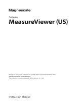
5.1 Dimensions
Figure 5–1 Front view and side view
Figure 5–2 Rear panel view

SNA5000A User Manual
18 www.siglent.com
5.2 Power supply
The equipment accepts 100-240V, 50/60Hz AC power supplies. Please use the power cord provided
to connect the instrument to the power source as shown in the figure below.
Power
Interface
Figure 5–3 Power interface
/