Page is loading ...

Model Number
T-3202
Capacity
2 Ton
2 YEAR LIMITED WARRANTY
For a period of two (2) years from date of purchase, Shinn Fu Co. of America,
Inc. will repair or replace, at its option, without charge, any of its products which fails due
to a defect in material or workmanship, or which fails to conform to any implied warranty
not excluded hereby.
Performance of any obligation under this warranty may be obtained by returning
the warranted product, freight prepaid, to Shinn Fu Co. of America, Inc. Warranty
Service Department, 10939 N. Pomona Ave., Kansas City, MO 64153.
Except where such limitations and exclusions are specically prohibited by
applicable law, (1) the CONSUMER’S SOLE AND EXCLUSIVE REMEDY SHALL BE
THE REPAIR OR REPLACEMENT OF DEFECTIVE PRODUCTS AS DESCRIBED
ABOVE, and (2) Shinn Fu Co. of America, Inc. SHALL NOT BE LIABLE FOR ANY
CONSEQUENTIAL OR INCIDENTAL DAMAGE OR LOSS WHATSOEVER, and (3) THE
DURATION OF ANY AND ALL EXPRESSED AND IMPLIED WARRANTIES, INCLUDING
WITHOUT LIMITATION, ANY WARRANTIES OF MERCHANTABILITY AND FITNESS
FOR A PARTICULAR PURPOSE, IS LIMITED TO A PERIOD OF NINETY (90) DAYS
FROM DATE OF PURCHASE.
Some states do not allow limitations on how long an implied warranty lasts, so
the above limitation may not apply to you. Some states do not allow the exclusion or
limitation of incidental or consequential damages, so the above limitation or exclusion
maynotapplytoyou.Thiswarrantygivesyouspeciclegalrights,andyoumayalso
have other rights which vary from state to state.
8
Operating Instructions & Parts Manual
Shinn Fu Company of America, Inc.
10939 N. Pomona Ave.
Kansas City, MO 64153
Phone (888)332-6419, fax (816)891-6599 Printed in China
Heavy Duty
Engine Crane
© Sept. 2018
To avoid crushing and related injuries:
NEVER work on, under or around a
vehicle supported by dollies.
WARNING
!
WARNING: Cancer and Reproductive Harm.
AVERTISSEMENT: Cancer et dommages au système reproducteu
r.
ADVERTENCIA: Cáncer y daño reproductivo.
www.P65Warnings.ca.gov

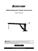
Fig. 1 - Engine Crane Nomenclature
2 3
Save these instructions. For your
safety, read, understand, and follow the
information provided with and on this
engine crane. The owner and operator of
this equipment shall have an understanding
of this engine crane and safe operating
procedures before attempting to use. The
owner and operator shall be aware that
use and repair of this product may require
special skills and knowledge. Instructions
and safety information shall be conveyed
in the operator’s native language before
use of this engine crane is authorized. If
any doubt exists as to the safe and proper
use of this product, remove from service
immediately. Inspect before each use.
Do not use if broken, bent, cracked or
damaged parts are noted. Any engine
crane that appears damaged in any way,
or operates abnormally shall be removed
from service immediately. If the engine
crane has been or suspected to have been
subjected to a shock load (a load dropped
suddenly, unexpectedly), immediately
discontinue use until product has been
checked by an authorized service center. It
is recommended that an annual inspection
be done by qualied personnel. Labels
and Owners Manuals are available from
manufacturer.
PRODUCT DESCRIPTION
This Pro-Lift Engine Crane is designed to
safely lift and lower rated capacity engines.
Welded steel tube construction, safety
hook, steel castors ensure safety, strength
and stability.
BEFORE USE (refer to Fig.1 and
Replacement Parts Illustration on Page 6
for location of components)
1. Inspect crane before each use. Do
not use if bent, broken or cracked
components are noted. Ensure that
casters and boom move freely. Check
for and tighten any loose assemblies.
2. Verify that the product and the application
are compatible, if in doubt call Pro-Lift
Customer Support @ (888)332-6419.
BEFORE USE (continued)
3. Before using this product, read the
owner’s manual completely and
familiarize yourself thoroughly with the
product and the hazards associated with
its improper use.
Read, understand and follow all warnings
and instructional material provided on
and with this product. This engine crane
is intended to be used to lift and lower
rated capacity automotive and light truck
engines. Do not exceed rated capacity
for each boom position. When removing
and installing engines, ensure that
crane’s power unit is not jammed against
vehicle. Use only on hard, level surfaces
capable of supporting the load. Use only
chains and slings with a capacity equal to
or greater than that of the crane. If loaded
crane must be moved, make certain
that load is stable, is in lowest possible
position and is moved over a smooth,
hard level surface. Make sure that
boom is fully lowered before checking or
addinguidtopowerunit.Avoidshock
loads caused by the rapid opening and
closing of release valve. Shock loads
may cause the load to swing, causing the
cranetoipviolently,bendorbreak.Do
not allow load to swing or drop violently
while lowering or moving. Do not stand
over loaded boom nor in its intended line
of travel. Do not modify this equipment.
Failure to heed this warning may result
in personal injury as well as property
damage.
• Leer, comprender, y seguir las
instrucciónes antes de utilizar el
aparato.
• El manual de instrucciónes y la
información de seguridad deben
estar comunicado en lengua del
operador antes del uso.
• No seguir estas indicaciónes puede
causar daños personales o materiales.
SPECIFICATIONS
Model Boom
Position Capacity Boom Length
T-3202
1
Max. Hook
Height
Min. Hook
Height
1 Ton
9”
0”
74 7/8”
93 1/4”
87 3/8“
81 1/8”
39 3/8”
4
2 Ton 26 3/4”
34 1/4”2 3/8”1 1/2 Ton2
3
49 1/4”0”1/2 Ton
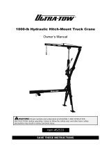
Fig. 2 - Engine Crane Storage Position
Instruction on how to transform the
crane into storage position: (see Fig. 2)
1. Lower boom to its minimum height.
2. Remove forward most lock pin (Ref. No.
10ingure3)fromeachlegextension.
3. Carefully lift each leg into the upright
position.
4.Reinstalllockpin(Ref.No.10ingure
3) into middle hole on base frame leg
connection.
WARNING
!
ADVERTENCIA
!
Boom Extension
Rear Caster
Middle
Caster
Leg Extensions
Upright
Support Strut
Boom
Hydraulic Unit
Chain/Hook
Assembly
Front Caster
Handle
Base
Load Restraint

4
OPERATION
1. Ensure application is compatible with
product.
2. Read, understand and follow engine
removal and installation instructions
provided by vehicle service or shop
manual.
3. Chains used in conjunction with this
product shall have a rated capacity
greater than the weight of the object
being lifted. Secure chain/hook
assembly to appropriate lifting point on
engine. Refer to vehicle service or shop
manual for the location of appropriate lift
points. Ensure load is centered.
4. When ready to remove engine, turn
releasevalveclockwiseuntilrm.Pump
handle until load is securely supported
by crane.
5. Remove engine, then immediately
transfer the engine to appropriate
engine support device (engine stand).
6. Check to ensure stand is secure before
working on or around.
MAINTENANCE
Important: Use only a good grade *hy-
draulic jack oil. Avoid mixing different
typesofuidandNEVERusebrakeuid,
turbineoil,transmissionuid,motoroilor
glycerin.Improperuidcancausefailureof
the jack and the potential for sudden and
immediate loss of load.
! SAFETY MESSAGE !
Be sure all tools and personnel are clear
before lowering load. No alterations shall
be made to this device. Only attachments
and/or adapters supplied by the manu-
facturer shall be used.
ASSEMBLY
1. Attach (2) rear casters (ref. no 1) to base
(ref. no 26) with M8 x 16 bolts (ref. no 2).
2. Attach (2) middle wheel (ref. no 11) and
(2).
3. Slide on load restraint brackets (ref. no.
34) onto ends of legs (ref. no. 27).
4. Line up pivot hole on front leg (ref. no.
27) with corresponding rear pivot hole
and secure with pin (ref. no. 10).
5. Attach upright (ref. no 29) to base (ref.
no 26) with (2) M14 x 95 bolts (ref. no 8)
and nuts (ref. no 7).
6. Attach (2) strut supports (ref. no. 30) to
base (ref. no 26) and upright (ref. no. 29)
with M14 x 95 bolts (ref. no.5), and M14
X 100 nuts (ref. no. 6).
7. Place hydraulic unit (ref. no. 25) on
upright’s support bracket and secure
with M16 x 85 bolt (ref. no 5), and nut
(ref. no. 6).
Fig. 3 - Assembly Illustration
8. Attach boom (ref. no. 31) to upright (ref.
no. 29) with M16 x 110 bolt (ref. no. 19),
and nut (ref. no. 20).
9. Pump jack until ram is extended ap-
proximately 2”.
10. Allign the hole on the hydraulic ram with
the mounting hole of boom and secure
with the M16 x 85 lock bolt (ref. no. 5)
and retainer nut (ref. no. 6).
11. Slide boom extension (ref. no. 32) into
boom (ref. no. 31) and secure with the
lock pin (ref. no. 21) and retainer lock
pin (ref. no. 9).
12. Attach chain/hook assembly (ref. no.
33) to boom extension (ref. no.32) with
M14 x 80 bolt (ref. no. 22), and nut (ref.
no. 23).
5
MAINTENANCE (continued)
Adding oil
1. With jack fully lowered and handle sleeve
fully depressed, carefully remove from
crane. Set jack in an upright, level posi-
tion.Removeoilllerplug.
2. Fill with hydraulic oil until just below the
rimoftheoilllerplughole.Reinstallthe
oilllerplug.
Changing oil
For best performance and longest life,
replace the complete hydraulic oil supply
at least once per year.
1. With jack fully lowered and handle sleeve
fully depressed, remove jack from crane
body. With jack in it’s upright, level posi-
tion,removeoilllerplug.
2. Lay the jack on its side and drain the oil
into a suitable container.
Note: Dispose of hydraulic oil in accord-
ance with local regulations.
3. Set jack in it’s upright, level position.
4. Fill with hydraulic oil until just below the
rimoftheoilllerplughole.Reinstallthe
oilllerplug.
Lubrication
A periodic coating of light lubricating oil to
pivot points,axles and hinges will help to
prevent rust and assure that casters and
pump assemblies move freely.
Cleaning
Periodically check the pump piston and
ram for signs of rust or corrosion. Clean as
needed and wipe with an oily cloth.
Note: Never use sandpaper or abrasive
material on these surfaces !
Storage
Refer to Fig. 2 on page 3 for detail storage
instruction.
• Never extend leg extensions beyond
factory marked position on each leg.
• Extend each leg extension an equal
distance from frame.
• Never extend boom extension beyond
furthest distance of leg extensions.
• Failure to heed these markings
may result in personal injury and/or
property damage.
WARNING
!

6
REPLACEMENT PARTS
Not all components of the jack are replacement items, but are illustrated as a convenient
reference of location and position in the assembly sequence. When ordering parts, give
model number, serial number and description below. Call or write for current pricing:
phone (888)332-6419, fax (816)891-6599 or contact Pro-Lift Customer Support. 10939
N. Pomona Ave., Kansas City, MO 64153.
TROUBLESHOOTING
Possible Causes Corrective Action
Jack will not lift load
Jack bleeds off after lift
Will not lift to full extension
• Release valve not tightly
closed
• Overload condition
• Fluid level low
• Fluid level low
• Air trapped in system
• Release valve not tightly
closed
• Overload condition
• Hydraulic unit malfunction
• Ensure release valve tightly closed
• Remedy overload condition
• Ensure release valve tightly closed
• Remedy overload condition
• Contact Pro-Lift Customer Support
•Ensureproperuidlevel
•Ensureproperuidlevel
• With ram fully retracted, remove oil
llerplugtoletpressurizedair
escape,thenreinstalloilllerplug
Poor lift performance
Jack will not lower after
unloading
•Reservoiroverlled
• Linkages binding
•Drainuidtoproperlevel
• Clean and lubricate moving parts
Symptom
* “Bleeding off” means that jack begins to slowly lower rather than keep load at height.
7
Item Description Qty
1 Caster 3.5” 2
2 Caster Bolt M8X25 8
3 Caster Lock Washer M8 8
4 Caster Nut M8 8
5 BoltM 16X85 4
6 Nut M16 6
7 Nut M14 2
Item Description Qty
8 Bolt M14X110 2
9 Cotter Pin 5
10 Pin 4
11 Middle Wheel 2
12 Axle Pin 2
13 Cotter Pin 2
14 Axle Bolt M12X75 2
15 Front Wheel 2
16 Lock Washer M12 2
17 Nut M12 2
18 Bolt M16X100 1
19 Bolt M20X100 1
20 Nut M20 1
21 Pin 1
22 Bolt M14X75 1
23 Nut M14 1
24 Handle 1
25 Power Unit 1
/