jobmate JMPRT550.1 Safety And Operating Manual
- Category
- Power tools
- Type
- Safety And Operating Manual

SAFETY AND OPERATING MANUAL
550W
MULTI ROTARY TOOL
J M P R T 5 5 0 .1

2
GENERAL POWER TOOL
SAFETY WARNINGS
WARNING! Read all safety warnings and all
instructions. Failure to follow the warnings
and instructions may result in electric shock, fire
and/or serious injury.
Save all warnings and instructions for future
reference.
The term “power tool” in the warnings refers to
your mains-operated (corded) power tool or battery-
operated (cordless) power tool.
1. WORK AREA SAFETY
a) Keep work area clean and well lit. Cluttered
or dark areas invite accidents.
b) Do not operate power tools in explosive
atmospheres, such as in the presence of
flammable liquids, gases or dust. Power tools
create sparks which may ignite the dust or
fumes.
c) Keep children and bystanders away while
operating a power tool. Distractions can
cause you to lose control.
2. ELECTRICAL SAFETY
a) Power tool plugs must match the outlet.
Never modify the plug in any way. Do not use
any adapter plugs with earthed (grounded)
power tools. Unmodified plugs and matching
outlets will reduce risk of electric shock.
b) Avoid body contact with earthed or
grounded surfaces, such as pipes, radiators,
ranges and refrigerators. There is an
increased risk of electric shock if your body is
earthed or grounded.
c) Do not expose power tools to rain or wet
conditions. Water entering a power tool will
increase the risk of electric shock.
d) Do not abuse the cord. Never use the cord
for carrying, pulling or unplugging the
power tool. Keep cord away from heat, oil,
sharp edges or moving parts. Damaged or
entangled cords increase the risk of electric
shock.
e) When operating a power tool outdoors,
use an extension cord suitable for outdoor
use. Use of a cord suitable for outdoor use
reduces the risk of electric shock.
f) If operating a power tool in a damp location
is unavoidable, use a residual current device
(RCD) protected supply. Use of an RCD
reduces the risk of electric shock.
3. PERSONAL SAFETY
a) Stay alert, watch what you are doing and
use common sense when operating a power
tool. Do not use a power tool while you are
tired or under the influence of drugs, alcohol
or medication. A moment of inattention while
operating power tools may result in serious
personal injury.
b) Use personal protective equipment. Always
wear eye protection. Protective equipment
such as dust mask, non-skid safety shoes,
hard hat, or hearing protection used for
appropriate conditions will reduce personal
injuries.
c) Prevent unintentional starting. Ensure
the switch is in the off-position before
connecting to power source and/or battery
pack, picking up or carrying the tool.
Carrying power tools with your finger on the
switch or energising power tools that have the
switch on invites accidents.
d) Remove any adjusting key or wrench before
turning the power tool on. A wrench or a key
left attached to a rotating part of the power
tool may result in personal injury.
e) Do not overreach. Keep proper footing and
balance at all times. This enables better
control of the power tool in unexpected
situations.
f) Dress properly. Do not wear loose clothing
or jewellery. Keep your hair, clothing and
gloves away from moving parts. Loose
clothes, jewellery or long hair can be caught in
moving parts.
g) If devices are provided for the connection
of dust extraction and collection facilities,
ensure these are connected and properly
used. Use of dust collection can reduce dust-
related hazards.
4. POWER TOOL USE AND CARE
a) Do not force the power tool. Use the correct
power tool for your application. The correct
power tool will do the job better and safer at
the rate for which it was designed.
b) Do not use the power tool if the switch
does not turn it on and off. Any power tool
that cannot be controlled with the switch is
dangerous and must be repaired.
c) Disconnect the plug from the power source
and/or the battery pack from the power tool
before making any adjustments, changing
accessories, or storing power tools. Such
preventive safety measures reduce the risk of
starting the power tool accidentally.
d) Store idle power tools out of the reach of
children and do not allow persons unfamiliar
with the power tool or these instructions

3
to operate the power tool. Power tools are
dangerous in the hands of untrained users.
e) Maintain power tools. Check for
misalignment or binding of moving parts,
breakage of parts and any other condition
that may affect the power tool’s operation.
If damaged, have the power tool repaired
before use. Many accidents are caused by
poorly maintained power tools.
f) Keep cutting tools sharp and clean. Properly
maintained cutting tools with sharp cutting
edges are less likely to bind and are easier to
control.
g) Use the power tool, accessories and tool bits
etc. in accordance with these instructions,
taking into account the working conditions
and the work to be performed. Use of the
power tool for operations different from those
intended could result in a hazardous situation.
5. Service
a) Have your power tool serviced by a
qualified repair person using only identical
replacement parts. This will ensure that the
safety of the power tool is maintained.
ADDITIONAL SAFETY
INSTRUCTIONS FOR YOUR
ROUTER AND TRIMMER
1. Hold power tool by insulated gripping
surfaces, because the cutter may contact
its own cord. Cutting a “live” wire may make
exposed metal parts of the power tool “live”
and shock the operator.
2. Use clamps or another practical way to
secure and support the workpiece to a
stable platform. Holding the work by your
hand or against the body leaves it unstable
and may lead to loss of control.
3. Draw attention to the necessity for using
bits of the correct shank diameter suitable
for the speed of the tool.
4. Recommendation that the tool always be
supplied via a residual current device with a
rated residual current of 30 mA or less.
SYMBOLS
To reduce the risk of injury, user must
read instruction manual
Warning
Wear ear protection
Wear eye protection
Wear dust mask
Double insulation
RCM marking

4
1 2
13
15
16 17 18 14
212019
3
4
5
6
11
12
8
7
9
10

5
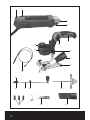
COMPONENT LIST
1. On/off switch lever
2. Variable speed dial
3. Chuck nut
4. Spindle lock button
5. Easy-grip control handle
6. Control handle locking screw
7. Dust extraction adaptor
8. Depth gauge locking screw
9. Base plate
10. Guide stop locking screw
11. Base of depth gauge
12. Fixing screw for main body
13. Soft shaft
14. Guide stop
15. Internal mounting disc
16. External mounting disc
17. Circular cutter
18. Pivot locking screw
19. Chuck
20. Spanner
21. Dust extraction tube
Not all the accessories illustrated or described are included in standard delivery.
ACCESSORIES
Guide stop 1
Soft shaft 1
Circular cutter 1
Dust extraction tube 1
Spanner 1
282 pcs tool kit in plastic box 1
We recommend that you purchase your accessories from the same store that sold you the tool. Refer to the
accessory packaging for further details. Store personnel can assist you and offer advice.
TECHNICAL DATA
Rated voltage 220-240V~50Hz
Rated power 550W
Rated speed
5000-25000/min
Collet size
1/4” ( 6. 3 5 m m )
Protection class /II
Machine weight 1.66k g

6
OPERATION INSTRUCTIONS
NOTE: Before using the tool, read the instruction book
carefully.
ASSEMBLY
WARNING: Before doing any assembly, switch the
tool off and unplug it from the power supply.
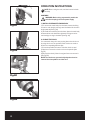
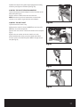
1. INSTALL OR REMOVE THE MAIN BODY
1) To remove the main body from the base, loosen the fixing
screw for main body by turning it anti-clockwise. Lift the main
body upwards. (See Fig. A1)
2) To install the main body onto the base, place the main body
downwards into the base hole, tighten the fixing screw for
main body by turning it clockwise. (See Fig. A2)
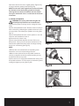
2. CHANGE THE CHUCK
You can attach the multi rotary cutting bits to the chuck nut
by using the chuck. The provided 3-size chucks are used to
attach corresponding different bits.
1) Press the spindle lock button. Twist the chuck nut anti-
clockwise to remove the chuck nut from the spindle. (See
Fig. B1)
2) Remove the chuck (if there is any) and insert a new one in.
(See Fig. B2)
NOTE: The chucks are symmetrically shaped and can be
inserted into the spindle from either end.
Fig.A1
Fig.A2
Fig.B1
Fig.B2
Fig.C2
Fig.C1
Fig.B3
Fig.C4
Fig.C3

7
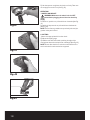
3) Re-insert the chuck nut into original position. Tighten it by
turning it clockwise gently by hand. (See Fig. B3)
NOTE: If no bit in the chuck, tighten the chuck nut will make
the diameter of the chuck opening smaller. It will make
inserting bits into chuck more difficult next time. Please
store your chucks with a bit in, or make sure the chuck nut
is left loose.
3. ATTACH CUTTING BITS
WARNING! The cutting and woodcarving bits are
extremely sharp. Please be care to handle them.
1) Remove the plastic covering from the cutting bit if there
is any.
2) Press the spindle lock button. Twist the chuck nut until you
hear a click which is indicating the spindle lock button is in its
correct position. This will stop the spindle from turning. (See
Fig. C1)
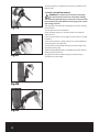
3) Press the spindle lock button, use the spanner to turn the
chuck nut anti-clockwise to loosen it.
4) Remove the bit if there is any.
5) Insert a new bit all the way into the chuck. Pull it out a
little (around 1-3mm) in order to leave a small amount of air
between the spindle and the bit, which can help preventing
the bit from overheating. (See Fig. C2)
NOTE:
• Different bits are matched with corresponding chuck.
Choose the correct chuck according to the bits.
• Make sure the spirals of bits are fully visible outside the
chuck. If you tighten the chuck around the spirals, you may
break the bit and injure yourself.
6) After the bit is correctly positioned inside the chuck, press
the spindle lock button. Turn the chuck nut clockwise by hand,
making it as tight as you can. (See Fig. C3)
Fig.A1
Fig.A2
Fig.B1
Fig.B2
Fig.C2
Fig.C1
Fig.B3
Fig.C4
Fig.C3

8
7) Use the spanner to tighten the chuck nut clockwise firmly.
(See Fig. C4)
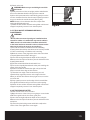
4. ADJUST THE CONTROL HANDLE
WARNING: It is important to hold the tool by using
the control handle, as the tool moves when cutting
and could otherwise pull away or stray over to the left. Hold
the tool with both hands will also afford you greater control
and cutting precision.
The easy-grip control handle is adjustable to suit the working
environment. •
You can place the control handle in:
• the horizontal position to use the tool like a normal back-
and-forth saw;
• the vertical position or at an angle to use the tool for cutting
freehand;
• the reverse position, it will provide a more comfortable and
practical grip for the hand task.
1) Loosen the control handle locking screw by turning it anti-
clockwise. (See Fig. D1)
2) Move the handle upwards or downwards into the desired
position. (See Fig. D2, D3)
3) Tighten the control handle locking screw by turning it
clockwise to fix the handle.
Fig.A1
Fig.A2
Fig.B1
Fig.B2
Fig.C2
Fig.C1
Fig.B3
Fig.C4
Fig.C3
a
Fig.D1
Fig.D2
Fig.D3
Fig.E1
Fig.F2
Fig.F1
Fig.E2
Fig.F4
Fig.F3

9
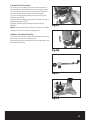
5. ADJUST THE DEPTH GAUGE
The cutting bit must always protrude from the base of the
depth gauge 4mm plus the thickness of the cutting material.
i.e. if the cutting material is 10mm thick, then the bit should
protrude 14mm beneath the base of the depth gauge.
1) Loosen the depth gauge locking screw by turning it anti-
clockwise. (See Fig. E1)
2) Slide the base of depth gauge upwards or down wards to a
desired depth. (See Fig. E2)
3) Tighten the depth gauge locking screw by turning it
clockwise.
NOTE: Check the depth of the bit before starting to cut. Make
sure the bit and the chuck are firmly tightened.
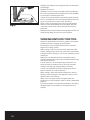
6. INSTALL THE CIRCULAR CUTTER
1) Unscrew the internal mounting disc and external mounting
disc from the circular cutter. (See Fig. F1)
2) Place the internal mounting disc onto the middle hole of the
base plate. (See Fig. F2)
a
Fig.D1
Fig.D2
Fig.D3
Fig.E1
Fig.F2
Fig.F1
Fig.E2
Fig.F4
Fig.F3

10
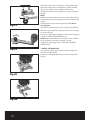
3) Position the internal mounting disc, mounting hole (a) and
external mounting disc in a straight line as shown in below
figure. Press the three parts together. (See Fig. F3)
4) Tighten the external mounting disc by turning it clockwise
by hand.
NOTE:
• Make sure the protruding section of the external mounting
disc passed through the mounting hole and is fastened firmly
in place.
• Only tighten the external mounting disc by hand. Do not
over-tightened.
5) Loosen the pivot locking screw by turning it anti-clockwise.
Slide the screw to adjust the radius of the circle you are going
to cut. (See Fig. F4)
6) Insert the appropriate cutting bit into the chuck and tighten
it. Refer to ATTACH CUTTING BITS section.
NOTE: Measure the distance from the pivot to the outside of
the bit to check if the radius is adjusted correctly.
7) Adjust the depth gauge. Refer to ADJUST THE DEPTH
GAUGE section.
7. INSTALL THE GUIDE STOP
1) Loosen the 2 guide stop locking screws by turning them
anti-clockwise. (See Fig.G1)
2) Insert the adjustable guide stop into the base plate. (See
Fig. G2)
a
Fig.D1
Fig.D2
Fig.D3
Fig.E1
Fig.F2
Fig.F1
Fig.E2
Fig.F4
Fig.F3
Fig.G1
Fig.G2
Fig.G3
Fig.H
Fig.I3
Fig.I2
Fig.I1
Fig.J2
Fig.J1

11
3) Adjust the depth of the guide stop and tighten the locking
screws by turning them clockwise. (See Fig. G3)
8. INSTALL THE DUST EXTRACTION ADAPTOR
1) Insert the dust extraction adaptor into the back hole of the
base plate. (See Fig. H)
2) Insert vacuum cleaner hose into the connector.
NOTE: If the size of your hose’ nozzle does not match the
connector, use a piece of garden hose as an adaptor.
9. INSTALL THE SOFT SHAFT
1) Remove the bit if there is any.
2) Remove the chuck if it is not the Ø6.35mm one. Insert the
Ø6.35mm chuck into the spindle.
3) Insert the rear section of the soft shaft into the chuck. (See
Fig. I1)
4) After the rear section of the soft shaft is correctly
positioned inside the chuck, press the spindle lock button,
turn the chuck nut clockwise by hand. Make it as tight as you
can. (See Fig. I2)
Fig.G1
Fig.G2
Fig.G3
Fig.H
Fig.I3
Fig.I2
Fig.I1
Fig.J2
Fig.J1

12
5) Use the spanner to tighten the chuck nut firmly. Take care
not to apply too much force. (See Fig. I3)
OPERATION
1. SWITCH ON AND OFF
WARNING: Make sure the switch is in the “OFF”
status before plugging the tool into the electricity
supply.
To switch on, push the on/off switch lever forwards (See Fig.
J1)
To switch off, depress the on/off switch lever backwards.
(See Fig. J2)
NOTE: This tool has a gradual start-up switch (soft start) for
greater safety and control.
2. CUTTING
1) Insert the appropriate bit into the chuck.
2) Adjust the depth gauge.
3) Hold the tool with both hands, position the edge of the
cutting base above the workpiece at a 45°angle. (See Fig. K1)
NOTE: Do not allow the bit to touch the material before the
tool is switched on and reaches its top speed.
Fig.G1
Fig.G2
Fig.G3
Fig.H
Fig.I3
Fig.I2
Fig.I1
Fig.J2
Fig.J1
Fig.K1
Fig.K2
Fig.L

13
4) Switch on the tool.
WARNING: Make sure you are holding the tool with
both hands.
5) Slowly move the tool into an upright position and allow the
bit to move downwards while cutting into the material.
6) After the bit penetrates the material fully, gently move the
tool in a clockwise direction. Use slow and constant pressure
as you cut and let the tool do the work. (See Fig. K2)
NOTE: Always cut in a clockwise direction, except when
cutting drywall/plasterboard.
7) Switch off the tool after finished cutting. Wait until the tool
stopped completely, remove it from the workpiece.
3. CUT PLUG SOCKET OPENINGS IN DRYWALL/
PLASTERBOARD
WARNING:
• Do not make cuts around openings or installations that
contain live cables or in walls which may contain cables in.
• Make sure the circuit breakers have been switched off
or the fuses have been removed in order to disconnect the
electrical circuit for the area you are working in.
1) Insert all the cables into back boxes before installing
drywall/plasterboard. Keep the cables as far back as possible
in order to avoid being cut while the tool is working.
2) Mark the center of the plug socket in the side of the sheet
of drywall/plasterboard that is facing you.
3) Insert the cutting bit, adjust the depth of the cutting bit.
Make sure the bit will protrude 4mm plus the thickness of the
drywall/plasterboard.
4) Hold the tool with both hands and switch it on.
5) Cut into the drywall/plasterboard at the point marking the
center of the plug socket.
6) Gentle move the bit towards the right until you feel and
hear it touch the inner edge of the back box.
7) Follow the inner edge of the box and move your tool
upwards. Keep a gentle pressure on the edge of the box.
When you feel the bit reaches the top-right corner, move the
tool to the left.
8) Keep a gentle pressure on the edge of the box and follow
the edge anti-clockwise until you have cut out the opening.
9) Switch off the tool after finished cutting. Wait until the tool
stopped completely, remove it from the workpiece.
4. USE THE CIRCULAR CUTTER
Use the circular cutter to cut circulars.
1) Mark the center of the circle you are going to cut and make
a Ø4.76mm guide hole for the center guide pivot.
2) Insert the cutting bit, adjust the depth of the cutting bit.
Make sure the bit will protrude 4mm plus the thickness of the
workpiece.
3) Loosen the pivot locking screw and slide it to adjust the
radius of the circle, tighten the screw again.
Fig.K1
Fig.K2
Fig.L

14
4) Position the edge of the cutting base above the workpiece
at a 45°angle.
5) Switch on the tool.
6) Slowly move the tool into an upright position and allow the
bit to move downwards while cutting into the material. Make
sure the pivot is inside the guide hole.
7) After the bit penetrates the material fully, gently move the
tool in a clockwise direction. Use slow and constant pressure
as you cut and let the tool do the work. (See Fig. L)
8) Cut out the circle, keeping the tool in an upright position
and the control handle flat above the workpiece. Carefully
rotate the circular cutter and the tool around the center
guide pivot.
9) Switch off the tool after finished cutting. Wait until the tool
stopped completely, remove it from the workpiece.
WORKING HINTS FOR YOUR TOOL
Always use both hands on the tool for greater control and to
prevent the bit from dropping off the workpiece.
The thickness of the workpiece should never exceed the
length of the cutting grooves.
When cutting a hole in a vertical surface, always start and
end the cutting process at the top of the hole, not the bottom.
It will prevent the material you cut out from fall away from the
rotating bit.
Always cut in a clockwise direction except when cutting
drywall/plasterboard. Cutting in anti-clockwise direction may
lose control of the tool.
You can use the 1/4” wood and multi-purpose bit to cut
wood up to 20mm thickness. Do not force the tool while
cutting. It can help to prolong the lifetime of the bits.
You can use the smaller wood and multi-purpose bits for
thinner materials, up to 8mm thickness.
When cutting in wood, there will be a slight pull to the left
because of the rotating bit. If you apply too much force, the
deviation will be more obvious.
When you are using the tool to carve glass, place the
workpiece on a sack of wheat in order to obtain a stable work
platform.
If the tool overheats, it may stop automatically to avoid being
damaged. Allow it to cool down for 30 minutes before re-
starting.
Fig.K1
Fig.K2
Fig.L

15
MAINTENANCE
Remove the plug from the socket before carrying
out any adjustment, servicing or maintenance.
Your power tool requires no additional lubrication.
There are no user serviceable parts in your
power tool. Never use water, chemical cleaners
or flammable substance or liquids to clean your
power tool. Wipe with a dry clean cloth to remove
dirt, oil and grease, etc. Always store your power
tool in a dry, safe place. Keep the motor ventilation
slots clean. Keep all working controls free of dust.
Frequently remove dust and accumulate debris using
a soft, DRY brush. Occasionally you may see sparks
through the ventilation slots. This is normal and will
not damage your power tool.
If the supply cord is damaged, it must be replaced
by the manufacturer, its service agent or similarly
qualified persons in order to avoid a hazard.
Only use identical spare parts when performing
maintenance work. Using other parts may cause a
hazard or damage the tool.
Do not attempt to modify the tool or make your own
accessories. It will cause injury to yourself. It will also
invalidate the warranty.
WARRANTY
This product is warranted for a 2-year period for
home domestic use from the date of the original
purchase. If found to be defective in materials
or workmanship, the tool or the offending faulty
component will be replaced free of charge with
another of the same item. A small freight charge
may apply.
The battery and charger only have a 1 year
manufacturer’s warranty.
The warranty replacement unit is only made
available by returning the tool to the place of
purchase with a confirmed register receipt.
Proof of purchase is essential.
We reserve the right to reject any claim where
the purchase cannot be verified.
This warranty does not include damage or defects
to the tool caused by or resulting from abuse,
accidents, alterations or commercial or business use.

-
 1
1
-
 2
2
-
 3
3
-
 4
4
-
 5
5
-
 6
6
-
 7
7
-
 8
8
-
 9
9
-
 10
10
-
 11
11
-
 12
12
-
 13
13
-
 14
14
-
 15
15
-
 16
16


jobmate JMPRT550.1 Safety And Operating Manual
- Category
- Power tools
- Type
- Safety And Operating Manual
Ask a question and I''ll find the answer in the document
Finding information in a document is now easier with AI