Eyevision DT-RLC Two Wire Video Intercom System Accessories User manual
- Category
- Door intercom systems
- Type
- User manual

Second Lock Release Module
DT-RLC-V01.01
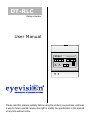
DT-RLC
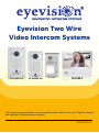
Eyevision Two Wire Video
Intercom Systems Accessories

DT-RLC
Relay actuator
Please read this manual carefully before using the product you purchase, and keep
it well for future use.We reserve the right to modify the specification in this manual
at any time without notice.
GND NO COM
2-WIRE SYSTEM
DT-RLC
NC 12V S2 S1 GND
POWER IN-USE BUS BUS RISER
1
2
3
User Manual

2. Parts and Name
DIP
1 2 3
12 3
ON
lock Control
Jumper
1
2
3
GND
NO
COM
NC 12V
S2
S1
GND
POWER
IN-USE
BUS
DIP
GND NO COM
2-WIRE SYSTEM
DT-RLC
NC 12V S2 S1 GND
POWER IN-USE BUS BUS RISER
1
2
3
-1-
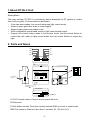
The relay actuator DT-RLC is a accessory device designed for DT system to control
door locks or lights. It has the features as follows:
•It has two work modes: lock control mode and light control mode;
•Allows to open gate door locks or control lights;
•Support high power-consumption lock;
•With configurable unlock timed output or light control timed output;
•Support exit control button: when in lock control mode, the exit control button to
control the lock; when in light control mode, the exit control button to control the
light.
1.About DT-RLC Unit
Description:
+12V:12V power output. Can be used to power the lock.
S2:Reserved.
S1:Exit button contact. Short this contact and the GND to unlock or control light.
GND:The common Ground of the other 3 contacts: S1, S2 and +12V.

-2-
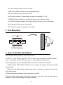
3. Unit Mounting
GND NO COM
2-WIRE SYSTEM
DT-RLC
NC 12V S2 S1 GND
POWER IN-USE BUS BUS RISER
1
2
3
DIN Rail Mounting
4. How To Set The Work Mode
Note that the factory default is lock control mode.
1).In DIP1 = ON, DIP2 = ON, DIP3 = OFF status, exit button(S1 and GND) short-
circuit, meanwhile, the DT-RLC will power-on to activate the setting mode;
2).In setting status, struck repeatedly DIP1 four times to switch work modes:
A.When the IN-USE indicator flashes once, it means the system will enter the light
control mode.
B.When the IN-USE indicator flashes two times, it means the system will enter the
lock control mode.
3).When the setting complete,it will automatically restart.
Please note the setting state valid within 5 seconds, more than five seconds without
operation, it will exit the setting mode automatically.
NC:The normally-closed contact to COM.
COM: The common contact of the unlock/light relay.
NO: The normally-open contact to COM.
Lock Control Jumper: To select the lock type: see section 5.3, 5.4.
POWER:Working indicator, it will light up when plugs in power supply.
IN-USE:Unlock/light indicator, it will light up when unlock(or turn on the light).
Bus:Connect to the bus line, no polarity.
DIP :Used for setting the address of the RLC.

DIP Bit State Descriptions
OFF,OFF,OFF Applies to door station1 & lock 1
OFF,OFF,ON Applies to door station1 & lock 2
ON,OFF,OFF Applies to door station2 & lock 1
ON,OFF,ON Applies to door station2 & lock 2
OFF,ON,OFF Applies to door station3 & lock 1
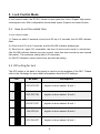
5.1 How to set the unlock time
-3-
5. Lock Control Mode
1). Power-on within 5 seconds, short-circuit S2 up to 3 seconds, the IN-USE indicator
flash.
2). Short-circuit S1 up to 3 seconds, and the IN-USE indicator always light.
3). Short-circuit again S2, meanwhile, the time of short-circuit equal to unlock time.
(the IN-USE indicator flashes once per second, Less than two seconds by one second
calculation; The maximum setting time is 30 seconds.)
4). After S2 released, saved unlock time, and exit the setting.
5.2 DIP setting for lock
The DIP switch in the back of the panel is used to set the address of the RLC. Please
refer to the followings for more detail informations about the DIP settings:
12 3
ON
12 3
ON
12 3
ON
12 3
ON
12 3
ON
In lock control mode, the DT-RLC allows to open gate door locks; Support high power-
consumption lock; With configurable unlock timed output; Support exit control button.
In lock control mode:

-4-
DIP Bit State Descriptions
OFF,ON,ON Applies to door station3 & lock 2
ON,ON,OFF Applies to door station4 & lock 1
ON,ON,ON Applies to door station4 & lock 2
12 3
ON
12 3
ON
12 3
ON
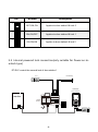
5.3 Internal powered lock connection(only suitable for Power-on-to-
unlock type)
Exit Button
GNDS1S2
NC 12V
COMNOGND
E-lock
monitor
-
+
L1 L2 PL S+ S-
1# Camera
(Device Address:0)
NO
POWER IN-USE BUS
GND COM
DT-RLC 2-WIRE SYSTEM
NC 12V S2 S1 GND
BUS RISER
1
2
3
-
+
DPS(V2)HDR-30-24
DT-RLC control the second lock of door station 1
12 3
ON
DIP

-5-
Note:
1. When DT-RLC connect Electronic
lock, the jumper position in 1-2.
2. When DT-RLC connect E-magnetic
lock, the jumper position in 2-3.
Jumper position in 1-2
1 2 3
GNDS1S2
NC 12V
COMNOGND
E-lock Exit Button
*
DT-RLC
+
-
DT-RLC connect lock
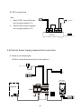
5.4 External Power Supply powered lock connection
Exit Button
GNDS1S212V
NCCOMNOGND
monitor
-
+
L1 L2 PL S+ S-
adaptor for the lock
E-lock
1# Camera
(Device Address:0)
-
+
NO
POWER IN-USE BUS
GND COM NC
DT-RLC 2-WIRE SYSTEM
12V S2 S1 GND
BUS RISER
1
2
3
DPS(V2)HDR-30-24
A. Power-on-to-unlock type:
12 3
ON
DIP
DT-RLC control the second lock of door station 1

-6-
Jumper position in 1-2
1 2 3
GNDS1S2
NC 12V
COMNOGND
E-lock Exit Button
*
POWER
SUPPLY
DT-RLC
+
-
Note:
1. Here's lock type is
Electronic lock.
DT-RLC connect lock
Exit Button
GNDS1S2
NC 12V
COMNOGND
monitor
-
+
L1 L2 PL S+ S-
adaptor for the lock
EM-lock
1# Camera
(Device Address:0)
NO
POWER IN-USE BUS
GND COM
DT-RLC 2-WIRE SYSTEM
NC 12V S2 S1 GND
BUS RISER
1
2
3
-
+
DPS(V2)HDR-30-24
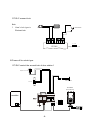
B.Power-off-to-unlock type:
12 3
ON
DIP
DT-RLC control the second lock of door station 1

-7-
Jumper position in 2-3
1 2 3
GNDS1S2
NC 12V
COMNOGND
EM- LOCK Exit Button
*
POWER
SUPPLY
DT-RLC
+
-
Note:
1. Here's lock type is
E-magnetic lock.
DT-RLC connect lock
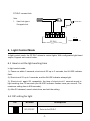
6.1 How to set the light working time
In light control mode:
1). Power-on within 5 seconds, short-circuit S2 up to 3 seconds, the IN-USE indicator
flash.
2). Short-circuit S1 up to 3 seconds, and the IN-USE indicator always light.
3). Short-circuit again S2, meanwhile, the time of short-circuit 1 seconds equal to
light working time 30 seconds.(the IN-USE indicator flashes once per second; The
maximum setting time is 900 seconds.)
4). After S2 released, saved unlock time, and exit the setting.
DIP Bit State Descriptions
OFF,OFF,OFF Set to the first DT-RLC.
12 3
ON
6. Light Control Mode
In light control mode, the DT-RLC
6.2 DIP setting for light
allows to control lights; With configurable light timed
output; Support exit control button.

-8-
DIP Bit State Descriptions
OFF,OFF,ON Set to the second DT-RLC.
ON,OFF,OFF Set to the third DT-RLC.
ON,OFF,ON Set to the fourth DT-RLC.
OFF,ON,OFF Set to the fifth DT-RLC.
OFF,ON,ON Set to the sixth DT-RLC.
ON,ON,OFF Set to the seventh DT-RLC.
ON,ON,ON Set to the eighth DT-RLC.
12 3
ON
12 3
ON
12 3
ON
12 3
ON
12 3
ON
12 3
ON
12 3
ON
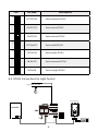
6.3 DT-RLC Connections for Light Control
110~250V AC Input
GNDS1S2
NC 12V
COMNOGND
monitor
-
+
L1 L2 PL S+ S-
(Device Address:0)
NO
POWER IN-USE BUS
GND COM
DT-RLC 2-WIRE SYSTEM
NC 12V S2 S1 GND
BUS RISER
1
2
3
DPS(V2)HDR-30-24
12 3
ON
DIP

-9-
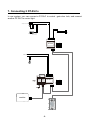
7. Connecting 2 DT-RLCs
110~250V AC Input
monitor
DT-RLC
POWER
GND
IN-USE
S1S2
NC 12V
COMNOGND
Exit Button
DT-RLC
POWER
GND
IN-USE
S1S2
NC 12V
COMNOGND
adaptor for the lock
E-lock
Safety Type: power-on to open
power-off to lock
DPS(V2)HDR-30-24
12 3
ON
DIP
12 3
ON
DIP
In one system, you can connect a DT-RLC to control gate door lock, and connect
another DT-RLC to control light.
(Device Address:0)
1 2 3
4 5 6
7 8 9
*0
#

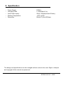
8. Specification
•Power Supply : DC24V;
•Unlocking Time: 1~30s(Default 1s);
•Lock Power supply: 12Vdc, 450mA(Internal Power);
•Working Temperature: 0 0
-10 C~+40 C;
•Dimension: 89(H)×71(W)×45(D)mm.
The design and specifications can be changed without notice to the user. Right to interpret
and copyright of this manual are preserved.
DT-RLC-V01.01 - 2022

Note

Note

Note

The design and specifications can be modified without notice to the user. Right to interpret
and copyright of this manual are reserved.
DT-RLC-V01.01
Eyevision Two Wire
Video Intercom Systems
EV-D298KP-SM
EV-D298KP-FM EV-2W-7
EV-D301
-
 1
1
-
 2
2
-
 3
3
-
 4
4
-
 5
5
-
 6
6
-
 7
7
-
 8
8
-
 9
9
-
 10
10
-
 11
11
-
 12
12
-
 13
13
-
 14
14
-
 15
15
-
 16
16


Eyevision DT-RLC Two Wire Video Intercom System Accessories User manual
- Category
- Door intercom systems
- Type
- User manual
Ask a question and I''ll find the answer in the document
Finding information in a document is now easier with AI