Nothern Lights M150C12 User manual
- Category
- Power generators
- Type
- User manual
This manual is also suitable for

OM175C2
OPERATOR’S
MANUAL
OPERATOR’S
MANUAL
OM175C2
For Model:
M175C2

Diesel engine exhaust and some of its constituents
are known to the State of California to cause
cancer, birth defects, and other reproductive harm.
— CALIFORNIA —
Proposition 65 Warning:
Northern Lights
4420 14th Avenue N.W.
Seattle, WA 98107
Tel: (206) 789-3880
Fax: (206) 782-5455
Copyright ©2005 Alaska Diesel Electric, Inc.
All rights reserved. Northern Lights™, and
the Northern Lights logo are trademarks of
Alaska Diesel Electric, Inc.
Printed in U.S.A.
PART NO.: OM175C2 04/05

OM175C2 04-05
3
Read this operator's manual thoroughly before starting to operate your equipment.
This manual contains information you will need to run and service your new unit.
OPERATOR'S MANUAL
OM175C2 for Model
M175C2
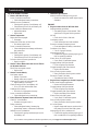
INTRODUCTION ................................................... 2
Models Included ................................................ 2
Model Numbers................................................. 2
Serial Numbers .................................................. 2
WARRANTY ........................................................... 3
SAFETY RULES .................................................... 3
COMPONENT LOCATIONS
M175C2............................................................. 4
ENGINE & GENERATOR CONTROL PANELS
Series 1, 3 & 4 ..............................................5 - 6
OPERATING PROCEDURES
Before Starting .................................................. 7
Shutdown Procedures ...................................7 - 8
Break-In Period ................................................. 8
SERVICING SCHEDULE CHART ...................... 9
SERVICE RECORD ............................................ 10
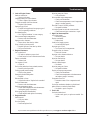
SERVICING
Lubrication - General ...................................... 11
Checking Oil ................................................... 11
Oil Changes ..................................................... 11
Changing Oil Filter.......................................... 11
Air Filter .......................................................... 11
Valve Clearances............................................. 12
Fuels - General ................................................ 13
Fuel Filters....................................................... 13
Crankshaft Damper ......................................... 14
Bleeding the Fuel System........................ 15 - 16
Injector Service ............................................... 16
Turbocharger ................................................... 17
Turbo Boost..................................................... 17
Cooling System - General ............................... 17
Engine Coolant Specifications ................ 18 - 19
Cooling System Flushing ................................ 19
Heat Exchanger Cleaning................................ 19
Zinc Anodes .................................................... 20
Raw Water Pump ............................................ 20
Generator Ends ................................................ 20
Electrical System - General............................. 20
Booster Batteries ............................................. 21
Battery Care..................................................... 21
Winterizing / Out-of-Service........................... 21
TROUBLESHOOTING
Electrical.......................................................... 22
Engine...................................................... 22 - 24
WIRING DIAGRAMS
AC Electrical ................................................... 25
DC Electrical ........................................... 26 - 27
ON-BOARD SPARE PARTS............................. 28
Proprietary Information
This publication is the property of Alaska Diesel Electric, Inc.
It may not be reproduced in whole or in part without the written permission of Alaska Diesel Electric, Inc.
© Alaska Diesel Electric, Inc. All rights reserved. Litho U.S.A. Publication number OM175C2 04/05
Table of Contents

OM175C2 04-05
4
Servicing of marine engines and generator sets presents
unique problems. In many cases boats cannot be moved
to a repair facility. Marine engines cannot be compared
to the servicing of automobiles, trucks or even farm
equipment. Failures often occur in remote areas far
from competent assistance. Marine engines are taxed
far more severely than auto or truck engines; therefore,
maintenance schedules must be adhered to more
strictly.
Failures begin with minor problems that are overlooked
and become amplified when not corrected during
routine maintenance.
As operator, it is your obligation to learn about your
equipment and its proper maintenance. This is not a
comprehensive technical service manual. Nor will it
make the reader into an expert mechanic. Its aim is to
aid you in maintaining your unit properly.
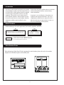
Introduction
M - Northern Lights marine generator set
Model number
6 Cylinders 8.1 Liters
Model Numbers
Model numbers give the unit's application, block model, aspiration, and RPM:
+
Northern Lights
®
turbocharged, 1800 RPM marine diesel
generator set with a John Deere 6081 Tier II engine block,
two valve with high pressure common rail.
M175C2
M
175
=
Serial Numbers
When referencing Alaska Diesel Electric equipment by serial number, please refer only to the number
stamped on the Northern Lights
®
serial number plate.
Serial Number Plates

OM175C2 04-05
5
CAUTION: This symbol is used throughout
this book to alert you to possible danger areas.
Please take special notice of these sections.
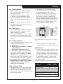
A warranty registration certificate is supplied
with your set. The extent of coverage is described
in the Limited Warranty Statement. We
recommend that you study the statement carefully.
NOTE: If the warranty is to apply, the servicing
instructions outlined in this manual must be
followed. If further information is needed, please
contact an authorized dealer or the factory..
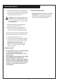
CAUTION:
Accident reports show that careless use of engines causes a high percentage of accidents.
You can avoid accidents by observing these safety rules. Study these rules carefully and enforce them on the job.
• Keep your hands, feet, hair and clothing away
from power-driven parts.
• Check for any loose electrical connections or
faulty wiring.
• Always disconnect ECU (Electronic Control
Unit) connectors and engine control system-to-
vessel ground before welding. High currents or
electro-static discharge in electronic
components from welding may cause permanent
damage.
• Engines should be operated only by
knowledgeable, qualified personnel.
• Look completely around engine to make sure
that everything is clear before starting.
• Do not operate an engine that isn't in proper
working order. If an unsafe operating condition is
noted, tag the set and control panel so others will
also know about the problem.
• Provide first aid kits.
• Never leave engine without proper security.
• Turn the coolant tank cap slowly to relieve
pressure before removing. Add coolant only
when the engine is stopped and cool.
• Mount a fire extinguisher near engine.
• Always disconnect the battery ground strap
before making adjustments.
• Operate engines in properly ventilated areas.
• Keep trash and other objects away from engine.
• Escaping fluids under pressure can penetrate
your skin. Use a piece of cardboard or wood,
not your hands, to search for leaks.
• Avoid wearing loose clothing when working
around engines.
• Do not oil or grease engine while it is running.
• Use caution in handling fuel. Never refuel a hot
or running engine. Do not smoke while filling
fuel tank or servicing fuel system.
Safety Rules
Warranty
CALIFORNIA
Proposition 65 Warning:
Diesel engine exhaust and some of its constituents
are known to the State of California to cause
cancer, birth defects, and other reproductive harm.

OM175C2 04-05
6
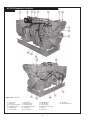
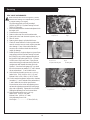
1. Junction Box
2. Air Cleaner
3. Secondary Fuel Filter
4. Primary Fuel Filter
5. Lube Oil Filter
6. Injection Pump
7. Coolant Fill
8. Expansion Tank
9. Heat Exchanger
10. Heat Exchanger Zincs
11. Belt Guard
12. Fuel Manifold
13. Lube Oil Drain
14. Lube Oil Fill
15. Turbocharger
16. Electronic Control Unit
17. Starter
18. Aftercooler
19. Alternator
20. Thermostat Cover
M175C2 Component Locations
Figure 1 & 2: M175C2

OM175C2 04-05
7
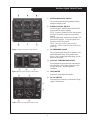
Northern Lights Control Panels
Figure 3: Series 3 Generator Control Panel
1. SHUTDOWN BYPASS SWITCH
This switch bypasses the safety shutdown feature
during the starting process.
2. ENGINE CONTROL SWITCH
To start the engine, hold this switch in the START
position until the engine is running.
NOTE: Excessive cranking of marine sets equipped
with water lift muffler systems can cause engine
damage.
After the engine starts, release the switch and it will
return to RUN position. To stop the engine, hold
the switch in the STOP position.
NOTE: The rocker switch is used on Series 1
panels only, and has a light that glows when the set
is running.
3. OIL PRESSURE GAUGE
The oil pressure gauge shows the oil pressure in the
engine lubricating system. If the pressure drops
below 15 PSI at a speed higher than idling, stop the
engine and investigate.
4. COOLANT TEMPERATURE GAUGE
Water temperature gauge shows the temperature of
the cooling water. If the gauge registers over 200°
or drops below 140°, stop the engine and
investigate.
5. HOUR METER
Keeps track of the engine running time.
6. DC VOLTMETER
When the engine is running, it indicates the voltage
output of the alternator.
Figure 4: Series 1-B Generator Control Panel
Figure 5: Series 3C Generator Control Panel

OM175C2 04-05
8
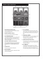
Figure 6: Series 4 Generator Control Panel
7. AC VOLTMETER
The voltmeter shows the generator output voltage,
phase to phase. If the voltage fluctuates greatly from
the normal reading, shut down the unit and investi-
gate.
8. FREQUENCY METER
Indicates engine speed. The correct reading for 1800
RPM sets is 60 Hz. If meter does not indicate
correct hertz, stop and investigate.
9. AMMETER SELECTOR SWITCH
The ammeter switch is used for checking each phase
for load condition. Leave it in the ON position while
the engine is running.
10. AC AMMETER
The ammeter indicates the phase load. Check for
load unbalance. If the unbalance is greater than 30%,
have an electrician balance the load properly. This
will ensure longer generator life and better economy.
1. SHUTDOWN BYPASS SWITCH
This switch bypasses the safety shutdown feature
during the starting process.
2. ENGINE CONTROL SWITCH
The control switch starts and stops the engine.
3. OIL PRESSURE GAUGE
The oil pressure gauge shows the oil pressure in the
engine lubricating system. If the pressure drops
below 15 PSI at a speed higher than idling, stop the
engine and investigate.
4. COOLANT TEMPERATURE GAUGE
Water temperature gauge shows the temperature of
the cooling water. If the gauge registers over 200°
or drops below 140°, stop the engine and investi-
gate.
5. HOUR METER
Keeps track of the engine running time.
6. DC VOLTMETER
When the engine is running, it indicates the voltage
output of the alternator.
Northern Lights Control Panel

OM175C2 04-05
9
Operating Procedures
BEFORE STARTING
1. Check the water level by removing the pressure
cap from the expansion tank. In order to give the
cooling water room to expand, the level should be
about 1 3/4 in. (4-5 cm) below the filler cap sealing
surface when the engine is cold. When filling with
coolant, the venting cock on top of the turbocharger
should be opened to ensure that no air pockets form
in the cooling system (see Service Point #12)
.
CAUTION: Use protective clothing and open
the filler cap carefully when the engine is warm
to prevent burns.
2. Check the oil level in the crankcase with the dipstick.
The oil level should be between the “waffled area”
and the “oo”. Never allow the level to go below the
“oo”. Always add the same viscosity of oil as is
already in the crankcase (see Service Point #1).
3. Check the fuel tank level and open any fuel valves.
4. Disengage clutch, if equipped.
5. Close the seacock, check and clean the strainer and
reopen the seacock.
6. Place the battery switch in the ON position.
NOTE: The battery switch must always be kept ON
while the engine is running. If the switch is turned
OFF while the engine is running, the battery charging
regulator could be ruined.
Starting
1. While holding the Shutdown Bypass switch in the
ON position, push the Engine Control switch to the
START position
2. As soon as the engine starts, release both switches.
Do not crank the starter for more than 20 seconds.
3. If the engine fails to start the first time, be sure the
starter has stopped for at least 2 minutes before
reengaging.
NOTE: If there is a governor locked at a specific
speed on the generator set, there may not be a slow
idle function, so in that case operate the engine at
high idle for 1 to 2 minutes before adding load. If the
stand-by generator set is loaded as soon as it
reaches rated speed, this procedure would not apply.
Operating
1. Check Gauges Often: Oil pressure must be above
29 PSI (if not above 15 PSI within 5 seconds of
starting, the engine should be stopped and the
problem should be explored.) Normal oil pressure is
50 PSI at rated load speed (1800 to 2500 RPM). The
DC voltmeter should read between 13 -14 volts (26 -
28 volts, 24 volt systems).
2. Check AC voltage and frequency meters (Series 4
Panel). If gauges deviate from normal levels, shut
down the set and investigate.
3. Check belt for good alignment.
4. Let the unit run unloaded for a three to five minute
warm-up period before applying load.
5. Do not add full electrical load until engine is at
maximum operating temperature.
Shutdown
1. Unload the generator and run for three to five
minutes for cool down period.
2. Turn the Engine Control Switch to the OFF position.
3. Close the sea cock and fuel valves, and put the
battery switch in the OFF position if the unit will be
off for an extended period.
NOTE: Do not turn the battery switch to OFF while
the engine is running.
SHUTDOWNS AND ALARMS
1. Your unit is fitted with a system to protect it from
high water temperature or low oil pressure.
a. Generator sets have shutdown systems to stop the
engine. They have no warning horns.
b. Other alarms and shutdowns are available as
optional equipment.
NOTE: Do not rely on your warning or shutdown
system to the exclusion of careful gauge monitoring.
Watching your gauges can prevent damage to the unit
and dangerous power losses.
2. Do the following when your shutdown system is
activated: (next page)

OM175C2 04-05
10
Operating Procedures
a. Check the temperature gauge. If the temperature is
above 205°F (97°C) shut off the engine immediately.
b. Use the Trouble Shooting Guide on pages 22- 24
to isolate the cause of the overheat.
CAUTION: Do not remove the water fill cap of an
overheated engine. Escaping high temperature
steam can cause severe burns. Allow the engine
to cool and then remove the cap slowly, using
protective clothing.
c. Make repairs and restart after the temperature
gauge registers below 180°F (83°C).
d. Watch the temperature gauge regularly and
turn off the unit if the temperature rises above
200°F (94°C). Repeat the troubleshooting process.
3. If the shutdown is activated and the temperature gauge
shows temperature within normal temperature range:
a. Check the engine crankcase oil level.
b.
If the oil level is low, fill with recommended lubricating
oil and restart. Watch the oil pressure gauge carefully
and shut off the engine if it does not show a normal
reading after a few seconds of operation.
c. If the oil level is normal, DO NOT restart the
engine. Call your Northern Lights or Lugger
dealer for assistance.
BREAK-IN PERIOD
1. The first 100 hours on a new or reconditioned engine
are critical to its life and performance.
2. Constantly check the engine temperature and oil
pressure gauges.
3. Oil consumption is greater during break-in as piston
rings and cylinder liners take time to seat.
4. Break-In Oil Changes: Change engine oil and filter
at 50 hours. Change oil and filter again at 100 hours
(See Gear Owner's Manual for break-in oil change
procedures. Consult Lubricants Section for oil
recommendation).
OPERATING INSTRUCTIONS
Maintain at least a 75% load on your set for the
first 100 hours.
If this is not possible, maintain no
less than a 50% load to ensure proper seating of the
piston rings. Vary the load to help seat rings.

OM175C2 04-05
11
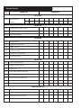
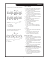
Servicing Schedule Chart
The Servicing Schedule Chart below shows the service schedule required for proper maintenance of your marine engine
or generator set. More detailed coverage of each Service Point (SP) is listed on the page noted in the ‘page’ column.
DAILY:
SP1 Check oil level in engine
SP8 Check primary fuel filter
SP15 Check cooling water level
AFTER FIRST 50 HOURS:
SP2 Change engine oil
SP3 Change lube oil filter
EVERY 50 HOURS:
SP21 Check electrolyte in batteries
AFTER FIRST 100 HOURS/ EVERY TWO WEEKS
5
:
SP2 Change engine oil after first 100 hrs., then check every 2 wks.
SP3 Change oil filter after first 100 hrs., then check every 2 wks.
SP4 Check air cleaner valve & restriction indicator gauge
6
SP7 Check crankshaft vibration damper
7
SP15 Check coolant level
EVERY 250 HOURS:
SP2 Change engine oil & filters (fuel filter/water bowl)
SP4 Replace air cleaner
SP5 Check V-belt condition
SP9 Change primary filter element (Racor)
SP25 Check engine mounts
EVERY 500 HOURS / YEARLY:
SP7 Check crankshaft vibration damper
SP10 Change secondary fuel filter
SP11 Check injectors
SP14 Check turbocharger boost pressure
SP16 Check cooling system
SP20 Change impeller in raw water pump
SP22 Check the state of the charge of the batteries
SP26 Clean crankcase vent tube
SP27 Check air intake hoses
SP29 Check electrical ground connection
SP30 Check engine speeds
EVERY 2000 HOURS:
SP6 Check & adjust valve clearance
SP12 Check fuel injection pump
SP16 Flush cooling system
SP17 Check and clean heat exchanger
SP18 Check and clean gear oil cooler
SP23 Test thermostats
SP31 Adjust variable speed (droop)
1) Change the oil and filter before the first 100 hours of operation during engine
break-in.
2) Perform all maintenance once a year even if hour level has not been reached.
3) Consult manufacturer's maintenance schedule, note on chart.
4) Whenever necessary.
SERVICE 50 100 250 500 2000
POINT PAGE OPERATION DAILY Hours Hours Hours Hours Hours
ENGINE:
SP1 15 Check oil level ●●
SP2 15 Change engine oil 1) 2) ●●●
SP3 15 Change lube oil filters 1) 2) ●●●
SP4 15 Check air cleaner valve 2) 4) 6) ●
SP5 Check belt condition 2) ●
SP6 16 Check valve clearances 2) ●
SP7 17 Check crankshaft vibration damper 7) ●
SP25 Check engine mounts ●
SP27 Check air intake hoses ●
SP30 Check engine speeds ●
FUEL SYSTEM:
SP8 17 Check primary filter (Racor) 3) ●
SP9 17 Change primary filter element (Racor) 3) 4) ●
SP10 17 Change secondary fuel filter 2) 4) ●
SP11 Check injectors ●
SP12 Check fuel injection pump ●
TURBOCHARGER:
SP13 23
Check air, oil & cooling water lines for leakage
2)
●
SP14 23 Check boost pressure ●
COOLING SYSTEM:
SP15 25 Check cooling water level ●
SP16 25 Check cooling system, flush @ 2000 hrs. 2) ●●
SP17 25 Check and clean heat exchanger 2) ●
SP18 Check and clean gear oil cooler 2) ●
SP19 25-26 Check zinc electrodes 2) 4) ●
SP20 26 Change impeller in raw water pump 2) 4) ●
ELECTRICAL SYSTEM:
SP21 27 Check electrolyte level in batteries 2) 4) ●
SP22 27 Check condition of batteries with hydrometer 2) ●
SP23 Test thermostats ●
SP29 Check electrical ground connection ●
5) Operate engine at rated speed with 50-70% load for 30 minutes at
least.
6) Replace air cleaner element when restriction indicator shows
vacuum of 625 mm (25 in.) H
2
0.
7) Replace damper every 4500 hours or after 60 months.

OM175C2 04-05
12
Service
Point
HOURS/DATE
Service Record
OPERATION
50 HOURS
SP21 Check electrolyte
in batteries
100 HOURS
SP9 Change primary fuel filter element
SP13 Check turbocharger air, oil & cooling lines for leakage
SP19 Check zinc electrodes
250 HOURS
SP2 Change engine oil
SP3 Change lubricating oil filters
SP4 Replace air cleaner
SP5 Check belt condition
SP9 Change primary filter element
SP25 Check engine mounts
500 HOURS
SP7 Check crankshaft damper
SP10 Change secondary fuel filter
SP11 Check injectors
SP14 Check turbocharger boost pressure
SP16 Check cooling system
SP17 Check and clean heat exchanger
SP20 Change impeller in raw water pump
SP22 Check state of charge of batteries
EVERY 2000 HOURS
SP6 Check valve clearances / Test thermostats
SP12 Check fuel injection pump
SP18 Check and clean gear oil cooler
SP16 Flush cooling system

OM175C2 04-05
13
LUBRICATION
Break-in oil
1. Use one of the following during the first 100 hours
of operation:
a. John Deere Engine Break-In Oil
b. API Service CE oil
c. ACEA Specification E1
2. Do not use John Deere PLUS-50 oil or engine oils
meeting API CG4, API CF4, ACEA E3, or ACEA E2
performance levels during the first 100 hours of
operation of a new or rebuilt engine. These oils will
not allow the engine to break-in properly.
Lubrication - General
1. Use only clean, high quality lubricants stored in
clean containers in a protected area.
2. These oils are acceptable after the first 100 hours:
a. API Service CC/CD single viscosity oils.
b. API Service CD/CG-4/CF-4 multi-viscosity oils.
c. ACEA Specification E3/E2 multi-viscosity oils.
d. CCMC Specification D5 and Mercedes Benz
MB228.3.
e. CCMC Specification D4 and Mercedes Benz
MB228.1.
3. Use the proper weight oil for your average operation
temperature.
4. Some increase in oil consumption may be expected
when SAE 5W and SAE 5-20W oils are used. Check
oil level frequently.
5. Never put additives or flushing oil in crankcase.
SP1. CHECK ENGINE OIL LEVEL
1. Check the oil level in the crankcase, with the oil
dipstick, daily.
2. The oil level must be between the “Waffled area” and
the “oo”. Never allow the level to go below the “oo”.
3. Always add the same viscosity of oil as is already in
the crankcase.
a. Run engine 5 minutes to warm up oil, shut off
engine.
b. Remove plug from outlet in base frame. Screw in
owner-supplied drain hose.
c. Open valve at oil pan outlet. After oil has been
drained into suitable container, close valve, remove
drain hose and replace plug in base frame outlet.
d. Refill engine with recommended oil.
e. Crank engine for 30 seconds without letting
engine start. This will ensure lubrication of
engine components before engine starts.
f. Start engine and check for leaks. Stop engine and
check oil level after 10 minutes.
4. Engine Lube Oil Capacity:
SP3. CHANGING OIL FILTER
1. Change the lube oil filter every 250 hours.
2. Use a filter wrench to remove old filter. Dispose of filter
in approved manner.
3. Make sure the gasket from the old filter is removed and
discarded.
4. Lubricate the rubber gasket on the new filter and screw it
on nipple until gasket meet the sealing surface.
5.
Using hands only, no wrench, tighten filter one-half turn
farther. Overtightening can do damage to filter housing.
6. Fill engine with recommended oil. Start engine and
check for leakage. Stop engine and check oil level. Add
additional oil if necessary.
SP4. AIR CLEANER
1. Inspect air cleaner valve daily. Replace filter when
indicator show a vacuum of 625 mm (25 in.) H
2
0.
2. Clean the rubber tube at the cleaner. Loosen the hose
clamp and the attaching strip for the cleaner.
3. Make sure the rubber tube is in good condition and that
new filter is absolutely clean and installed properly.
4. Start the engine and check for leaks.
NOTE: Make absolutely sure no impurities enter the
engine while changing the element. Do not run the engine
with the air cleaner removed.
Air Single Multi
Temperature Viscosity Viscosity
Above 32°F
(0°C)
SAE-30W SAE15-40W
-10°F to 32°F
(-23°C to 0°C)
SAE-10W SAE10-30W
Below -10°F
(-23°C)
SAE-5W SAE5-20W
M175C2 30.1 qts. 28.5 liters
Servicing
SP2. OIL CHANGES
1. Using the oil recommended above, change the engine oil
and filter after the first 50 hours of operation, the first
100 hours and every 250 hours thereafter.
2. During intermittent cold weather operation, change oil
every 100 hours or six weeks, whichever comes first.
3. Change oil at any seasonal change in temperature when a
new viscosity of oil is required.

OM175C2 04-05
14
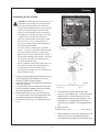
SP6. VALVE CLEARANCES
Caution: Always disconnect the negative (-) battery
terminal when making valve adjustments to prevent
accidental starting of the engine.
The following special tools will be needed:
JDE 820 or JDE 81-1 Flywheel Turning Tool and
JDE 81-4 Timing Pin.
1. Valve clearances must be checked and adjusted with
the engine cold.
2. Disconnect the wiring harness.
3. Remove rocker arm cover with ventilator tube.
4. Remove the wires from electronic injectors.
(Fig. 7B)
5. Take off carrier.
6. Remove plastic plugs in cylinder block bores.
7. Check all contact surfaces of valve tips and rocker
arms for excessive wear or cracks, replace parts that
show damage. If any of the rocker arms show
excessive valve clearance check them more thor-
oughly for damage.
7. Rotate flywheel in clockwise direction (viewed from
water pump) with the Flywheel Turning Tool until
the Timing Pin (Fig. 8A&B) engages timing hole in
the flywheel. Both rocker arms for No. 1 cylinder
will be loose at Top Dead Center. If they are not,
remove the timing pin and rotate the flywheel one
complete turn and reinstall the timing pin in the
flywheel. Use a bent feeler gauge (Fig. 9) to check
the valve clearances on numbers 1, 3, and 5 exhaust
valves and numbers 1, 2, and 4 intake valves.
9. Valve checking clearance (Rocker arm to valve tip):
Intake Valve: 0.016- 0.020 in. (0.41- 0.51 mm)
Exhaust Valve: 0.026- 0.030 in. (0.66- 0.76 mm)
10. If valves need to be adjusted, adjust valve clearance
on number 1, 3, and 5 exhaust valves and number 1,
2, and 4 intake valves to below specification.
Loosen the nut on the rocker arm adjusting screw
and turn the adjusting screw until the feeler gauge
slips with a slight drag. Tighten the lock nut while
holding the adjusting screw with a screwdriver.
11. Valve clearances (Rocker arm to valve tip):
Intake Valve: 0.018 in. (0.46 mm)
Exhaust Valve: 0.028 in. (0.71 mm)
Valve Adjusting Screw Lock
Nut Torque..............................27 N•m (20 lb-ft)
Servicing
RG7013
RG11559
Reproduced by permission of Deere & Company, c2005. Deere & Company.
All rights reserved. Fig. 9
Reproduced by permission of Deere & Company, c2005. Deere & Company.
All rights reserved. Fig. 8
A- Flywheel Turning Tool B- Timing Pin
RG12605
Reproduced by permission of Deere & Company, c2005. Deere & Company.
All rights reserved.
Fig. 7

OM175C2 04-05
15
FUELS - GENERAL
1. Use only clean, high quality fuels of the following
specifications, as defined by ASTM designation
D975 or EN590 for diesel fuels:
a. Use grade no. 2 diesel at ambient temperatures
above freezing 30°F (0°C).
b. Use grade No.1 at ambient temperatures below
freezing and for all temperatures at an altitude of
above 5,500 ft. (1500 meters).
2. Sulphur content should not exceed 0.5% (preferably
less than 0.05%).
3. The cetane number should be a minimum of 45.
Greater than 50 is preferred.
4. DO NOT use these unsuitable grades of fuel:
a. Domestic heating oils, all types.
b. Class B engine.
c. Class D domestic fuels.
d. Class E, F, G or H industrial or marine fuels.
e. ASTM-D975-60T No. 4-D and higher number
fuels.
f. JP4
5. Storing fuel:
a. Keep dirt, scale, water and other foreign matter
out of fuel.
b. Avoid storing fuel for long periods of time.
c. Fill the fuel tank at the end of each day's
operation. This will reduce condensation.
SP8-10. FUEL FILTERS
1. Your engine or generator set should have a primary
fuel filter installed. We recommend the Racor brand
of fuel filter - water separators.
a. Check the primary fuel filter daily as recommended
by the filter manufacturer. Empty the collection
bowl as necessary.
b. Change the element every 250 hours or whenever
necessary.
c. If the bowl fills with water, change the primary
and secondary elements immediately.
2. Change secondary fuel filter every 600 hours.
NOTE: The fuel filter on the engine is considered the
“secondary fuel filter”. The engine will be fitted with a
quick change disposable secondary fuel filter.
a. Turn off the fuel.
b. Open the filter drain plug and drain the filter
c. Remove the secondary fuel filter by turning the
filter clamp counter clockwise until the filter
cartridge slides out.
Servicing
Reproduced by permission of Deere & Company, c2005. Deere & Company.
All rights reserved.
Fig. 10
A - Front of Engine
B - No. 1 Cylinder “TDC”
C - No. 6 Cylinder “TDC”
After adjusting valves tighten rocker arm cover
capscrews in the order as shown below.
RG11569
RG11620
Reproduced by permission of Deere & Company, c2005. Deere & Company.
All rights reserved. Fig. 11
D - Front of Engine
Compression stroke at Top dead center shown below.

OM175C2 04-05
16
3. To check the vibration damper radial runout, place
the dial indicator touching the outer diameter of the
damper (Fig. 14). For dual dampers, check the
runout on the inner damper only (Fig. 15).
4. Make sure the engine is at operating temperature
then rotate the crankshaft using the JD820 Fly-
wheel turning tool.
5. If the runout reading exceeds the below specifica-
tion, replace the vibration damper.
Vibration Damper Maximum
Radial Runout..........................1.02 mm (0.040 in.)
RG7065
Reproduced by permission of Deere & Company, c2004. Deere & Company.
All rights reserved. Fig. 14
Position of dial for single damper
Reproduced by permission of Deere & Company, c2004. Deere & Company.
All rights reserved. Fig. 15
Position of dial for dual damper
RG7370
Servicing
NOTE: Before installing a new filter cartridge make sure
the surfaces where the cartridge comes in contact with the
mounting plate are absolutely clean. Dirt can be washed
into the fuel injection system. This may result in severe
damage to the fuel injection pump or nozzles.
d. Install new filter cartridge.
e. Fuel filter cartridge numbers are:
RE503676 Primary & RE506428 Secondary
f. Turn on the fuel.
SP 7. CHECKING CRANKSHAFT DAMPER
Note: Always replace two dampers as a set on units
equipped with dual dampers.
1. Remove belts.
2. Try to turn the vibration damper in both directions
while grasping it with both hands. If rotation can be
felt, the damper is defective and should be replaced.
Reproduced by permission of Deere & Company, c2005. Deere & Company.
All rights reserved. Single Damper Fig. 12
RG7208
RG7369
Reproduced by permission of Deere & Company, c2005. Deere & Company.
All rights reserved. Dual Damper Fig. 13
Note: The vibration damer assembly should be
replaced every 4500 hours or 60 months, whichever
occurs first, as the vibration damper assembly is not
repairable. Always replace the vibration damper
when the crankshaft is replaced or a major engine
overhaul takes place.

OM175C2 04-05
17
BLEEDING THE FUEL SYSTEM
CAUTION: Escaping diesel fuel under pressure can
penetrate the skin, causing serious personal injury.
Before disconnecting lines be sure to relieve all
pressure. Before applying pressure to the system be
sure all connections are tight and the lines, pipes
and hoses are not damaged. Fuel escaping from a
very small hole can be almost invisible. Use a piece
of cardboard or wood rather than the hands to
search for suspected leaks. If injured by escaping
fuel, see a doctor at once. Serious infection or
reaction can develop if proper medical treatment is
not administered immediately.
Do not disconnect or attempt repair of fuel lines,
sensors, or any other components between the high-
pressure fuel pump and nozzles on engines with
High Pressure Common Rail fuel systems as high
pressure fluid remaining in the fuel lines could cause
serious injury. Only technicians familiar with this
system should attempt repair.
Due to the High Pressure Common Rail system, the
fuel in the filter is likely to be under high pressure.
To relieve pressure (and avoid injury) prior to
removing filter, open valve
(Fig. 16 A)
on the bottom of
the water separator bowl.
1. Whenever the fuel system has been opened for service,
(lines disconnected, filter changed, etc.) it will be
necessary to bleed air from the system.
2. Fuel filters must be pre-filled whenever they are being
removed or replaced.
3. To properly drain water from the filter the drain valve
must be unthreaded completely and the valve should
drop down approximately 12 mm (0.5 in.).
4. Open the drain valve (Fig. 16-A) on the primary (Fig.
16-D) and secondary (16-E) filters and drain the water
and contaminates from the water separator bowl.
5. Pre-fill the fuel filters (Fig. 17-C) using the pre-fill cup
(17-B).
RG13269
Servicing
Reproduced by permission of Deere & Company, c2004. Deere & Company.
All rights reserved. Fig. 17
6. To bleed the fuel system, loosen the fuel outlet
(Fig. 18-A) on the transfer pump. Unlock and operate
hand primer (Fig. 18-B) until a steady flow of fuel
without bubbles comes out of the connection. This
could take 270 to 330 strokes until the fuel flow
comes out clear of bubbles. Then retighten the fuel
line.
Torque Specification:
Fuel Outlet Lines Torque............................24 N•m (18 lb-ft)
7. Operate hand primer (18-B) until a steady flow of fuel
comes out of the hose. Pump hand primer while
disconnecting JTO3472 coupler from diagnostic port.
RG13296
Reproduced by permission of Deere & Company, c2004. Deere & Company.
All rights reserved. Fig. 16

OM175C2 04-05
18
Servicing
Reproduced by permission of Deere & Company, c2004. Deere & Company.
All rights reserved. Fig. 18
8. Loosen the high-pressure fuel supply line (18-C)
and operate hand pump until a stream of fuel
without bubbles comes out. Tighten the high
pressure fuel supply line to the specification as
follows.
High Pressure Fuel Line Torque.................24 N•m (18
lb-ft)
9. Loosen one of the high-pressure fuel supply lines
(18-D) and use hand pump until steady stream of
fuel comes out. Tighten the high-pressure fuel
supply line to the above specification.
10. Loosen fuel line fitting on fuel rail flow limiter #6
(18-E). Use a rag to put around the fitting to absorb
excess fuel. Pump the hand primer fuel flows
steadily. Tighten the line back to above specifica-
tion.
11. Pump the hand primer about 30 more times and
then lock it by pulling up then pushing down.
12. Crank the engine no more than 15 seconds. If the
engine fails to start, wait another 15 seconds and
then crank for an additional 15 seconds. If it starts,
then run it at 1200 to 1500 RPM for 3 to 5 minutes.
If the engine still fails to start, loosen the fuel line
fitting on the High Pressure Common Rail flow
limiter (Fig. 18-E). Use a rag around the fitting to
absorb the fuel and pump the hand primer until a
steady flow of fuel comes out of the flow limiter.
Tighten the fuel lines to the specification below and
lock the hand primer by pulling up, then pushing
down on it to lock it.
High Pressure Fuel Line Torque................24 N•m
(18 lb-ft)
RG13270
P11. INJECTORS
1. Fuel injectors should be checked by a Northern
Lights dealer or qualified fuel injection shop every
500 hours.
IMPORTANT: Do not attempt to service
injection pump or fuel injectors yourself -
special training and tools are required. In
addition, modification or alteration of the
injection pump, fuel injectors, or the injection
pump timing in ways that are not recommended
by the manufacturer could terminate the
warranty. And tampering with the fuel system
that leads to alteration of emission related
equipment on the engine could result in fines or
other penalties per EPA regulations or other
local emission laws.

OM175C2 04-05
19
Servicing
SP12. TURBOCHARGER
1. Check for air leaks every 200 hours. Air leakage
will lower engine output and may cause black
exhaust smoke and soot.
2. Listen along air line while engine is running.
A whistling or hissing sound indicates leakage.
3. Leakage on the pressure side, between turbo and
engine, can be found by applying soapy water to the
air line.
4. Tighten the hose clamps, replace hose or gaskets as
required.
5. Check to see that the lubrication and cooling lines
are tight and without leaks.
SP13. TURBO BOOST
1. This check measures the amount of air the turbo is
pushing into the engine. It should be done by an
authorized dealer every 500 hours.
2. On the inlet manifold there is a 1/8" NPT threaded
port. Remove the plug and install the boost gauge
hose. Refer to your engine specifications for correct
pressure.
COOLING REQUIREMENTS
1. To meet cooling system protection requirements, the
coolant solution must consist of:
a. Quality water
b. Ethylene glycol concentrate (EGC ) commonly
known as antifreeze.
c. Supplemental coolant additives (SCA's).
2. A coolant solution of ethylene glycol concentrate
(EGC-antifreeze), quality water and supplemental
coolant additives (SCA's) MUST be used YEAR
ROUND to protect against freezing, boil-over, liner
erosion or pitting and to provide a stable, noncorro-
sive environment for cooling system components.
3. Ethylene glycol coolant concentrate (antifreeze)
normally DOES NOT contain the SCA chemical
inhibitors needed to control liner pitting or
erosion, rust, scale, and acidity.
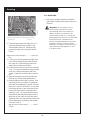
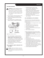
LINER EROSION (PITTING)
1. Cylinder liner walls
(Fig. 19-A) which are in contact
with engine coolant (19-B) can be eroded or pitted
unless the proper concentration and type of SCA's
are present in the coolant. Water pump impellers are
also susceptible to pitting.
2. Vapor bubbles (Fig. 19-C) are formed when the
piston's impact causes the liner walls to vibrate,
sending pressure waves into the coolant.
3. These tiny vapor bubbles collect on the surface
of metal parts. As the bubbles collapse (pop) a
microscopic piece of metal is eroded from the
metal part. Over a period of time, this pitting may
progress completely through the cylinder liner of a
wet-sleeve, heavy-duty diesel engine. This allows
coolant to enter the combustion chamber. Engine
failure or other serious damage will result.
A - Cylinder Liner Walls B - Engine Coolant C - Vapor Bubbles
Figure 19
4. Unprotected engines with low quality water as
coolant can have liner failure in as few as 500 hours.
WATER QUALITY
1. Distilled, deionized, soft water is preferred for use in
cooling systems. Bottled distilled water from a food
store or water supplier is recommended. Tap water
often has a high mineral content. Tap water should
NEVER be put in a cooling system unless first tested
by a water quality laboratory. Do not use water
made by the reverse osmosis method unless it has
been PH neutralized.
2. Here are acceptable water quality specifications:
Parts Grains
Contaminates per Million per Gallon
Maximum Chlorides 40 2.5
Maximum Sulfates 100 5.9
Maximum Dissolved Solids 340 20.0
Maximum Total Hardness 170 10.0
PH Level 5.5 to 9.0

OM175C2 04-05
20
3. If chlorides, sulfates or total dissolved solids are
higher than the above given specification, the water
must be distilled, demineralized, or deionized before
it is used in a cooling system.
4. If total hardness is higher than 170 ppm and all other
parameters are within the given specifications, the
water must be softened before it is used to make
coolant solution.
EGC: ETHYLENE GLYCOL CONCENTRATE
(ANTIFREEZE)
CAUTION: EGC (Antifreeze) is flammable.
Keep it away from any open flame. Avoid contact
with eyes. Avoid contact with skin. Do not take
internally. In case of contact, immediately wash
skin with soap and water. For eyes, flush with
large amounts of water for at least 15 minutes.
Call a physician. KEEP OUT OF REACH OF
CHILDREN.
Follow all warnings on the container.
1. Ethylene glycol coolant concentrate is commonly
mixed with water to produce an engine coolant with
a low freeze point and high boiling point.
2. A low silicate form of ethylene glycol coolant is
recommended for all diesel engines.
3. Use an ethylene glycol coolant concentrate
meeting ASTM D 4985P, SAEJ1941, General
Motors Performance Specification GM1899M,
or formulated to GM6038M.
4. This product is concentrated and should be mixed
to the following specification.
5. If additional coolant solution needs to be added
to the engine due to leaks or loss, the glycol
concentration should be checked with a hydrometer
to assure that the desired freeze point is maintained.
IMPORTANT
1. DO NOT use methyl alcohol or methoxy propanol
base EGC. These concentrates are not compatible
with chemicals used in supplemental coolant
additives. Damage can occur to rubber seals on
cylinder liners which are in contact with coolant.
2. DO NOT use an EGC containing sealer or stop-leak
additives.
3. DO NOT use EGC containing more than 0.1%
anhydrous metasilicate. This type of concentrate,
which is intended for use in aluminum engines, may
cause a gel-like deposit to form that reduces heat
transfer and coolant flow. Check container label or
consult with supplier.
SUPPLEMENTAL COOLANT ADDITIVE (SCA)
CAUTION: Supplemental coolant additive
contains alkali. Avoid contact with eyes. Avoid
contact with skin. Do not take internally. In case of
contact immediately wash skin with soap and
water. For eyes, flush with large amounts of water
for at least 15 minutes. Call a physician. KEEP
OUT OF REACH OF CHILDREN. Follow all
warnings on the container.
1. Important heat exchanger cooled engines
Additional SCA's should NOT be added to the
mixture of EGC/H
2
0 on initial fill up of engines
with a coolant conditioner-filter. A high SCA
concentration will result and can cause
silicate-dropout. When this happens, a gel-type
deposit is created in the cooling system which
retards heat transfer and coolant flow.
2. If additional SCA's are needed, prepare a mixture
of 50% quality water and 50%EGC (antifreeze).
Add liquid SCA at a rate of 3%, by volume.
Example: 30 mL of SCA per liter of H
2
O/EGC
mixture (1.0 fl oz of SCA per qt of H
2
O/EGC).
Add the resulting mixture to the cooling system in
quart increments. Run the engine for 2 hours and
retest the coolant. Continue process until SCA
concentration meets recommended levels.
3. SCA is available from your Northern Lights dealer
in the following sizes.
Pint - Part Number...............20-00002
1/2 gallon - Part Number.....20-00003
4. DO NOT use any coolant system additives
containing soluble oil.
Distilled EGC % Freeze Boiling
Water % Antifreeze Point Point
Optimum 50% 50%
-37°C +109°C
-34°F +226°F
Minimum 60% 40%
-24°C +106°C
-12°F +222°F
Maximum 40% 60%
-52°C +111°C
-62°F +232°F
Servicing
Page is loading ...
Page is loading ...
Page is loading ...
Page is loading ...
Page is loading ...
Page is loading ...
Page is loading ...
Page is loading ...
-
 1
1
-
 2
2
-
 3
3
-
 4
4
-
 5
5
-
 6
6
-
 7
7
-
 8
8
-
 9
9
-
 10
10
-
 11
11
-
 12
12
-
 13
13
-
 14
14
-
 15
15
-
 16
16
-
 17
17
-
 18
18
-
 19
19
-
 20
20
-
 21
21
-
 22
22
-
 23
23
-
 24
24
-
 25
25
-
 26
26
-
 27
27
-
 28
28


Nothern Lights M150C12 User manual
- Category
- Power generators
- Type
- User manual
- This manual is also suitable for
Ask a question and I''ll find the answer in the document
Finding information in a document is now easier with AI
Related papers
-
Nothern Lights M20CR2 User manual
-
-
-
-
-
-
-
-
-
Other documents
-
 Lugger L1276A User manual
-
 Lugger L844D User manual
-
 Lugger L944D User manual
-
 Northern Lights Lugger M843NW3 User manual
-
 Northern Lights Lugger M773LW3 User manual
-
 Lugger L6125 User manual
-
 Lugger L1066H User manual
-
 Lugger L1066A User manual
-
Doosan DE12T Operation & Maintenance Manual
-
 Northern Lights Lugger M773LW3 User manual


