Page is loading ...

INSTALLATION & OPERATION MANUAL
FOR JACKSON MODELS:
JPX-300H
JPX-300HC
JPX-300HN
JPX-300L
Jackson MSC Inc.
P.O. BOX 1060
HWY. 25E
BARBOURVILLE, KY. 40906
PHONE (606) 523-9795
FAX (606) 523-9196
www.jacksonmsc.com
An Company
JPX-300 UNDERCOUNTER DISHMACHINE SERIES
March 06, 2007
P/N 7610-002-71-26 (Revision J)

ALL NEW JACKSON DISHWASHERS ARE WARRANTED TO THE ORIGINAL PURCHASER TO BE FREE FROM
DEFECTS IN MATERIAL OR WORKMANSHIP, UNDER NORMAL USE AND OPERATION FOR A PERIOD OF (1) ONE
YEAR FROM THE DATE OF PURCHASE, BUT IN NO EVENT TO EXCEED (18) EIGHTEEN MONTHS FROM THE DATE
OF SHIPMENT FROM THE FACTORY.
Jackson MSC agrees under this warranty to repair or replace , at its discretion, any original part which fails under normal use due to faulty
material or workmanship during the warranty period, providing the equipment has been unaltered, and has been properly installed, main-
tained and operated in accordance with the applicable factory instruction manual furnished with the machine and the failure is reported to
the authorized service agency within the warranty period. This includes the use of factory specified genuine replacement parts, purchased
directly from a Jackson authorized parts distributor or service agency. Use of generic replacement parts may create a hazard and void war-
ranty certification.
The labor to repair or replace such failed part will be paid by Jackson MSC, within the continental United States, Hawaii and Canada, during
the warranty period provided a Jackson MSC authorized service agency, or those having prior authorization from the factory, performs the
service. Any repair work by persons other than a Jackson MSC authorized service agency is the sole responsibility of the customer. Labor
coverage is limited to regular hourly rates, overtime premiums and emergency service charges will not be paid by Jackson MSC.
Accessory components not installed by the factory carry a (1) one year parts warranty only. Accessory components such as table limit switch-
es, pressure regulators, pre rinse units, etc. that are shipped with the unit and installed at the site are included. Labor to repair or replace
these components is not covered by Jackson MSC.
This warranty is void if failure is a direct result from shipping, handling, fire, water, accident, misuse, acts of god, attempted repair by unau-
thorized persons, improper installation, if serial number has been removed or altered, or if unit is used for purpose other than it was origi-
nally intended.
TRAVEL LIMITATIONS
Jackson MSC limits warranty travel time to (2) two hours and mileage to (100) one hundred miles. Jackson MSC will not pay for travel time
and mileage that exceeds this, or any fees such as those for air or boat travel without prior authorization.
WARRANTY REGISTRATION CARD
The warranty registration card supplied with the machine must be returned to Jackson MSC within 30 days to validate the warranty.
REPLACEMENT PARTS WARRANTY
Jackson replacement parts are warranted for a period of 90 days from the date of installation or 180 days from the date of shipment from the
factory, which ever occurs first.
PRODUCT CHANGES AND UPDATES
Jackson MSC reserves the right to make changes in design and specification of any equipment as engineering or necessity requires.
THIS IS THE ENTIRE AND ONLY WARRANTY OF JACKSON MSC. JACKSON’S LIABILITY ON ANY CLAIM OF ANY KIND, INCLUDING
NEGLIGENCE, WITH RESPECT TO THE GOODS OR SERVICES COVERED HEREUNDER, SHALL IN NO CASE EXCEED THE PRICE
OF THE GOODS OR SERVICES OR PART THEREOF WHICH GIVES RISE TO THE CLAIM.
THERE ARE NO WARRANTIES, EXPRESSED OR IMPLIED, INCLUDING FOR FITNESS OR MERCHANTABILITY, THAT ARE NOT SET
FORTH HEREIN, OR THAT EXTEND BEYOND THE DURATION HEREOF. UNDER NO CIRCUMSTANCES WILL JACKSON MSC BE
LIABLE FOR ANY LOSS OR DAMAGE, DIRECT OR CONSEQUENTIAL, OR FOR THE DAMAGES IN THE NATURE OF PENALTIES,
ARISING OUT OF THE USE OR INABILITY TO USE ANY OF ITS PRODUCTS.
ITEMS NOT COVERED
This warranty does not cover cleaning or deliming of the unit or any component such as, but not limited to, wash arms, rinse arms or strain-
ers at anytime. Nor does it cover adjustments such as, but not limited to timer cams, thermostats or doors, beyond 30 days from the date
of installation. In addition, the warranty will only cover the replacement of wear items such as curtains, drain balls, door guides or gaskets
during the first 30 days after installation. Also, not covered are conditions caused by the use of incorrect (non-Commercial) grade detergents,
incorrect water temperature or pressure, or hard water conditions.
MANUFACTURERS WARRANTY
ONE YEAR LIMITED PARTS & LABOR WARRANTY
2

3
STOP!
PARE!
ARRET!
CALL 1-888-800-5672 TO REGISTER THIS PRODUCT!
FAILURE TO DO SO WILL VOID THE WARRANTY!
LLAME AL 1-888-800-5672 PARA REGISTRAR ESTE PRODUCTO!
AL NO HACERLO LA GARANTIA SERA ANULADA!
S.V.P. APPELER 1-888-800-5672 POUR ENREGISTRER CE PRODUIT,
LA GARANTIE SERA ANNULEE POUR TOUT PRODUIT NON- ENREGISTREE

i
REVISION
REVISION
DATE
MADE
BY
APPLICABLE
ECN
DETAILS
A 01-30-03 MAW 6641 Release to production
B 02-26-03 MAW N/A Updated operation instructions
C 04-22-03 CBW N/A Added JPX-300HN
D 04-12-04 MAW N/A
Converted to new layout. Added specifications for JPX-300HN
115 Volt.
E 01-27-05 MAW 7068
Added Deliming Instructions. Add dimension drawing for JPX-
300L. Removed JPX-300L model designation. Added JPX-300HC
model.
F 08-25-05 MAW 7310
Added JPX-300HN dimensions drawing. Added schematics for
use with stainless steel switches. Changed JPX-300LP to JPX-
300L.
G 11-15-05 MAW 7552 Add instructions and schematics for use with the univeral timers.
H 01-30-06 MAW 7602
Update schematics with universal timers: 9905-003-12-88, 9905-
002-12-84, 9905-003-13-84 & 9905-003-13-86 to match relay to
contactor change.
I 02-07-06 MAW 7602
Update Schematic 09905-002-72-28 with relay to contactor
change.
J 03-09-06 MAW 7714 Added JPX-300L 208-230V Model. Updated to new layout.
PG 8, 9, 15 09-14-06 MAW N/A
Added the register product page. Added instructions for the HTS-
11 system.
PG 11 03-06-07 MAW N/A
Clarified instructions for setting chemical feeder pumps on the uni-
versal timer.

ii
NOMENCLATURE FOR THE MODELS COVERED IN THIS MANUAL
JPX-300HN
JPX-300H = High temperature, hot water sanitizing, with a booster tank.
JPX-300HC = High temperature, hot water sanitizing, with a booster tank, and a cycle counter.
JPX-300HN = High temperature, hot water sanitizing, with no booster tank.
JPX-300L = Low temperature with chemical feeder pumps.
Model:
Serial No.:
Installation Date:
Service Rep. Name:
Phone No.:
Jackson MSC Inc. provides technical support for all
of the dishmachines detailed in this manual. We
strongly recommend that you refer to this manual
before making a call to our technical support staff.
Please have this manual with you when you call so
that our staff can refer you, if necessary, to the prop-
er page. Technical support is available from 8:00
a.m. to 5:00 p.m. (EST), Monday through Friday.
Technical support is not available on holidays.
Contact technical support toll free at 1-888-800-
5672. Please remember that technical support is
available for service personnel only.

TABLE OF CONTENTS
iii
SECTION
DESCRIPTION PAGE
I. SPECIFICATION INFORMATION
Specifications JPX-300H/HC/HN 2
Specifications JPX-300L 3
Dimensions JPX-300H/HC 4
Dimensions JPX-300HN 5
Dimensions JPX-300L 6
II. INSTALLATION/OPERATION INSTRUCTIONS
Installation Instructions 8
Electrical Installation Instructions 9
Chemical Dispensing Equipment 10
Programming Instructions for Chemical Feeder Pumps 11
Detergent Control 12
Operation Instructions 13
III. PREVENTATIVE MAINTENANCE
Preventative Maintenance 16
IV. SCHEMATICS
JPX-300HN 115 V, 60 HZ, single phase 18
JPX-300HN (Stainless Steel Switches) 115 V, 60 HZ, single phase 19
JPX-300HN (Univeral Timer & SS Switches) 115 V, 60 HZ, single phase 20
JPX-300H/JPX-300HN 208 - 240 V, 60 HZ, single phase 21
JPX-300H/JPX-300HN (Stainless Steel Switches) 208 - 240 V, 60 HZ, single phase 22
JPX-300H/JPX-300HN (S/S Switches & Contactor) 208 - 240 V, 60 HZ, single phase 23
JPX-300H/JPX-300HN (Univeral Timer & SS Switches) 208 - 240 V, 60 HZ, single phase 24
JPX-300H/JPX-300HN 460 V, 60 HZ, three phase 25
JPX-300H/JPX-300HN (Stainless Steel Switches) 460 V, 60 HZ, three phase 26
JPX-300H/JPX-300HN (Univeral Timer & SS Switches) 460 V, 60 HZ, three phase 27
JPX-300H/JPX-300HN-Extended Wash 460 V, 60 HZ, three phase 28
JPX-300H/JPX-300HN-Extended Wash (Stainless Steel Switches) 460 V, 60 HZ, three phase 29
JPX-300HC 208 - 240 V, 60 HZ, single phase 30
JPX-300HC (Stainless Steel Switches) 208 - 240 V, 60 HZ, single phase 31
JPX-300HC (Univeral Timer & SS Switches) 208 - 240 V, 60 HZ, single phase 32
JPX-300L 115 V, 60 HZ, single phase 33
JPX-300L (Stainless Steel Switches) 115 V, 60 HZ, single phase 34
JPX-300L (Univeral Timer & SS Switches) 115 V, 60 HZ, single phase 35
JPX-300L (Universal Timer & SS Switches) 208 - 240 V, 60 HZ, single phase 36
V. JACKSON MAINTENANCE & REPAIR CENTERS 38

1
SECTION 1:
SPECIFICATION INFORMATION

JPX-300 Installation/Operation Manual 7610-002-71-26 Rev. J
Issued: 03-09-2006 Revised: N/A
2
SECTION 1: SPECIFICATION INFORMATION
SPECIFICATIONS of the JPX-300H/JPX-300HC/JPX-300HN
PERFORMANCE/CAPABILITIES
OPERATING CAPACITY (RACKS/HOUR)
RACKS PER HOUR 30
DISHES PER HOUR 600
GLASSES PER HOUR 600
OPERATING CYCLE (SECONDS)
WASH TIME 82
DRAIN TIME 28
RINSE TIME 10
TOTAL CYCLE TIME (MINUTES) 2
5 MINUTE TIMER OPERATING CYCLE (SECONDS)
WASH TIME 262
DRAIN TIME 28
RINSE TIME 10
TOTAL CYCLE TIME (MINUTES) 5
TANK CAPACITY (LITERS) (GALLONS)
WASH TANK (21.5) 5.65
RINSE TANK (11.4) 3
TEMPERATURES
WASH--- (MINIMUM) (65.6°C) 150°F
RINSE---(MINIMUM) (82.2°C) 180°F
WATER REQUIREMENTS
INLET TEMPERATURE
(40°F Rise Booster Heater)
(60°C) 140°F
INLET TEMPERATURE
(70°F Rise Booster Heater) (43.3°C) 110°F
INLET TEMPERATURE (JPX-300HN) (82.2°C)180
°F
WATER LINE SIZE I.P.S. (MINIMUM) 1/2”
DRAIN LINE SIZE I.P.S. (MINIMUM) 1 1/2”
FLOW PRESSURE P.S.I. 20 ±5
ELECTRICAL REQUIREMENTS
WASH MOTOR HP 3/4
NOTE: Typical Electrical Circuit is based upon (1) 125% of the
full amperage load of the machine and (2) typical fixed-trip cir-
cuit breaker sizes as listed in the NEC 2002 Edition. Local
codes may require more stringent protection than what is dis-
played here. Always verify with your electrical service con-
tractor that your circuit protection is adequate and meets all
applicable national and local codes. These numbers are pro-
vided in this manual simply for reference and may change
without notice at any given time.
JPX-300H/JPX-300HC:
RINSE TYPICAL
HEATER TOTAL ELECTRICAL
VOLTS PH HZ RA
TINGS AMPS CIRCUIT
208 1 50 8.2KW @ 230V 40 A 50 AMP
208 1 50 10KW @ 230V 47 A 60 AMP
230 1 50 8.2KW @ 230V 47 A 60 AMP
230 1 50 10KW @ 230V 51 A 70 AMP
208 1 60 8.2KW @ 230V 39 A 50 AMP
208 1 60 10KW @ 230V 42 A 60 AMP
230 1 60 8.2KW @ 230V 46 A 60 AMP
230 1 60 10KW @ 230V 50 A 70 AMP
460 3 60 8.2KW@480V 11 A 15 AMP
460 3 60 10KW @480V 14 A 20 AMP
JPX-300HN:
RINSE TYPICAL
HEATER TOTAL ELECTRICAL
VOLTS PH HZ RATINGS AMPS CIRCUIT
208 1 50 N/A 12 A 15 AMP
230 1 50 N/A 12 A 15 AMP
115 1 60 N/A 24 A 30 AMP
208 1 60 N/A 11 A 15 AMP
230 1 60 N/A 12 A 15 AMP
NOTE: Always refer to the machine data plate for specific
electrical and water requirements. The material provided on
this page is for reference only and may be subject to change
without notice.

JPX-300 Installation/Operation Manual 7610-002-71-26 Rev. J
Issued: 03-09-2006 Revised: N/A
3
SECTION 1: SPECIFICATION INFORMATION
SPECIFICATIONS of the JPX-300L
PERFORMANCE/CAPABILITIES
OPERATING CAPACITY (RACKS/HOUR)
RACKS PER HOUR 24
DISHES PER HOUR 600
GLASSES PER HOUR 600
OPERATING CYCLE (SECONDS)
WASH TIME 56
DRAIN TIME 26
RINSE TIME 35
TOTAL CYCLE TIME 120
TEMPERATURES
WASH --- (MINIMUM)
(48.9°C) 120°F
WASH --- (RECOMMENDED)
(60°C) 140°F
RINSE --- (MINIMUM)
(48.9°C) 120°F
RINSE --- (RECOMMENDED)
(60°C) 140°F
WATER REQUIREMENTS
INLET TEMPERATURE (RECOMMENDED) (60°C
) 140
°F
INLET TEMPERATURE (MINIMUM) (48.9°C) 120
°F
WATER LINE SIZE I.P.S. (MINIMUM) 1/2”
DRAIN LINE SIZE I.P.S. (MINIMUM) 1 3/8”
FLOW PRESSURE P.S.I. 20 ±5
MINIMUM CHLORINE REQUIRED (PPM) 50
ELECTRICAL REQUIREMENTS
WASH MOTOR HP 3/4
NOTE: Typical Electrical Circuit is based upon (1) 125% of the
full amperage load of the machine and (2) typical fixed-trip cir-
cuit breaker sizes as listed in the NEC 2002 Edition. Local
codes may require more stringent protection than what is dis-
played here. Always verify with your electrical service con-
tractor that your circuit protection is adequate and meets all
applicable national and local codes. These numbers are pro-
vided in this manual simply for reference and may change
without notice at any given time.
JPX-300L:
RINSE TYPICAL
HEATER TOTAL ELECTRICAL
VOL
TS PH HZ RATINGS AMPS CIRCUIT
115 1 60 N/A 14 A 20 AMP
208 1 60 N/A 7 A 15 AMP
230 1 60 N/A 7 A 15 AMP
NOTE: Always refer to the machine data plate for specific
electrical and water requirements. The material provided on
this page is for reference only and may be subject to change
without notice.

JPX-300 Installation/Operation Manual 7610-002-71-26 Rev. J
Issued: 03-09-2006 Revised: N/A
SECTION 1: SPECIFICATION INFORMATION
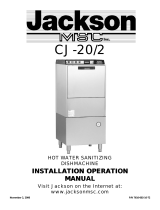
JPX-300H/HC DIMENSIONS
4
DIMENSIONS
Height (minimum): 33 1/4” (84.5 cm) Inside Clearance Height: 14 1/2” (36.8 cm)
Height (maximum): 34 1/4” (87 cm) Inside Clearance Width: 20 1/4” (51.4 cm)
Width: 24” (60.9 cm) Inside Clearance Depth: 21 1/4” (54 cm)
Depth: 22 5/8” (57.5 cm) Door Open Depth: 39 1/2” (100.3 cm)
Wall Clearance (minimum): 2 1/2” (6.4 cm)
*All dimensions are for reference only and are subject to change without notice.
LEGEND
A - Water Inlet 1/2” Female Pipe Thread, 2 1/2” AFF
B - Chemical Feeder Connection
C - Electrical Connection
D - Rinse Additive Connection
E - Drain Connection Flexible Hose 6’ Free Length,
1” ID x 1 3/8” OD
12”
(30.5 cm)
19”
(48.3 cm)
24”
(60.9 cm)
33 1/4”
(84.5 cm)
6 1/2”
(16.5 cm)
8 1/2”
(21.6 cm)
13 1/4”
(33.7 cm)
4 5/8” (11.7 cm)
4 1/4”
(10.8 cm)
2 1/4”
(5.7 cm)
22 5/8”
(57.5 cm)
16 3/4”
(42.5 cm)
4 1/2”
(11.4 cm)
C

JPX-300 Installation/Operation Manual 7610-002-71-26 Rev. J
Issued: 03-09-2006 Revised: N/A
SECTION 1: SPECIFICATION INFORMATION
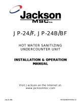
JPX-300HN DIMENSIONS
5
LEGEND
A - Water Inlet 1/2” ID Female Pipe Thread, 2 1/2” AFF
B - Detergent Feeder Connection
C - Electrical Connection
D - Drain Connection Flexible Hose 6’ Free Length,
1” ID x 1 3/8” OD
E - Rinse Additive Connection
DIMENSIONS
Height (minimum): 33 1/4” (84.5 cm) Inside Clearance Height: 14 1/2” (36.8 cm)
Height (maximum): 34 1/4” (87 cm) Inside Clearance Width: 20 1/4” (51.4 cm)
Width: 24” (60.9 cm) Inside Clearance Depth: 21 1/4” (54 cm)
Depth: 22 5/8” (57.5 cm) Door Open Depth: 39 1/2” (100.3 cm)
Wall Clearance (minimum): 2 1/2” (6.4 cm)
*All dimensions are for reference only and are subject to change without notice.
A
A
C
E
C
D
E
B
24”
(60.9 cm)
22 5/8”
(57.5 cm)
16 3/4”
(42.5 cm)
DOOR OPEN
19”
(48.3 cm)
4 1/4”
(10.8 cm)
33 1/4”
(84.5 cm)
6 1/2”
(16.5 cm)
4 1/2”
(11.4 cm)
8 1/2”
(21.6 cm)
4 5/8” (11.7 cm)
2 1/4” (5.7 cm)
2 1/4”
(5.7 cm)
12”
(30.5 cm)
2 1/2” (6.4 cm) Min. Wall Clearance
13 1/4”
(33.7 cm)

JPX-300 Installation/Operation Manual 7610-002-71-26 Rev. J
Issued: 03-09-2006 Revised: N/A
SECTION 1: SPECIFICATION INFORMATION
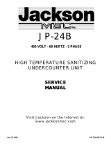
JPX-300L DIMENSIONS
6
2-
1
2
"
Minimum
Wall
Clearance
22-5/8"
33-1/4"
24"
C
B
12"
D
C
19"
D
B
A
E
3-3/4"
8-1/2"
6-3/8" 3-7/8"
12-13/16"
12 13/16”
(84.5 cm)
LEGEND
A - Detergent Feeder Connection
B - Electrical Connection
C - Water Inlet 1/2” Female Pipe Thread, 2 1/2”
AFF
D - Rinse Additive Connection
E - Drain Connection Flexible Hose 6’ Free
Length, 1” ID x 1 3/8” OD
DIMENSIONS
Height (minimum): 33 1/4” (84.5 cm) Inside Clearance Height: 14 1/2” (36.8 cm)
Height (maximum): 34 1/4” (87 cm) Inside Clearance Width: 20 1/4” (51.4 cm)
Width: 24” (60.9 cm) Inside Clearance Depth: 21 1/4” (54 cm)
Depth: 22 5/8” (57.5 cm) Door Open Depth: 39 1/2” (100.3 cm)
Wall Clearance (minimum): 2 1/2” (6.4 cm)
*All dimensions are for reference only and are subject to change without notice.
24”
(60.9 cm)
22 5/8”
(57.5 cm)
19”
(48.3 cm)
3 3/4” (9.5 cm)
3 7/8”
(9.8 cm)
33 1/4”
(84.5 cm)
24”
(61 cm)
8 1/2”
(21.6 cm)
3 3/4”
(9.5 cm)
3 7/8”
(9.8 cm)

7
SECTION 2:
INSTALLATION/OPERATION
INSTRUCTIONS

JPX-300 Installation/Operation Manual 7610-002-71-26 Rev. J
Issued: 03-09-2006 Revised: 09-14-2006
SECTION 2: INSTALLATION/OPERATION INSTRUCTIONS
8
INSTALLATION INSTRUCTIONS
VISUAL INSPECTION: Before installing the unit, check the container and machine for damage. Adamaged container is an indi-
cator that there may be some damage to the machine. If there is damage to both the container and machine, do not throw away
the container. The dishmachine has been inspected and packed at the factory and is expected to arrive to you in new, undam-
aged condition. However, rough handling by carriers or others may result in there being damage to the unit while in transit. If
such a situation occurs, do not return the unit to Jackson; instead, contact the carrier and ask them to send a representative to
the site to inspect the damage to the unit and to complete an inspection report. You must contact the carrier within 48 hours of
receiving the machine. Also, contact the dealer through which you purchased the unit.
UNPACKING THE DISHMACHINE: Once the machine has been removed from the container, ensure that there are no miss-
ing parts from the machine. This may not be obvious at first. If it is discovered that an item is missing, contact Jackson imme-
diately to have the missing item shipped to you.
LEVEL THE DISHMACHINE: The dishmachine is designed to operate while being level.
This is important to prevent any damage to the machine during operation and to ensure the
best results when washing ware. The unit comes with adjustable bullet feet, which can be
turned using a pair of channel locks or by hand if the unit can be raised safely. Ensure that
the unit is level from side to side and from front to back before making any connections.
PLUMBING THE DISHMACHINE: All plumbing connections must comply with all applica-
ble local, state, and national plumbing codes. The plumber is responsible for ensuring that
the incoming water line is thoroughly flushed prior to connecting it to any component of the
dishmachine. It is necessary to remove all foreign debris from the water line that may poten-
tially get trapped in the valves or cause an obstruction. Any valves that are fouled as a result
of foreign matter left in the water line, and any expenses resulting from this fouling, are not
the responsibility of the manufacturer. A water hardness test must be performed to deter-
mine if the HTS-11 (scale prevention and corrosion control) need to be installed. A hardness
test kit is attached to the warning tag that is attached to the y-strainer toward the front of the
machine. If the hardness is higher than 5 GPG the HTS-11 will need to be installed, please
contact Jackson immediately to have this item shipped to you.
WATER SUPPLY CONNECTION FOR MACHINES WITH A WATER HARDNESS
GREATER THAN 5 GPG: Ensure that you have read the section entitled “PLUMBING THE
DISHMACHINE” above before proceeding. Install the HTS-11 into the water line (1/2” ID
pipe size minimum) before the dishmachine line y-strainer using copper pipe. The HTS-11
must be installed vertically. A mounting bracket is provided to facilitate the venture metering
head to the wall. Observe proper inlet/outlet water directions. Flow directions are molded
into the top of the head. It is recommended that a water shut-off valve be installed before
the HTS-1 to allow access for servicing. Plumb from the HTS-11 outlet to the y-strainer using
copper pipe (or order the 1/2” ID flexible hose kit offered by Jackson). The water supply line
is to be capable of 20±5 PSI “flow” pressure at the recommended temperature indicated on
the data plate. See “Pressure Regulator” and “Shock Absorber” sections.
WATER SUPPLY CONNECTION FOR MACHINES WITH A WATER HARDNESS OF 5
GPG OR LESS:Ensure that you have read the section entitled “PLUMBING THE DISHMA-
CHINE” above before proceeding. Install the water supply line (1/2” ID pipe size minimum)
to the dishmachine line y-strainer using copper pipe (or order the 1/2” ID flexible hose kit
offered by Jackson). It is recommended that a water shut-off valve be installed in the water
line between the main supply and the machine to allow access for service. The water sup-
ply line is to be capable of 20±5 PSI “flow” pressure at the recommended temperature indi-
cated on the data plate.
PRESSURE REGULATOR: Do to areas where the water pressure fluctuates or is greater
than the recommended pressure, it is recommended installing a water pressure regulator. Do not confuse static pressure with
flow pressure. Static pressure is the line pressure in a “no flow” condition (all valves and services are closed). Flow pressure
is the pressure in the fill line when the fill valve is opened during the cycle.
Adjustable Bullet Foot
Incoming Plumbing Y-Strainer
Back of Machine Showing Drain Hose
Drain Hose

SHOCK ABSORBER: It is also recommended that a shock absorber (not supplied with the JPX-300 series models) be installed
in the incoming water line. This prevents line hammer (hydraulic shock), induced by the solenoid valve as it operates, from
causing damage to the equipment.
CONNECTING THE DRAIN LINE: The JPX-300 series machines are a pumped (pressure) drain capable of pumping waste
water to a height of 24 inches from the floor to the kitchen’s drain system. The dishmachines are supplied with a 10 foot long
hose that extends from the rear side of the machine. There must also be an air gap between the machine drain line and the
floor sink or drain. If a grease trap is required by code, it should have a flow capacity of 12 gallons per minute.
PLUMBING CHECK: Slowly turn on the water supply to the machine after the incoming fill line and the drain line have been
installed. Check for any leaks and repair as required. All leaks must be repaired prior to placing the machine in operation.
ELECTRICAL POWER CONNECTION: Electrical and grounding connections
must comply with the applicable portions of the National Electrical Code
ANSI/NFPA 70 (latest edition) and/or other electrical codes.
Disconnect electrical power supply and place a tag at the disconnect switch to
indicate that you are working on the circuit.
The dishmachine data plate is located on the front of the machine. Refer to the
data plate for machine operating requirements, machine voltage, total amper-
age load and serial number.
To install the incoming power lines, remove the kick panel. This will require tak-
ing a phillips head screwdriver and removing the two screws at the bottom of
the kick panel; open the door slightly while carefully lifting the kick panel up
and out of the way. Install 3/4” conduit into the pre-punched holes in the back
of the control box. Route power wires and connect to power block and ground-
ing lug. Install the service wires (L1 and L2) to the appropriate terminals as
they are marked on the terminal block. Install the grounding wire into the lug
provided. It is recommended that “DE-OX” or another similar anti-oxidation
agent be used on all power connections.
VOLTAGE CHECK: Ensure that the power switch is in the
OFF position and apply power to the dishmachine. Check
the incoming power at the terminal block and ensure it cor-
responds to the voltage listed on the data plate. If not, con-
tact a qualified service agency to examine the problem. Do
not run the dishmachine if the voltage is too high or too
low. Shut off the service breaker and mark it as being for
the dishmachine. Advise all proper personnel of any prob-
lems and of the location of the service breaker. Replace
the control box cover and tighten down the screws.
CHEMICAL CONNECTIONS: All chemical hookup loca-
tions are located on the back of the dishmachine. Please
refer to the drawing at the right for the correct connection
point. The JPX-300H/HC/HN dishmachines are supplied
with integral detergent and rinse aid chemical feeder
pumps. The JPX-300L dishmachine is supplied with inte-
gral detergent, rinse additive and sanitizer chemical feed-
er pumps.
Please refer to page 11 for instructions on priming the chemical feeder pumps.
JPX-300 Installation/Operation Manual 7610-002-71-26 Rev. J
Issued: 03-09-2006 Revised: 9-14-2006
SECTION 2: INSTALLATION/OPERATION INSTRUCTIONS
9
ELECTRICAL INSTALLATION INSTRUCTIONS
Control Box Electrical Connection
Ground Lug
Terminal Block
Back of Unit Showing Chemical Connection Points
Rinse Aid Fitting
Brass Plug
Detergent Fitting

JPX-300 Installation/Operation Manual 7610-002-71-26 Rev. J
Issued: 03-09-2006 Revised: N/A
SECTION 2: INSTALLATION/OPERATION INSTRUCTIONS
10
WARNING: CHLORINE-BASED SANITIZERS CAN BE DETRIMENTAL TO YOUR MACHINE IF THE CHEMICAL
SOLUTION IS TOO STRONG. SEE YOUR CHEMICAL PROFESSIONAL TO ENSURE YOUR DISPENSER IS SET UP
CORRECTLY.
This equipment is not recommend for use with deionized water or other aggressive fluids. Use of deionized water or
other aggressive fluids will result in corrosion and failure of materials and components. Use of deionized water or
other aggressive fluids will void the manufacturer's warranty.
T
O PREPARE CHEMICAL
FEEDER PUMPS FOR OPERATION
The JPX-300H/HC/HN dishmachines are supplied with integral detergent and rinse aid chemical feeder pumps. The JPX-300L
dishmachine is supplied with integral detergent, rinse additive and sanitizer chemical feeder pumps. Locate the open ends of
the chemical tubes with the tube stiffeners and place each one in the appropriate container.
A. Red Tubing = Detergent
B. Blue Tubing = Rinse Aid
C. White Tubing = Sanitizer
PRIMING CHEMICAL
FEEDER PUMPS
Chemical feeder pumps need priming when the machine is first installed or if for some reason the chemical lines have been
removed and air is allowed to enter.
CAUTION: Water must be in the sump and wash tank prior to the dispensing of chemicals. Sanitizer in concentration is
caustic and may cause damage without dilution.
1. Verify that the proper chemical tube stiffener inlet is in the proper container.
2. Use the prime switches located at the top of the unit to prime each pump. The switches are clearly marked (“D”, “R”, and
“S”) as to what chemical feeder pump they are assigned to.
3. To prime the pumps, hold the switch in the momentary position until chemical can be observed entering the sump.
4. Detergent is dispensed as required during the wash cycle by the cam timer. The amount of detergent may need to be
increased or decreased depending on water quality and type of detergent. It is adjusted by changing the detergent cam on the
cam timer.
5. Rinse additive is dispensed as required into the final rinse. The amount of rinse aid may need to be adjusted depending on
water hardness and results. It can be changed by changing the rinse cam on the cam timer.
6. Sanitizer (either chlorine or iodine) is dispensed into the final rinse. The amount of sanitizer may need to be adjusted
depending on the concentration and type of sanitizer used. It is adjusted by changing sanitizer cam on the cam timer.
WARNING: Some of the chemicals used in dishwashing may cause chemical burns if they come in contact with
your skin. Wear protective gear when handling these chemicals. If you do come in contact with these chemi-
cals, immediately flush the affected area with fresh water.
CHEMICAL DISPENSING EQUIPMENT

JPX-300 Installation/Operation Manual 7610-002-71-26 Rev. J
Issued: 03-09-2006 Revised: 03-06-2007
SECTION 2: INSTALLATION/OPERATION INSTRUCTIONS
11
To access the programming mode, the machine must be ON, and idle (between cycles).
On the timer board, press and hold both the MOVE and ENTER buttons on the timer board simultaneously for two seconds.
The PROGRAM (PGM) light and light A will illumniate.
Note: Once in the programming mode, the MOVE button is used to scroll between the programming categories and the ENTER
button is used to select the category.
Press the MOVE button to move the solid light to the desired location of FILL, RINSE AID, DETERGENT or SANITIZER. Please
note that options A, B, C, and D are not adjustable outputs.
Press the ENTER button for the chosen category. Now, the (PGM) light will illuminate along with lights corresponding to the
time values forthe chosen category. The ACCEPT light will blink.
The PROGRAM light will illuminate.
To change the value of a parameter, use the MOVE button to illuminate the light next to the time option (time is in seconds). In
the time categories, each second in use will light up. To deselect the option, press ENTER and the light will go off, press ENTER
again and it will illuminate. Once you have set your time category, press the MOVE button until the ACCEPT light illuminates
and press ENTER. This will save the changed parameters.
Once you press the ENTER button when the ACCEPT light is blinking you will exit the programming mode. To change any other
values, you will have to return to the programming mode. To revert back to a previous setting, you must return to that option
and change the parameter back to the previous setting.
Once in the programming mode, if there have been no keypad inputs for approximately 2 minutes, the system will automati-
cally exit out of the programming mode. Any changes to parameters will be saved when the programming mode is automati-
cally exited.
The wash and drain settings are not adjustable.
All time adjustments are in seconds. Refer to the chart below for the adjustable outputs.
PROGRAMMING INSTRUCTIONS FOR CHEMICAL FEEDER PUMPS (FOR INSTALLATION TECHNICIAN ONLY)
Time in seconds.
Timer Programming Board
JPX-300H JPX-300L
Not adjustable Rinse Aid
Rinse Fill
Detergent Sanitizer
Rinse Aid Detergent

JPX-300 Installation/Operation Manual 7610-002-71-26 Rev. J
Issued: 03-09-2006 Revised: N/A
SECTION 2: INSTALLATION/OPERATION INSTRUCTIONS
12
Detergent usage and water hardness are two factors that contribute greatly to how efficiently your dishmachine will operate.
Using detergent in the proper amount can become, in time, a source of substantial savings. A qualified water treatment spe-
cialist can tell you what is needed for maximum efficiency from your detergent, but you should still know some basics so you’ll
understand what they are talking about.
First, you must understand that hard water greatly effects the performance of the dishmachine. Water hardness is the amount
of dissolved calcium and magnesium in the water supply. The more dissolved solids in the water, the greater the water hard-
ness. Hard water works against detergent, thereby causing the amount of detergent required for washing to increase. As you
use more detergent, your costs for operating the dishmachine will increase and the results will decrease. The solids in hard
water also may build-up as a scale on wash and rinse heaters, decreasing their ability to heat water. Water temperature is
important in removing soil and sanitizing dishes. If the water cannot get hot enough, your results may not be satisfactory. This
is why Jackson recommends that if you have installed the machine in an area with hard water, that you also install some type
of water treatment equipment to help remove the dissolved solids from the water before it gets to the dishmachine.
Second, hard water may have you adding drying agents to your operating cycle to prevent spotting, when the real problem is
deposited solids on your ware. As the water evaporates off of the ware, the solids will be left behind to form the spotting and
no amount of drying agent will prevent this. Again, using treated water will undoubtedly reduce the occurrences of this prob-
lem.
Third, treated water may not be suitable for use in other areas of your operation. For instance, coffee made with soft water may
have an acid or bitter flavor. It may only be feasible to install a small treatment unit for the water going into the dishmachine
itself. Discuss this option with your qualified water treatment specialist.
Even after the water hardness problems have been solved, there still must be proper training of dishmachine operators in how
much detergent is to be used per cycle. Talk with your water treatment specialist and detergent vendor and come up with a
complete training program for operators. Using too much detergent has as detrimental effects as using too little. The proper
amount of detergent must be used for job. It is important to remember that certain menu items may require extra detergent by
their nature and personnel need to be made aware of this. Experience in using the dishmachine under a variety of conditions,
along with good training in the operation of the machine, can go a long way in ensuring your dishmachine operates as effi-
ciently as possible.
Certain dishmachine models require that chemicals be provided for proper operation and sanitization. Some models even
require the installation of third-party chemical feeders to introduce those chemicals to the machine. Jackson does not recom-
mend or endorse any brand name of chemicals or chemical dispensing equipment. Contact your local chemical distributor for
questions concerning these subjects.
Some dishmachines come equipped with integral solid detergent dispensers. These dispensers are designed to accommodate
detergents in a certain sized container. If you have such a unit, remember to explain this to your chemical distributor upon first
contacting them.
As explained before, water temperature is an important factor in ensuring that your dishmachine functions properly. The data
plate located on each unit details what the minimum temperatures must be for either the incoming water supply, the wash tank
and the rinse tank, depending on what model of dishmachine you have installed. These temperatures may also be followed by
temperatures that Jackson recommends to ensure the highest performance from you dishmachine. However, if the minimum
requirements are not met, the chances are your dishes will not be clean or sanitized. Remember, a dish can look clean, but it
may not be sanitized. Instruct your dishmachine operators to observe the required temperatures and to report when they fall
below the minimum allowed. A loss of temperature can indicate a much larger problem such as a failed heater or it could also
indicate that the hot water heater for your operation is not up to capacity and a larger one may need to be installed.
There are several factors to consider when installing your dishmachine to ensure that you get the best possible results from it
and that it operates at peak efficiency for many years. Discuss your concerns with your local chemical distributor and water
treatment specialist before there is a problem.
DETERGENT CONTROL

JPX-300 Installation/Operation Manual 7610-002-71-26 Rev. J
Issued: 03-09-2006 Revised: N/A
SECTION 2: INSTALLATION/OPERATION INSTRUCTIONS
PREPARATION: Before proceeding with the start-up of the unit, verify the following:
1. The strainer is in place and is clean.
2. That the wash and rinse arms are screwed securely into place and that their endcaps are tight. The wash and rinse arms
should rotate freely.
3. Verify all chemical levels for machine chemical feeder pumps are correct.
POWER UP: To energize the unit, turn on the power at the service breaker. The voltage should have been previously verified
as being correct. If not, the voltage will have to be verified.
FILLING THE WASH TUB: For the initial fill, close the door and ensure that the MANUAL switch light is not on. Depress and
hold the START CYCLE switch until the auto light comes on and releases. For the initial fill, run the machine through 3 cycles
to fill the tub sump. The machine will run a partial cycle and fill to the bottom of the pan strainer. Open the door and verify that
the water level is correct.
NOTE: For the JPX-300H/JPX-300HC: Ensure the orange/white wires at the heater contactor are connected prop-
erly. They have been purposely disconnected at the factory to avoid damage to the heater element when there
is no water in the booster heater.
Hereafter, the water level is controlled by the timer that has been preset at the factory. Verify that there are no other leaks on
the unit before proceeding any further. The wash sump must be completely filled before operating the wash pump to prevent
damage to the component. Once the wash tub is filled, the unit is ready for operation.
The machine runs a complete cycle to drain and fill. If the machine is not allowed to drain, the water will build up inside the tub.
After the initial fill, the rinse water for the current cycle will become the wash water for the next cycle.
WARE PREPARATION: Proper preparation of ware will help ensure good results and less re-washes. If not done properly, ware
may not come out clean and the efficiency of the dishmachine will be reduced. It is important to remember that a dishmachine
is not a garbage disposal and that simply throwing unscraped dishes into the machine simply defeats the purpose altogether
of washing the ware. Scraps should be removed from ware prior to being loaded into a rack. Pre-rinsing and pre-soaking are
good ideas, especially for silverware and casserole dishes. Place cups and glasses upside down in racks so that they do not
hold water during the cycle. The dishmachine is meant not only to clean, but to sanitize as well, to destroy all of the bacteria
that could be harmful to human beings. In order to do this, ware must be properly prepared prior to being placed in the machine.
DAILY MACHINE PREPARATION: Refer to the section entitled “PREPARATION” at the top of this page and follow the instruc-
tions there. Afterwards, check that all of the chemical levels are correct and/or that there is plenty of detergent available for the
expected workload.
WARM-UP CYCLES: For a typical daily start-up, it is recommended to run the machine through 3 cycles to ensure that all of
the cold water is out of the system and to verify that the unit is operating correctly. To cycle the machine, ensure that the power
is on and that the tub has filled to the correct level.
Press the START CYCLE button and hold until the green auto light
is on and releases, the unit will start, run through the cycle,
and shut off automatically. Repeat this two more times. The unit should now be ready to proceed with the washing of ware.
WASHING A RACK OF WARE: To wash a rack, open the door completely and slide the rack into the unit. Close the door, press
the START CYCLE button and hold until the green auto light is on and releases, the unit will start. Once the cycle is complet-
ed, open the door and remove the rack of clean ware. Replace with a rack of soiled ware and close the door. The process will
then repeat itself.
OPERATIONAL INSPECTION: Based upon usage, the pan strainer may become clogged with soil and debris as the workday
progresses. Operators should regularly inspect the pan strainer to ensure it has not become clogged. If the strainer does, it will
reduce the washing capability of the machine. Instruct operators to clean out the pan strainer at regular intervals or as required
by work load.
OPERATION INSTRUCTIONS
13

JPX-300 Installation/Operation Manual 7610-002-71-26 Rev. J
Issued: 03-09-2006 Revised: 09-14-2006
SECTION 2: INSTALLATION/OPERATION INSTRUCTIONS
14
SHUTDOWN AND CLEANING: At the end of the workday, close the door. Start a cycle. Wait approximately five seconds after
the green auto light comes on and then push the POWER OFF switch. This will put the machine in shutdown mode which will
let the machine drain completely prior to shutting off. Once the wash tub is drained and power light is off, remove he pan strain-
er. Remove soil and debris from the strainer and set to the side. Unscrew the wash and rinse arms from their manifolds.
Remove the endcaps and flush the arms with water. Use a brush to clean out the inside of the arms. If the nozzles appear to
be clogged, use a toothpick to remove the obstruction. Wipe the inside of the unit out, removing all soil and scraps. Reassemble
the wash and rinse arms and replace them in the unit. The arms only need to be hand tight, do not use tools to tighten them
down. Reinstall the strainer and close the door.
DELIMING OPERATIONS: In order to maintain the dishmachine at its optimum performance level, it will be required to remove
lime and corrosion deposits on a frequent basis. Adeliming solution should be available from your detergent supplier. Read and
follow all instructions on the label of the deliming solution.
NOTE: If this machine is equipped with a HTS-11, scale prevention and corrosion control device, and lime is becoming a fre-
quent problem, the cartridge needs to be replaced. To order a replacement cartridge, call Jackson immediately to have one
shipped to you.
To proceed with the deliming operation, fill the dishmachine and add the correct amount of deliming solution as recommended
by the deliming solution manufacturer. The water capacity of the tank can be verified on the specification sheet(s) of this man-
ual.
Perform the following operations to delime the dishmachine:
1. Push Manual Switch on the front of the control panel.
2. Disconnect or turn off all chemical feeder pumps.
3. Close all doors (after adding the deliming solution).
4. Run the machine for the recommended period of time.
5. Press the Power Switch to turn the unit off and open the doors.
6. Wait five minutes, then inspect the inside of the machine. If the machine is not delimed, run another time cycle as per the
deliming solution’s instructions.
7. When clean, drain and re-fill the machine.
8. Run in MANUAL for 10 minutes to remove residual deliming solution.
9. Drain and re-fill the machine.
OPERATION INSTRUCTIONS (CONTINUED)/DELIMING INSTRUCTIONS
/