Page is loading ...

For more information, visit www.desatech.com
WARNING: If the information in this manual is not fol-
— WHAT TO DO IF YOU SMELL GAS
• Do not touch any electrical switch; do not use any
-
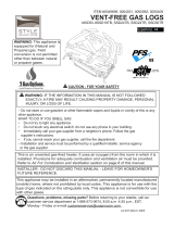
VF-30N-PJD, VF-30P-PJD
VF-24N-PJD, VF-24P-PJD
VF-18N-PJD, VF-18P-PJD
UNVENTED (VENT-FREE) GAS LOG HEATER
OWNER’S OPERATION AND INSTALLATION MANUAL

www.desatech.com
111826-04C2
SAFETy INFORMATION
TABLE OF CONTENTS
Safety Information ............................................... 2
Product Identication ........................................... 4
Local Codes......................................................... 5
Unpacking............................................................ 5
Product Features ................................................. 5
Air For Combustion and Ventilation ..................... 5
Installation ........................................................... 8
Operating Heater ............................................... 14
Inspecting Burners ............................................ 18
Cleaning and Maintenance ................................ 19
Troubleshooting ................................................. 20
Wiring Diagram .................................................. 23
Service Hints ..................................................... 24
Technical Service............................................... 24
Replacement Parts ............................................ 24
Specications .................................................... 25
Accessories ....................................................... 25
Illustrated Parts Breakdown and Parts List........ 26
Warranty Information ...........................Back Cover
-
-
teration, service or main-
to this manual for correct
-
-
tance or additional infor-
is for installation only in a
-
-
installations in accor-
-
includes instructions stat-
WARNING: This is an
-
from the room in which
and ventilation air must
Air
for Combustion and Ven-
tilation
-
stalled in an aftermarket,*
-

www.desatech.com
111826-04C 3
-
known to the State of California
Early signs of carbon
monoxide poisoning resemble the u, with head-
aches, dizziness or nausea. If you have these signs,
the heater may not be working properly. Get fresh
air at once! Have heater serviced. Some people
are more affected by carbon monoxide than others.
These include pregnant women, people with heart
or lung disease or anemia, those under the inuence
of alcohol and those at high altitudes.
Natural and pro-
pane/LP gases are odorless. An odor-making
agent is added to these gases. The odor helps you
detect a gas leak. However, the odor added to the
gas can fade. Gas may be present even though no
odor exists.
Make certain you read and understand all warn-
ings. Keep this manual for reference. It is your
guide to safe and proper operation of this heater.
this heater or its controls can
WARNING: Do not use a
-
SAFETy INFORMATION
Continued
WARNING: Do not allow fans
will remain hot for a time after
-
dren when they are in the room
-
-

www.desatech.com
111826-04C4
1. This appliance is only for use with the type of
gas indicated on the rating plate. This appliance
is not convertible for use with other gases.
2. Do not place propane/LP supply tank(s) in-
side any structure. Locate propane/LP supply
tank(s) outdoors (propane/LP units only).
3. If you smell gas
• shut off gas supply
• do not try to light any appliance
• do not touch any electrical switch; do not
use any phone in your building
• immediately call your gas supplier from
a neighbor’s phone. Follow the gas
supplier’s instructions
• if you cannot reach your gas supplier, call
the re department
4. This heater shall not be installed in a bedroom
or bathroom.
5. Before installing in a solid fuel burning re-
place, the chimney ue and rebox must be
cleaned of soot, creosote, ashes and loose paint
by a qualied chimney cleaner. Creosote will
ignite if highly heated. Inspect chimney ue
for damage. If damaged, repair ue before
operating heater.
6. Do not burn solid-fuel in a masonry or UL127
factory-built replace in which a vent-free
room heater is installed.
7. If replace has glass doors, never operate this
heater with glass doors closed. If you operate
heater with doors closed, heat buildup inside
replace will cause glass to burst. Make sure
there are no obstructions across openings of
replace.
8. To prevent the creation of soot, follow the
instructions in Cleaning and Maintenance,
page 19.
9. Before using furniture polish, wax, carpet
cleaner or similar products, turn heater off. If
heated, the vapors from these products may
create a white powder residue within burner
box or on adjacent walls or furniture.
10. This heater needs fresh, outside air ventilation to
run properly. This heater has an oxygen depletion
sensing (ODS) pilot light safety system. The
ODS shuts down the heater if not enough fresh
air is available. See Air for Combustion and
Ventilation, page 5. If heater keeps shutting off,
see Troubleshooting, page 20.
11. Do not run heater
• where ammable liquids or vapors are used
or stored
• under dusty conditions
SAFETy INFORMATION
Continued
12. Do not use this heater to cook food or burn
paper or other objects.
13. Do not use heater if any part has been exposed
to or under water. Immediately call a qualied
service technician to inspect the room heater
and to replace any part of the control system and
any gas control which has been under water.
14. Do not operate heater if any log is broken. Do
not operate heater if a log is chipped (dime-
sized or larger).
15. Turn heater off and let cool before servicing
or repairing. Only a qualied service person
should install, service or repair heater.
16. This heater does not need to be connected to
any external electrical source.
17. To prevent performance problems, do not
use propane/LP fuel tank of less than 100 lb.
capacity (propane/LP units only).
18. Operating heater above elevations of 4,500
feet could cause pilot outage.
19. Provide adequate clearances around air
openings.
State of Massachusetts: The installa-
tion must be made by a licensed plumber
or gas fitter in the Commonwealth of
Massachusetts.
Sellers of unvented propane or natural
gas-red supplemental room heaters shall
provide to each purchaser a copy of 527
CMR 30 upon sale of the unit.
Vent-free gas products are prohibited for
bedroom and bathroom installation in the
Commonwealth of Massachusetts.
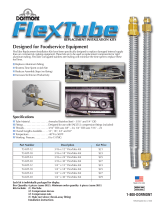
PRODUCT
IDENTIFICATION
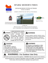
Figure 1 - Product Identication
Hand-Held
Remote Control
Chassis
Assembly
Control
Valve
Log Set
Assembly

www.desatech.com
111826-04C 5
LOCAL CODES
Install and use heater with care. Follow all local
codes. In the absence of local codes, use the lat-
est edition of The National Fuel Gas Code ANSI
Z223.1/NFPA 54*.
*Available from:
American National Standards Institute, Inc.
1430 Broadway
New York, NY 10018
National Fire Protection Association, Inc.
Batterymarch Park
Quincy, MA 02269
UNPACkING
CAUTION: Do not remove the
-
1. Remove log set assembly from carton.
Note: Do not pick up assembly by logs. This
could damage heater. Always handle assembly
by grate.
2. Remove control cover oor media components.
3. Remove all protective packaging applied to
log set for shipment.
3. Check all items for any shipping damage. If
damaged, promptly inform dealer where you
bought heater.
PRODUCT FEATURES
This heater is clean burning. It requires no outside
venting. There is no heat loss out a vent or up a
chimney. Heat is generated by realistic ames and
glowing ceramic logs/coals. This heater is designed
for vent-free operation with ue damper closed. It has
been tested and approved to ANSI Z21.11.2 standard
for unvented heaters. State and local codes in some
areas prohibit the use of vent-free heaters.
This heater has a pilot with an Oxygen Deple-
tion Sensing (ODS) safety shutoff system. The
ODS/pilot is a required feature for vent-free room
heaters. The ODS/pilot shuts off the heater if there
is not enough fresh air.
REMOTE IGNITION AND CONTROL
This gas log set has a battery powered electronic
remote ignition and control. This system requires
no matches or other source to light log set.
AIR FOR COMBUSTION
AND VENTILATION
WARNING: This heater shall
-
-
Today’s homes are built more energy efcient
than ever. New materials, increased insulation and
new construction methods help reduce heat loss
in homes. Home owners weather strip and caulk
around windows and doors to keep the cold air out
and the warm air in. During heating months, home
owners want their homes as airtight as possible.
While it is good to make your home energy efcient,
your home needs to breathe. Fresh air must enter
your home. All fuel-burning appliances need fresh
air for proper combustion and ventilation.
Exhaust fans, replaces, clothes dryers and fuel
burning appliances draw air from the house to
operate. You must provide adequate fresh air for
these appliances. This will insure proper venting
of vented fuel-burning appliances.
The following are excerpts from National Fuel
Gas Code, ANSI Z223.1/NFPA 54, Section 5.3,
Air for Combustion and Ventilation.
All spaces in homes fall into one of the three fol-
lowing ventilation classications:
1. Unusually Tight Construction
2. Unconned Space
3. Conned Space
The information on pages 5 through 7 will help you
classify your space and provide adequate ventilation.
The air that leaks around doors and windows may
provide enough fresh air for combustion and ven-
tilation. However, in buildings of unusually tight
construction, you must provide additional fresh air.

www.desatech.com
111826-04C6
construction where:
-
-11
2
and
and
If your home meets all of the three criteria
See Ventilation Air From Outdoors
If your home does not meet all of the three
Determining
Fresh-Air Flow For Heater Location
The National Fuel Gas Code, ANSI Z223.1/NFPA
54 denes a conned space as a space whose
volume is less than 50 cubic feet per 1,000 Btu
per hour (4.8 m
3
per kw) of the aggregate input
rating of all appliances installed in that space and
an unconned space as a space whose volume is
not less than 50 cubic feet per 1,000 Btu per hour
(4.8 m
3
per kw) of the aggregate input rating of
all appliances installed in that space. Rooms com-
municating directly with the space in which the
appliances are installed*, through openings not
furnished with doors, are considered a part of the
unconned space.
* Adjoining rooms are communicating only if
there are doorless passageways or ventilation grills
between them.
DETERMINING FRESH-AIR FLOW
FOR HEATER LOCATION
Use this work sheet to determine if you have a
conned or unconned space.
Includes the room in which you will install
heater plus any adjoining rooms with doorless pas-
sageways or ventilation grills between the rooms.
1. Determine the volume of the space (length x
width x height).
Length x Width x Height =__________cu. ft.
(volume of space)
Example: Space size 20 ft. (length) x 16 ft.
(width) x 8 ft. (ceiling height) = 2,560 cu. ft.
(volume of space)
If additional ventilation to adjoining room is
supplied with grills or openings, add the volume
of these rooms to the total volume of the space.
2. Multiply the space volume by 20 to determine
the maximum Btu/Hr the space can support.
__________ (volume of space) x 20 = (Maxi-
mum Btu/Hr the space can support)
Example: 2,560 cu. ft. (volume of space) x 20 =
51,200 (maximum Btu/Hr the space can support)
3. Add the Btu/Hr of all fuel burning appliances in
the space.
Vent-free replace __________ Btu/Hr
Gas water heater* __________ Btu/Hr
Gas furnace __________ Btu/Hr
Vented gas heater __________ Btu/Hr
Gas replace logs __________ Btu/Hr
Other gas appliances* + __________ Btu/Hr
Total = __________ Btu/Hr
* Do not include direct-vent gas appliances. Di-
rect-vent draws combustion air from the outdoors
and vents to the outdoors.
Example:
Gas water heater __________ Btu/Hr
Vent-free replace + __________ Btu/Hr
Total = __________ Btu/Hr
4. Compare the maximum Btu/Hr the space can
support with the actual amount of Btu/Hr used.
_________
Btu/Hr (maximum the space can support)
_________
Btu/Hr (actual amount of Btu/Hr used)
Example: 51,200 Btu/Hr (maximum the space
can support)
73,000 Btu/Hr (actual amount of
Btu/Hr used)
The space in the example is a conned space because
the actual Btu/Hr used is more than the maximum
Btu/Hr the space can support. You must provide ad-
ditional fresh air. Your options are as follows:
A. Rework worksheet, adding the space of an adjoin-
ing room. If the extra space provides an unconned
space, remove door to adjoining room or add
ventilation grills between rooms. See Ventilation
Air From Inside Building, page 7.
B. Vent room directly to the outdoors. See Ventila-
tion Air From Outdoors, page 7.
C. Install a lower Btu/Hr replace, if lower Btu/Hr
size makes room unconned.
AIR FOR COMBUSTION
AND VENTILATION
Continued
40,000
33,000
73,000

www.desatech.com
111826-04C 7
AIR FOR COMBUSTION
AND VENTILATION
Continued
If the actual Btu/Hr used is less than the maximum
Btu/Hr the space can support, the space is an uncon-
ned space. You will need no additional fresh air
ventilation.
WARNING: If the area in
-
in the National Fuel Gas Code,
ANSI Z223.1/NFPA 54 Section 5.3
This fresh air would come from an adjoining un-
conned space. When ventilating to an adjoining
unconned space, you must provide two permanent
openings: one within 12" of the ceiling and one
within 12" of the oor on the wall connecting the
two spaces (see options 1 and 2, Figure 2). You
can also remove door into adjoining room (see
option 3, Figure 2). Follow the National Fuel Gas
Code, ANSI Z223.1/NFPA 54, Section 5.3, Air for
Combustion and Ventilation for required size of
ventilation grills or ducts.
Figure 2 - Ventilation Air from Inside
Building
Or
Remove
Door into
Adjoining
Room,
Option
3
Ventilation Grills
Into Adjoining Room,
Option 2
Ventilation
Grills
Into Adjoining
Room,
Option 1
12"
12"
Provide extra fresh air by using ventilation grills or
ducts. You must provide two permanent openings:
one within 12" of the ceiling and one within 12"
of the oor. Connect these items directly to the
outdoors or spaces open to the outdoors. These
spaces include attics and crawl spaces. Follow the
National Fuel Gas Code, ANSI Z223.1/NFPA 54,
Section 5.3, Air for Combustion and Ventilation for
required size of ventilation grills or ducts.
IMPORTANT: Do not provide openings for inlet
or outlet air into attic if attic has a thermostat-
controlled power vent. Heated air entering the attic
will activate the power vent.
Figure 3 - Ventilation Air from Outdoors
Outlet
Air
Ventilated
Attic
Outlet
A
ir
Inlet
Air
Inlet Air
Ventilated
Crawl Space
To
Crawl
Space
To Attic

www.desatech.com
111826-04C8
INSTALLATION
NOTICE: This heater is intended
-
-
cleaned of soot, creosote, ashes
-
WARNING: Seal any fresh
air vents or ash clean-out doors
-
WARNING: Never install the
heater
• in a recreational vehicle
• where curtains, furniture, cloth-
are less than 42 inches from the
• in windy or drafty areas
CAUTION: This heater cre-
currents move heat to wall sur-
heater next to vinyl or cloth wall
-
the air exist, may discolor walls
IMPORTANT: Vent-free heaters add moisture to
the air. Although this is benecial, installing heater
in rooms without enough ventilation air may cause
mildew to form from too much moisture. See Air
for Combustion and Ventilation, page 5.
Use the correct gas type (natural or propane/LP)
for your unit. If your gas supply is not correct, do
not install heater. Call dealer where you bought
heater for proper type heater.
-

www.desatech.com
111826-04C 9
INSTALLATION AND CLEARANCES
WARNING: Maintain the
INSTALLATION
Continued
Carefully follow the instructions below. This will
ensure safe installation into a masonry, UL127-
listed manufactured replace or listed vent-free
rebox enclosure.
Minimum Clearances For Side
A. Clearances from the side of the fireplace
cabinet to any combustible material and wall
should follow diagram in Figure 4.
Example: The face of a mantel, bookshelf,
etc. is made of combustible material and
protrudes 3
1
/
2
" from the wall. This combus-
tible material must be 4" from the side of the
replace cabinet (see Figure 4).
Note: When installing your gas logs into
a manufactured firebox, follow firebox
manufacturer’s instructions for minimum
clearances to combustible materials.
B.
Clearances from the top of the replace opening
to the ceiling should not be less than 42 inches.
Figure 4 - Minimum Clearance for
Combustible to Wall
*Minimum 16 inches from Side Wall
*
Example
18" 17" 14" 24" 20"
24" 17" 14" 28" 22"
30" 24" 17
1
/
2
" 42" 28
3
/
4
"
CLEARANCE TO
18", 24", 30"
Side Wall 16"
42"
Floor 5"
*Measured at 14" depth
Clearances
Note: If using a mantel, proceed to If Using
Mantel. If not using a mantel, follow the informa-
tion below.
You must have noncombustible material(s) above
fireplace opening. Noncombustible materials
(such as slate, marble, tile, etc.) must be at least
1/2 inch thick. With sheet metal, you must have
noncombustible material behind it. Noncombus-
tible material must extend at least 8" up (for all
models). If noncombustible material is less than
12", you must install the replace hood accessory
24" and 30" models only). See Figure 5, page 10,
for minimum clearances.
You must have noncombustible material(s) above
the replace opening. Noncombustible materials
(such as slate, marble, tile, etc.) must be at least
1/2 inch thick. With sheet metal, you must have
noncombustible material behind it. Noncombus-
tible material must extend at least 8 inches up (for
all models). If noncombustible material is less than
12", you must install the replace hood accessory.
Even if noncombustible material is more than 12",
you may need the hood accessory to deect heat
away from your mantel shelf. See Figures 5, 6 and
7, page 10, for minimum clearances.

www.desatech.com
111826-04C10
Figure 6 - Minimum Mantel Clearances Without Using Hood
Minimum
Noncombustible
Material
Minimum
Noncombustible
Material Height
Distances to
Underside of
Mantel
Top of
Fireplace
Opening
Underside of
Mantel Shelf
Mantel Shelf
12"
(A)
18" 20" 22" 24"
All minimum
distances are
in inches
2
1
/2
"
6"
8"
10"
INSTALLATION
Continued
Figure 5 - Heat Resistant Material (Slate, Marble, Tile, etc.) Above Fireplace
12" or more Noncombustible material OK.
Between 8" 24" Model:Install re place hood accessory
and 12" (GA6060, see Accessories, page 25).
18" Model: Noncombustible material OK
Less than 8" Noncombustible material must be
extended to at least 8".
See Between 8"
and 12",
above. If you cannot
extend material,
you must
operate heater with ue damper
open.
Figure 7 - Minimum Mantel Clearances When Using Hood
Minimum
Noncombustible
Material
8"
Min.
12" 15" 18" 20"
2½"
6"
8"
10"
12"
Distances to
Underside of
Mantel
Hood
(GA6050,
GA6052 or
GA6053)
Top of
Fireplace
Opening
Underside
of Mantel
Shelf
Mantel Shelf

www.desatech.com
111826-04C 11
MANTEL CLEARANCES
In addition to meeting noncombustible material
clearances, you must also meet required clearances
between replace openings and mantel shelf on
each side of the replace. If you do not meet the
clearances listed below, you will need a hood.
If you meet minimum clearance between mantel
shelf and top of replace opening, a hood is not
required (see Figure 6, page 10).
If minimum clearances in Figure 6, page 11 are not
met, you must have a hood. When using a hood
there are still certain minimum mantel clearances
required. Follow minimum clearances shown in
Figure 7, page 10 when using hood.
-
-
Follow all minimum clearances
NOTICE: If your installation does
not meet the minimum clear-
ances shown, you must do one
-
• remove the mantel
FLOOR CLEARANCES
A. If installing appliance on the oor level, you
must maintain the minimum distance of 14"
to combustibles (see Figure 8).
B. If combustible materials are less than 14" to
the replace, you must install appliance at
least 5" above the combustible ooring (see
Figure 9).
INSTALLATION
Continued
Figure 8 - Minimum Fireplace Clearances
If Installed at Floor Level
Figure 9 - Minimum Fireplace Clearances
Above Combustible Flooring
14"
Min.
Combustible
Material
Noncombustible Material
Hearth
5"
Min.
Combustible
Material
CAUTION: Do not remove the
-
-
-
IMPORTANT: Make sure the heater burner is level.
If heater is not level, heater will not work properly.

www.desatech.com
111826-04C12
CAUTION: Never connect
-
WARNING: Never connect
is commonly known as wellhead
INSTALLATION
Continued
Fitting
Flexible Gas Hose
(if allowed by local codes)
Figure 10 - Attaching Flexible Gas Hose
to Regulator
Installation Items Needed
Before installing heater, make sure you have the
items listed below.
• external regulator (for propane/LP units only,
supplied by installer)
• piping (check local codes)
• sealant (resistant to propane/LP gas)
• equipment shutoff valve *
• test gauge connection *
• sediment trap
• tee joint
• pipe wrench
• approved exible gas line with gas connector
(if allowed by local codes) (not provided)
* A CSA design-certied equipment shutoff valve
with 1/8" NPT tap is an acceptable alternative to
test gauge connection. Purchase the optional CSA
design-certied equipment shutoff valve from your
dealer. See Accessories, page 25.
For propane/LP units, the installer must supply
an external regulator. The external regulator will
reduce incoming gas pressure. You must reduce
incoming gas pressure to between 11 and 14 inches
of water. If you do not reduce incoming gas pres-
sure, heater regulator damage could occur. Install
external regulator with the vent pointing down
as shown in Figure 11. Pointing the vent down
protects it from freezing rain or sleet.
Figure 11 - External Regulator With Vent
Pointing Down
Propane/LP
Supply Tank
External
Regulator
Vent
Pointing
Down
Installation Items Needed
• control cover kit (provided with heater)
• approved exible gas hose (not provided) (if
allowed by local codes)
• sealant (resistant to propane/LP gas, not
provided)
1. Apply pipe joint sealant lightly to male threads
of gas tting (not provided). Connect approved
exible gas hose to inlet side of gas control (see
Figure 10). IMPORTANT: Hold gas tting with
wrench when connecting exible gas hose.
2.
Position heater assembly in replace.
3. Connect to gas supply. See Connecting to
Gas Supply.

www.desatech.com
111826-04C 13
We recommend that you install a sediment trap in
supply line as shown in Figure 12. Locate sediment
trap where it is within reach for cleaning. Install
in piping system between fuel supply and heater.
Locate sediment trap where trapped matter is not
likely to freeze. A sediment trap traps moisture and
contaminants. This keeps them from going into
heater controls. If sediment trap is not installed or
is installed wrong, heater may not run properly.
INSTALLATION
Continued
Installation must include an equipment shutoff
valve, union and plugged 1/8" NPT tap. Locate NPT
tap within reach for test gauge hook up. NPT tap
must be upstream from heater (see Figure 12).
IMPORTANT: Install equipment shutoff valve
in an accessible location. The equipment shutoff
valve is for turning on or shutting off the gas to
the appliance.
Check your building codes for any special re-
quirements for locating equipment shutoff valve
to replaces.
Apply pipe joint sealant lightly to male NPT
threads. This will prevent excess sealant from
going into pipe. Excess sealant in pipe could result
in clogged heater valves.
* Purchase the optional CSA design-certified
equipment shutoff valve from your dealer. See
Accessories, page 25.
** Minimum inlet pressure for purpose of input
adjustment.
Figure 12 - Gas Connection
3" Minimum
CSA Design-Certied
Equipment Shutoff Valve
With 1/8" NPT Tap*
Approved
Flexible Gas
Hose (if allowed
by local codes)
Cap Pipe Tee
Nipple Joint
Sediment Trap
Natural Gas
From Gas Meter
(5" W.C.** to 10.5"
W.C. Pressure)
From External
Regulator
(11" W.C.** to
14" W.C.
Pressure)
CHECKING GAS CONNECTIONS
and connections, internal and
external to unit, for leaks after
WARNING: Never use an
-
CAUTION: Make sure exter-
-
der Connecting to Gas Supply,
1. Disconnect appliance with its appliance main
gas valve (control valve) and equipment
shutoff valve from gas supply piping system.
Pressures in excess of 1/2 psig will damage
heater regulator.
2. Cap off open end of gas pipe where equipment
shutoff valve was connected.
To Gas
Control

www.desatech.com
111826-04C14
INSTALLATION
Continued
CONNECTIONS
1. Open equipment shutoff valve (see Figure 13).
2. Open main gas valve located on or near gas
meter for natural gas or open propane/LP
supply tank valve.
3. Make sure control knob of heater is in the OFF
position.
4. Check all joints from equipment shutoff valve
to control valve (see Figure 14 or 15). Apply
noncorrosive leak detection uid to all joints.
Bubbles forming show a leak.
5. Correct all leaks at once.
6. Light heater (see Operating Heater). Check
all other internal joints for leaks.
7. Turn off heater (see To Turn Off Gas to Appli-
ance, page 17 or 18).
Figure 13 - Equipment Shutoff Valve
Open
Closed
Equipment
Shutoff Valve
Figure 15 - Checking Gas Joints for
Propane/LP Gas
Control Valve Location
Propane/LP
Supply Tank
Equipment Shutoff Valve
Figure 14 - Checking Gas Joints for
Natural Gas
Gas Meter
Equipment Shutoff Valve
Control Valve
Location
3. Pressurize supply piping system by either
opening propane/LP supply tank valve for
propane/LP gas or opening main gas valve
located on or near gas meter for natural gas
or using compressed air.
4. Check all joints of gas supply piping system.
Apply noncorrosive leak detection uid to all
joints. Bubbles forming show a leak.
5. Correct all leaks at once.
6. Reconnect heater and equipment shutoff
valve to gas supply. Check reconnected t-
tings for leaks.
1. Close equipment shutoff valve (see Figure 13).
2. Pressurize supply piping system by either
opening propane/LP supply tank valve for
propane/LP gas or opening main gas valve
located on or near gas meter for natural gas
or using compressed air.
3. Check all joints from gas meter to equipment
shutoff valve for natural gas or propane/LP sup-
ply to equipment shutoff valve for propane/LP
(see Figure 14 or 15). Apply noncorrosive leak
detection uid to all joints. Bubbles forming
show a leak.
4. Correct all leaks at once.
OPERATING HEATER
FOR YOUR SAFETY
WARNING: If you do not fol-
low these instructions exactly,
-
A. This appliance has a pilot which must be
lighted by hand. When lighting the pilot,
follow these instructions exactly.
B. BEFORE LIGHTING smell all around the
appliance area for gas. Be sure to smell next
to the oor because some gas is heavier than
air and will settle on the oor.

www.desatech.com
111826-04C 15
WHAT TO DO IF YOU SMELL GAS
• Do not try to light any appliance.
• Do not touch any electric switch; do not
use any phone in your building.
• Immediately call your gas supplier from
a neighbor’s phone. Follow the gas
supplier’s instructions.
• If you cannot reach your gas supplier,
call the re department.
C. Use only your hand to push in or turn the
gas control knob. Never use tools. If the
knob will not push in or turn by hand, don’t
try to repair it, call a qualied service tech-
nician or gas supplier. Force or attempted
repair may result in a re or explosion.
D. Do not use this appliance if any part has
been under water. Immediately call a
qualied service technician to inspect the
appliance and to replace any part of the
control system and any gas control which
has been under water.
REMOTE LIGHTING
INSTRUCTIONS
WARNING:
-
erate heater with doors closed,
-
OPERATING HEATER
Continued
Remain clear of the hearth area
1. STOP! Read the safety information begin-
ning on page 14.
2. Make sure equipment shutoff valve is fully
open.
3. Turn motor knob clockwise to the
OFF position.
4. Wait ve (5) minutes to clear out any gas.
Then smell for gas, including near the oor.
If you smell gas, STOP! Follow “B” in the
safety information, page 14. If you don’t
smell gas, go to the next step.
5. Make sure ON/OFF switch is in "–" (ON)
position.
on automatically within one min-
6. Press the buttons and at the same
time. A short acoustic signal conrms the
start sequence has begun.
Further short acoustic signals (0.2 sec., 1 Hz)
indicate the ignition process until it is com-
pleted and main gas ows. If pilot is already
lit, motor will turn on (max. ame height)
while buttons are pressed down. If pilot does
not light, see Troubleshooting, page 20.
7. Press to turn on main burner and in-
crease ame height. Press to decrease
ame height and shut off main burner.
8. Short tapping of either button allows incre-
mental change in ame height.
9. Press OFF button to switch off main gas
and pilot gas.
FUNCTIONS OF
REMOTE CONTROL
• After the charged battery has been correctly
installed, the remote hand set is ready for
operations.
• Remove the battery if the remote handset
will not be used more than one year.

www.desatech.com
111826-04C16
The control is radio frequency operated. A code
(chosen from among 4,000 available codes)
is preset for all valves, but can be changed
if required (15 additional codes available).
Change DIP switch position. (The DIP switch
is located inside the hand held control at the
top of the battery compartment.) Then press the
receiver's reset button until you hear a second
(longer) signal. When pressing the button
on the remote handset in the following 20 sec.,
the receiver learns the new code.
To save battery power; press to turn main
gas to pilot gas. Press OFF button to shut off
the device including pilot ame. The device can
be shut off with ON/OFF switch, thus disabling
the remote hand set.
Press and hold OFF and until display
changes from °F (and 12 hour clock) to °C (and
24 hour clock) or vice versa.
• After connecting the battery or by simulta-
neously pressing and the display will
start to ash. You are in the set mode.
• From SET mode press to set the hour and
to set the minute.
• Wait or press OFF to return to the manual
mode.
Remote handset battery needs to be changed
when LED is dim. Battery life expectancy is 2
to 3 years. Replacement is recommended at the
beginning of heating season. Battery needs to be
changed when acoustic error message appears
during ignition (see Identifying Error Signals
from Receiver on page 23).
• Press the SET button quickly to change the
mode of operation in the following order:
MAN, TEMP, TEMP, TIMER.
• Manual ame height adjustment (MAN ap-
pears on display): Press to turn on the re
(main burner) or to increase ame height.
Press to decrease ame or to go down
to pilot only. The receiver acknowledges the
transmission with an acoustic signal.
• The day time temperature mode ( TEMP ap-
pears on display): The sensor in the transmitter
measures room temperature. The controller
compares the room temperature with set tem-
perature and sends a signal to the receiver to
turn the gas valve motor up or down, to adjust
the ame height accordingly.
• The nighttime setback temperature (
TEMP appears on display): The sensor in the
transmitter measures the temperature and
adjusts it according to the nighttime setback
temperature. There is a bigger temperature
differential during this cycle.
• Timer: The timer mode ( TIMER ) operates
much like the temperature mode above. The
timer setting allows you to set specic times
for on and off. (There are 2 burner on and
2 burner off cycles every 24 hours.) If the
reading for the nighttime temp. is "– – –",
the motor will turn off the valve to standby
pilot position and wait for the next burner
on cycle. This display shows the setting tem-
perature every 30 seconds.
• Select the desired mode of operation (day or
night) by pressing the SET button briey.
• Hold the SET button until the display
ashes.
• Set the temperature with the or (40°F
is the minimum temperature).
• Wait or press OFF to go to temperature
control mode.
• If temperature control in moon times should
be off (lower battery consumption), decrease
the night temperature until "– – –" appears
on display.
OPERATING HEATER
Continued
SET
OFF
STAND
BY
Figure 16 - Control Panel for Hand-Held
Remote

www.desatech.com
111826-04C 17
OPERATING HEATER
Continued
Set Timer
• Switch to timer mode by pressing the SET
button briey.
• Press the SET button until P1 ashes.
• Set the hours with and minutes with .
• Press SET briey for the next burner cycle
time.
• If all 4 times are set, pressing the OFF button
or waiting will complete the programming.
TO TURN GAS OFF
Press OFF button on remote control to switch
off main gas and pilot gas.
Press to decrease the ame height and shut off
main burner.
MANUAL LIGHTING
The system has a "MANUAL OVERRIDE"
feature that allows you to light with a match.
1. STOP! Read the safety information on
page 14.
2. Make sure equipment shutoff valve is
fully open.
3. Turn motor-knob clockwise to to
OFF position.
4. Wait (5) minutes to clear any gas and then
smell for gas around heater and near oor. If
you smell gas, STOP! follow "B" on page 14.
If you do not smell gas, go to the next step.
5. Make sure ON/OFF switch is in "–" (ON)
position.
6. MAN knob (valve) in MAN position, a
metallic core is visible. (see Figure 17).
7. Push and hold down metal core fully by
using a dull object such as a pen. This lets
the pilot gas ow.
8. Light pilot burner with a match, (see
Figure 18).
9. Continue holding down metal core for about
10 seconds. Pilot should stay lit after releas-
ing metal core. If not, repeat step 1 thru 4.
10. Turn MAN knob to ON position. This lets
main gas ow.
11. Turn motor knob to adjust ame. Knob has
a slipping clutch that allows manual ame
height adjustment as well as adjustment to
pilot gas.
1. Disconnect ignitor cable from receiver and
connect to Piezo Ignitor Tab (see Figure 17
and Wiring Diagram on page 23).
2. STOP! Read safety information on page 14,
3. Make sure equipment shutoff valve is fully
open.
4. Turn motor knob clockwise to the
OFF position.
5. Wait (5) minutes to clear any gas and then
smell for gas around heater and near oor. If
you smell gas, STOP! follow "B" on page 14.
6. ON/OFF switch in "—" ON position.
7. MAN-knob on valve is in MAN position (see
Figure 17), When in MAN position you can
see a metallic core.
8. Push and hold down metal core fully with
a pen while the pilot gas ows.
9. Press and release piezo ignitor button until
pilot lights.
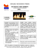
Figure 17 - PJD Control Valve
Piezo
Ignitor
Tab
Metalic
Core for
Manual
Ignition
Piezo Ignitor
ON/OFF Switch
Microswitch
MAN Knob
in Manual
Position
Motor
Knob
in ON
Position
Figure 18 - Pilot

www.desatech.com
111826-04C18
10. Continue holding down metal core for
about 10 seconds and then release the metal
core. Pilot should stay lit. If not, repeat steps
one through 4, page 17.
11. Turn MAN knob to ON position - main gas
ows.
12. Turn Motor-knob to adjust ame. Knob has
a slipping clutch that allows manual ame
height adjustment.
TO TURN GAS OFF
Press OFF button on remote control to switch
off main gas and pilot gas or manually turn
Motor-Knob clockwise to the "O" OFF
position.
Press to decrease the ame height and shut off
main burner.
INSPECTING BURNERS
Check pilot ame pattern and burner ame pat-
terns often.
Figure 19 shows a correct pilot ame pattern.
Figure 20 shows an incorrect pilot ame pattern.
The incorrect pilot flame is not touching the
thermocouple. When the thermocouple cools, the
heater will shut down.
If pilot ame pattern is incorrect, as shown in
Figure 20
• turn heater off (see To Turn Off Gas to Appli-
ance, above or page 17)
• see Troubleshooting, page 20
Note: The pilot ame on natural gas units will
have a slight curve, but ame should be blue and
have no yellow or orange color.
OPERATING HEATER
Continued
Thermocouple
Thermocouple
Figure 20 - Incorrect Pilot Flame Pattern
(Natural Gas Pilot Shown)
Figure 19 - Correct Pilot Flame Pattern
(Natural Gas Pilot Shown)
Figure 21 shows correct burner ame pattern.
If burner ame pattern is incorrect, as shown in
Figure 22
• turn appliance off (see To Turn Off Gas to Ap-
pliance in column 1 or page 17
• see Troubleshooting, page 20
Figure 21 - Correct Burner Flame Pattern
Figure 22 - Correct Burner Flame Pattern
Yellow Tipping
at Top of Blue
Flame

www.desatech.com
111826-04C 19
CLEANING AND
MAINTENANCE
WARNING: Turn off heater
-
The primary air inlet holes allow the proper amount
of air to mix with the gas. This provides a clean
burning ame. Keep these holes clear of dust, dirt,
lint and pet hair. Clean these air inlet holes prior to
each heating season. Blocked air holes will create
soot. We recommend that you clean the unit every
three months during operation and have heater
inspected yearly by a qualied service person.
We also recommend that you keep the burner tube
clean and free of dust and dirt. We recommend
using compressed air no greater than 30 PSI. Your
local computer store, hardware store or home
center may carry compressed air in a can. You can
use a vacuum cleaner in the blow position. If using
compressed air in a can, please follow the direc-
tions on the can. If you don't follow directions on
the can, you could damage the pilot assembly.
Before cleaning, shut off the unit, including the
pilot. Allow the unit to cool for at least thirty
minutes. You will need to remove the front log to
access the front burner.
1. Remove the two screws that hold the front log
bracket onto the assembly (see Figure 23). The
log is attached to this bracket. Gently lift up
on the log and bracket. Set aside.
2. Inspect burner and primary air inlet holes
on injector holder for dust and dirt (see
Figure 24).
3. Blow air through the ports/slots and holes in
the burner.
4. Check the injector holder located at the end
of the burner tube again. Remove any large
particles of dust, dirt, lint or pet hair with a
soft cloth or vacuum cleaner nozzle.
5. Blow air into the primary air holes on the
injector holder.
6. In case any large clumps of dust have now been
pushed into the burner repeat steps 3 and 4.
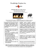
Figure 24 - Injector Holder on Front
Burner Tube
Burner Tube
Primary Air
Inlet Opening
Injector
Holder
Injector
Figure 23 - Removing Front Log to Clean
Front Burner
Front
Log

www.desatech.com
111826-04C20
TROUBLESHOOTING
Note: All troubleshooting items are listed in order of operation.
1. Ignitor electrode not con-
nected to ignitor cable
2. Ignitor cable pinched or wet
3. Broken ignitor cable
4. Bad piezo ignitor
5. Ignitor electrode positioned
wrong or broken
6. Bad module
1. Gas supply turned off or equip-
ment shutoff valve closed
2. Control knob not in PILOT
position
3. Control knob not pressed in
while in PILOT position
4. Air in gas lines when in-
stalled
5. Depleted gas supply (pro-
pane/LP only)
6. ODS/pilot is clogged
7. Gas regulator setting is not
correct
8. Bad module
1. Inlet gas pressure is too low
2. Burner orice(s) clogged
3. Burner orice(s) diameter is
too small
4. Wire disconnected from gas
control
5. Bad module
1. Manifold pressure is too low
2. Burner orice(s) clogged
When and are pressed
at the same time, there is no spark
at ODS/pilot
When and are pressed,
there is spark at ODS/pilot but
no ignition
Burner does not light after pilot
is lit
Delayed ignition burner
REMEDY
1. Reconnect ignitor cable
2. Free ignitor cable if pinched
by any metal or tubing. Keep
ignitor cable dry
3. Replace ignitor cable
4. Replace piezo ignitor
5. Replace pilot assembly
6. Replace module
1. Turn on gas supply or open
equipment shutoff valve
2. Turn control knob to PILOT
position
3. Press in control knob while in
PILOT position
4. Continue holding down con-
trol knob. Repeat igniting op-
eration until air is removed
5. Contact local propane/LP gas
company
6. Clean ODS/pilot (see Cleaning
and Maintenance, page 19) or
replace ODS/pilot assembly
7. Replace gas regulator
8. Replace module
1. Contact local natural or pro-
pane/LP gas company
2. Clean burner (see Cleaning
and Maintenance, page 19) or
replace burner orice(s)
3. Replace burner orice(s)
4. Reconnect leads (see Wiring
Diagram, page 24)
5. Replace module
1. Contact local natural or pro-
pane/LP gas company
2. Clean burner (see Cleaning
and Maintenance, page 19) or
replace burner orice
/