Frigidaire FGHF2344MF User manual
- Category
- Side-by-side fridge-freezers
- Type
- User manual

TABLE OF CONTENTS
www.frigidaire.com USA 1-800-944-9044 www.frigidaire.ca Canada 1-800-265-8352
All about the
Use & Care
of your Refrigerator
Important Safety Instructions ......................2
Features at a Glance ...................................4
Installation ................................................5
Door Removal Instructions ........................ 10
Installing Door Handles .............................13
Connecting Water Supply .......................... 17
Controls ...................................................19
Automatic Ice and Water Dispenser …………22
242134904 (June 2012)
Automatic Ice Maker - Freezer………………....24
Storage Features…………………………………….25
Storing Food and Saving Energy……………….29
Normal Operating Sounds and Sights………..30
Changing the Filter………………………………….31
Care and Cleaning…………………………………..33
Before You Call……………………………………….37
Major Appliance Warranty…………………………41

2
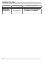
Doors
Handles are secure and tight
Door seals completely to cabinet on all sides
Freezer drawer is level across the top
Leveling
Refrigerator is level, side-to-side and tilted
¼” (6 mm) front-to-back
Toe grille is properly attached to refrigerator
Cabinet is setting solid on all corners
Electrical Power
House power turned on
Refrigerator plugged in
Ice Maker
House water supply connected to refrigerator
No water leaks present at all connections
- recheck in 24 hours
Ice maker is turned ON
Ice & water dispenser operates correctly
Final Checks
Shipping material removed
Fresh food and freezer temperatures set
Crisper humidity controls set
Registration card sent in
Installation Checklist
Denitions
This is the safety alert symbol. It is used to
alert you to potential personal injury hazards.
Obey all safety messages that follow this
symbol to avoid possible injury or death.
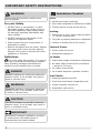
IMPORTANT SAFETY INSTRUCTIONS
For your Safety
• DO NOT store or use gasoline, or other
ammableliquidsinthevicinityofthisor
any other appliance. Read product labels
forwarningsregardingammabilityand
other hazards.
• DO NOT operate the refrigerator in the
presence of explosive fumes.
• Avoid contact with any moving parts of
automatic ice maker.
• Remove all staples from the carton. Staples
can cause severe cuts, and also destroy
nishesiftheycomeincontactwithother
appliances or furniture.
DANGER
DANGER indicates an imminently hazardous
situation which, if not avoided, will result in
death or serious injury.
WARNING
WARNING indicates a potentially hazardous
situation which, if not avoided, could result
in death or serious injury.
CAUTION
CAUTION indicates a potentially hazardous
situation which, if not avoided, may result in
minor or moderate injury.
IMPORTANT
IMPORTANT indicates installation, operation
or maintenance information which is
important but not hazard-related.
WARNING
Please read all instructions before using
this refrigerator.

3
IMPORTANT SAFETY INSTRUCTIONS
Child Safety
Destroy or recycle the carton, plastic bags, and
any exterior wrapping material immediately after
the refrigerator is unpacked. Children should
NEVER use these items to play. Cartons covered
with rugs, bedspreads, plastic sheets or stretch
wrap may become airtight chambers, and can
quicklycausesuffocation.
Risk of child entrapment
Child entrapment and suffocation are not
problems of the past. Junked or abandoned
refrigerators or freezers are still dangerous –
even if they will sit for “just a few days”. If you
are getting rid of your old refrigerator or freezer,
please follow the instructions below to help
prevent accidents.
Proper Disposal of Refrigerators/Freezers
We strongly encourage responsible appliance
recycling/disposal methods. Check with your utility
company or visit www.energystar.gov/recycle for
more information on recycling your old refrigerator.
Before you throw away your old refrigerator /
freezer:
• Remove
doors.
• Leave
shelves in
place so
children
may not
easily climb
inside.
• Have
refrigerant
removed by
aqualied
service
technician.
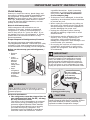
Electrical information
• The refrigerator must be plugged into its
own dedicated 115 Volt, 60 Hz., 15 Amp,
AC only electrical outlet.
Thepowercordoftheapplianceisequipped
with a three-prong grounding plug for your
protection against electrical shock hazards.
It must be plugged directly into a properly
grounded three prong receptacle. The
receptacle must be installed in accordance
with local codes and ordinances. Consult
aqualiedelectrician. Avoid connecting
refrigerator to a Ground Fault Interrupter
(GFI) circuit. Do not use an extension
cord or adapter plug.
• If the power cord is damaged, it should be
replaced by an authorized service technician
to prevent any risk.
• Never unplug the refrigerator by pulling on
thepowercord.Alwaysgriptheplugrmly,
and pull straight out from the receptacle to
prevent damaging the power cord.
• Unplug the refrigerator before cleaning
and before replacing a light bulb to avoid
electrical shock.
• Performance may be affected if the voltage
varies by 10% or more. Operating the
refrigeratorwithinsufcientpowercan
damage the compressor. Such damage is not
covered under your warranty.
• Do not plug the unit into an electrical outlet
controlled by a wall switch or pull cord to
prevent the refrigerator from being turned
off accidentally.
Grounding type wall receptacle
Do not, under
any circumstances,
cut, remove,
or bypass the
grounding prong.
Power cord with
3-prong gounded plug
CAUTION
To avoid personal injury or property damage,
handle tempered glass shelves carefully. Shelves
may break suddenly if nicked, scratched, or
exposed to sudden temperature change.
WARNING
These guidelines must be followed to ensure
that safety mechanisms in this refrigerator will
operate properly.
IMPORTANT
Pressing and holding the On/Off button for 3
seconds, located on the temperature control
panel, will disable your refrigerator’s cooling
system but does not disconnect the power to
the light bulb and other electrical components.
To turn off power to your refrigerator you must
unplug the power cord from the electrical outlet.

4
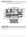
FEATURES AT A GLANCE
*Features may vary according to model
*Features may vary according to model
Ice Bin
*Fresh Food
Ice Maker
Flipper
Guide
*Incandescent Light
*LED
Light
Water
Filter
*Dairy
Compartmen
t
*Air Filter
®
SpillSafe
Shelves
Flipper
Mullion
Crisper
Drawer
*Door Bin
Freezer Baskets
Toe Grille
*Ice
Maker
Adjustable
Hinges
*Can Rack
SpillSafe
®
Shelves
Crisper
Drawer
TM
Store-
More
Drawer
IMPORTANT
Features not purchased with your refrigerator can be purchased at www.frigidaire.com or by
calling 1-800-944-9044.

5
Phillips™
Head or
#2 Square
Drive Head
(OR)
AND OR
Socket
Wrench Set
Adjustable
Wrench
OR
3/8"
Fixed
Wrench
Tools Necessary:
Top Hinge
Cover Front
Screw
Top Hinge
Cover Rear
Screw
Lower
Hinge
Screw
Top
Hinge
Screw
Components Provided:
INSTALLATION
This Use & Care Guide provides general
installation and operating instructions for
your model. We recommend using a service
or kitchen contracting professional to install
your refrigerator. Use the refrigerator only as
instructed in this Use & Care Guide. Before
starting the refrigerator, follow these
importantrststeps.
Location
• Choose a place that is near a grounded,
non-GFCI, electrical outlet. Do Not use an
extension cord or an adapter plug.
• If possible, place the refrigerator out of
direct sunlight and away from the range,
dishwasher, or other heat sources.
• Therefrigeratormustbeinstalledonaoor
that is level and strong enough to support
a fully loaded refrigerator.
• Consider water supply availability for models
equippedwithanautomaticicemaker.
Installation
• Allow the following clearances for ease
of installation, proper air circulation, and
plumbing and electrical connections:
Sides & Top
3
/
8
” (9.5 mm)
Back 1” (25.4 mm)
Door opening
Your refrigerator should be positioned to allow
easy access to a counter when removing
food. For best use of refrigerator drawers and
freezer baskets, the refrigerator should be in a
position where both can be fully opened.
Required Tools
You will need the following tools:
CAUTION
Do Not install the refrigerator where the
temperature will drop below 55°F (13°C) or
rise above 110°F (43°C). The compressor
will not be able to maintain proper
temperatures inside the refrigerator.
Do Not block the toe grille on the lower front
ofyourrefrigerator.Sufcientaircirculation
is essential for the proper operation of your
refrigerator.
NOTE
If your refrigerator is placed with the door
hinge side against a wall, you may have to
allow additional space so the door can be
opened wider.

6
INSTALLATION
Toe Grille Must
Fit in Slot On
Anti-tip Bracket
Screw/Washer
Assembly
(3) Retaining Clips
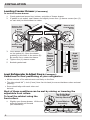
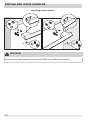
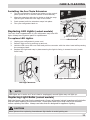
Leveling Freezer Drawer (if necessary)
To level the freezer drawer:
1. Check gasket seal around top, bottom, and sides of freezer drawer.
2. If gasket is not sealed, open drawer and slightly loosen four (4) drawer screws (two (2)
on each side) to allow drawer to rotate.
3. Close drawer and recheck the seal
on the gasket (A). Open the drawer
grabbing by the sides in the center (B).
Be careful not to rotate the drawer.
4. Tighten four (4) drawer screws.
5. Recheck gasket seal.
Level Refrigerator & Adjust Doors (if necessary)
Guidelinesfornalpositioningofyourrefrigerator:
• Allfourcornersofthecabinetmustrestrmlyontheoor.
• The sides should tilt
1
/
4
inch (6 mm) from front to back (to ensure that doors close and seal
properly).
• Doors should align with each other and
be level.
Most of these conditions can be met by raising or lowering the
adjustable front rollers.
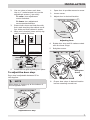
To level the cabinet using the
front rollers:
1. Slightly open freezer drawer. Lift the toe
grille and gently pull forward
(see illustration).
Grab
Drawer
at
Center
from
Both
Sides
then
Pull
Drawer
Out
Push
Against
Freezer
Drawer
A B
Remove Hex
Head Drawer
Screw
Remove Hex
Head Drawer
Screw
Do Not Remove
Other Screws
Remove Hex
Head Drawer
Screw
Do Not Remove
Other Screws
Remove Hex
Head Drawer
Screw

7
NOTE
View shown is looking up at the bottom of
the refrigerator door.
2. You can raise or lower each door.
Use a
3
/
8
” socket wrench to turn the
adjustment screws (1 per side).
To raise: turn adjustment
screw clockwise.
To lower: turn adjustment
screw counterclockwise.
3. Ensure both doors are bind-free with
their seals touching the cabinet on all
four sides and that cabinet is stable.
4. After unit is leveled, lower anti-tip leg
untilitcontactstheoor.
Raise
Anti-tip
Leg
Door
Lower
Door
5. Installthetoegrillebyttingintoplace.
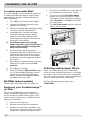
To adjust the door stop:
Door stop is adjustable between 85 to
145 degrees.
1. Open door to provide access to screw.
2. Loosen screw.
3. Adjust door to desired location.
4. Rotate door stop until it makes contact
with the lower hinge.
5. Retighten screw.
6. Ensure door stops in desired location
before resuming normal use.
Rotate
Door to Desired
Location
Adjusting Door
Rotate
Door
Stop
Re-tighten
Screw
Retighten Screw
Adjustable Door Stop
Lower
Hinge
Door
Stop
Screw
Min
Open
Max
Open
INSTALLATION

8
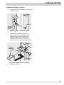
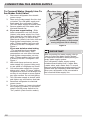
NOTE
If after adjusting doors higher the door makes
a popping/clicking sound, remove screw and
replace with the longer one supplied in the
handle package (select models).
4. Lift the door while adjusting the
washer. To raise the door, rotate
washer clockwise (when viewed from
the bottom). To lower door, rotate
washer counterclockwise (when viewed
from the bottom).
5. Retighten the screw (where applicable),
ensuring it is between the spokes of the
washer. Screw will not be tight, just
insertuntilitisushwiththehinge.
Door
Lower
Door
Hinge
Washer
Raise
Door
Raising/Lowering Door
Screw (where applicable)
Hinge
Washer Spokes
Screw
Retighten Screw
INSTALLATION
To level the doors using the
adjustable lower hinge
(select models):
1. Remove all food items from door bins
on door being adjusted.
2. Open doors to 90 degrees.
3. Loosen or remove screw.
NOTE
Adjustable hinge should only be used after
doors have been leveled with rollers.
A
B
Loosen or Remove
Screw
Open
Door
90
Degrees
Bottom of Door
Loosen/Remove Screw (where applicable)

9
Flipper
Mullion
Hinge
Screw
Flipper
Mullion
Adjusting Flipper Mullion Screw
Toadjusttheippermullion:
1. Loosenthescrewlocatedontheipper
mullion hinge.
2. Adjustippermullionheight.For
properconnectionwiththeipper
mullion guide, there should be a
separation about the thickness of
a coin (0.060 inches, or 1.5 mm)
betweentheguideandippermullion.
Mullion
Guide
Flipper
Mullion
Thickness
of a Coin
Adjusting Flipper Mullion Height
3. Retighten screw.
INSTALLATION

10
NOTE
DO NOT remove the ground screw from hinge.
NOTE
Use care while pulling the water tube from the
unit to be sure you do not kink the tube.
Press
Press
Water
Line
Approximately
5 Feet
DOOR REMOVAL INSTRUCTIONS
To remove the refrigerator doors:
1. Trace lightly around the door’s top
hinges with a pencil. This makes
reinstallation easier.
2. Disconnect the harness by grasping both
sidesoftheconnectorrmly,depressthe
latch, and pull apart. Remove the two (2)
screws from the top hinge. Lift the door
off of the bottom hinge and set it aside.
3. Detach the water tube from the
connector located behind the
refrigerator and pull the tube back out
to the front of the unit. The connector
releases when you press inward on
the outer sleeve while pushing the
tube toward the connector then while
continuing to hold in the sleeve, pull
the tube away.
Getting through narrow spaces
Ifyourrefrigeratorwillnottthroughan
entrance area, you can remove the doors.
Checkrstbymeasuringtheentrance.
To prepare for removing the doors:
1. Make sure the electrical power cord is
unplugged from the wall outlet.
2. Open the freezer drawer and remove
the toe grille (see “Installation” section).
3. Remove any food from the door
shelves and close the doors.
To remove the top hinge covers:
1. Remove the two (2) screws from each
cover over the top door hinges.
2. Lift inside edge of hinge cover and
tilt back.

11
NOTE
Youwillbepullingapproximatelyve(5)feetofwatertubefromthebackoftherefrigerator.
NOTE
When reinserting the water tube and replacing the top hinge cover, use care to be sure you do not
kink the tube.
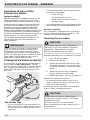
DOOR REMOVAL INSTRUCTIONS
Once both doors are in place, ensure they are aligned with each other and level (Please see the
“Installation” section for more details), and replace the top hinge cover.
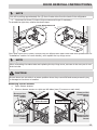
4. Unscrew the three (3) lower hinge screws and hinge if necessary.
To reinstall the right door, reverse the above steps.
Removing Freezer Drawer
1. Open freezer drawer.
2. Remove drawer screws on right and left sides (two (2) screws on each side).
CAUTION
Be sure doors are set aside in a secure position where they cannot fall and cause personal injury,
or damage to the doors or handles.
Remove Hex
Head Drawer
Screw
Remove Hex
Head Drawer
Screw
Do Not Remove
Other Screws
Lower Hinge Removal
Remove Hex
Head Drawer
Screw
Do Not Remove
Other Screws
Remove Hex
Head Drawer
Screw

12
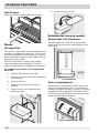
DOOR REMOVAL INSTRUCTIONS
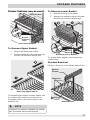
NOTE
Do not remove center screw from freezer
drawer. This is a factory adjustment.
CAUTION
Drawer is heavy. Use caution when lifting.
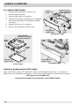
1. Lift drawer up and out to remove.
Installing Freezer Drawer
1. With lower slides pulled out, hang
drawer onto slide brackets ensuring
pins on each side are fully inserted into
slots on each side.
2. Reinstall four (4) drawer screws (two
(2) per side), tighten down, and close
drawer (C).
3. Check gasket seal around top, bottom,
and sides of freezer drawer.
4. If gasket is not sealed, open drawer
and slightly loosen four (4) drawer
screws (two (2) on each side) to allow
drawer to rotate.
5. Close drawer and recheck the seal
on the gasket (A). Open the drawer
grabbing by the sides in the center (B).
Be careful not to rotate the drawer.
Assembly
Pin
Slot
Cabinet
Drawer
Fully Extend
Drawer Slides
Install
Screws
(2) Each
Side
Grab
Drawer
at
Center
from
Both
Sides
then
Pull
Drawer
Out
Push
Against
Freezer
Drawer
6. Tighten four (4) drawer screws.
7. Recheck gasket seal.
8. Installthetoegrillebyttinginto
place.

13
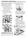
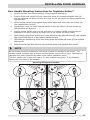
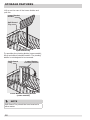
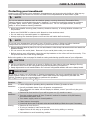
NOTE
All set screws should be tightened so the screw is below the surface of the handle. The
handles should be drawn tight to freezer and refrigerator doors with no gaps. Opening the
opposite door while tightening the Allen screw makes installation easier.
The door handle may loosen over time or if it was installed improperly. If this happens,
tighten the set screws on the handles.
INSTALLING DOOR HANDLES
Door Handle Mounting Instructions for Frigidaire Gallery
®
1. Remove handles from carton and any other protective packaging.
2. Position fresh food handle end over upper and lower pre-installed shoulder bolts (A)
that are fastened into door, ensuring the holes for the set screws are facing towards the
opposite door.
3. Whileholdinghandlermlyagainstdoor,fastenupperandlowerAllensetscrews(B)
with supplied Allen wrench.
4. Repeat steps 2 and 3 to install opposite handle. Ensure the holes for the set screws are
facingtowardstherstdoor.
5. Position freezer handle end over left and right pre-installed handle mounts that are
fastened to the door, ensuring the holes for the set screws are facing down.
6. Whileholdinghandlermlyagainstdoor,looselytightenfarrightAllensetscrew(B)withsupplied
Allen wrench until there is no gap between handle and door.
7. Stillholdingthehandlermlytothedoor,rmlytightenfarleftAllensetscrew(B)withsupplied
Allen wrench.
8. ReturntothefarrightAllensetscrew(B)andrmlytightenwithsuppliedAllenwrench.
Mounting Refrigerator Handles

14
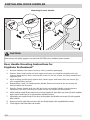
Door Handle Mounting Instructions for
Frigidaire Professional
®
1. Remove handles from carton and any other protective packaging.
2. Position fresh food handle end over upper and lower pre-installed shoulder bolts (A)
that are fastened into door, ensuring the holes for the set screws are facing towards the
opposite door.
3. Whileholdinghandlermlyagainstdoor,fastenupperandlowerAllensetscrews(B)
with supplied Allen wrench.
4. Repeat steps 2 and 3 to install opposite handle. Ensure the holes for the set screws are
facingtowardstherstdoor.
5. Position freezer handle end over left and right pre-installed handle mounts that are
fastened to the door, ensuring the holes for the set screws are facing down.
6. Whileholdinghandlermlyagainstdoor,looselytightenfarrightAllensetscrew(B)withsupplied
Allen wrench until there is no gap between handle and door.
7. Stillholdingthehandlermlytothedoor,rmlytightenfarleftAllensetscrew(B)withsupplied
Allen wrench.
8. ReturntothefarrightAllensetscrew(B)andrmlytightenwithsuppliedAllenwrench.
9. Firmly tighten the inside Allen set screws.
INSTALLING DOOR HANDLES
Mounting Freezer Handle
CAUTION
Wear gloves and safety goggles. Use extreme CAUTION when installing these handles.

15
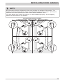
NOTE
All set screws should be tightened so the screw is below the surface of the handle. The
handles should be drawn tight to freezer and refrigerator doors with no gaps. Opening the
opposite door while tightening the Allen screw makes installation easier.
The door handle may loosen over time or if it was installed improperly. If this happens,
tighten the set screws on the handles.
INSTALLING DOOR HANDLES
Mounting Refrigerator Handles

16
Mounting Freezer Handle
CAUTION
Wear gloves and safety goggles. Use extreme CAUTION when installing these handles.
INSTALLING DOOR HANDLES

17
NOTE
Check with your local building authority
for recommendations on water lines and
associated materials prior to installing your
new refrigerator. Depending on your local/
state building codes, Frigidaire recommends for
homes with existing valves its Smart Choice
®
water line kit 5305513409 (with a 6 ft. Stainless
Steel Water Line) and for homes without an
existing valve, Frigidaire recommends its Smart
Choice
®
water line kit 5305510264 (with a 20
ft. Copper Water Line with self-tapping saddle
valve). Please refer to www.frigidaire.com/
store for more information.
CONNECTING THE WATER SUPPLY
Before Installing The Water
Supply Line, You Will Need:
• BasicTools:adjustablewrench,at-blade
screwdriver, and Phillips
TM
screwdriver
• Access to a household cold water line with
water pressure between 30 and 100 psi.
• A water supply line made of ¼ inch (6.4
mm) OD, copper or stainless steel tubing.
To determine the length of tubing needed,
measure the distance from the ice maker
inlet valve at the back of the refrigerator
to your cold water pipe. Then add
approximately 7 feet (2.1 meters), so the
refrigerator can be moved out for cleaning
(as shown).
• A shutoff valve to connect the water supply
line to your household water system. DO
NOT use a self-piercing type shutoff valve.
• Donotreusecompressionttingoruse
thread seal tape.
• A compression nut and ferrule (sleeve) for
connecting a copper water supply line to the
ice maker inlet valve.
WARNING
To avoid electric shock, which can
cause death or severe personal injury,
disconnect the refrigerator from
electrical power before connecting a
water supply line to the refrigerator.
CAUTION
To Avoid Property Damage:
• CopperorStainlessSteelbraided
tubing is recommended for the water
supply line. Water supply tubing made
of ¼ inch plastic is not recommended
to be used. Plastic tubing greatly
increases the potential for water leaks,
and the manufacturer will not be
responsible for any damage if plastic
tubing is used for the supply line.
• DONOTinstallwatersupplytubingin
areas where temperatures fall
below freezing.
• Chemicalsfromamalfunctioning
water softener can damage the ice
maker. If your home has a water
softening system, ensure the softener
is maintained and working properly.
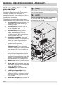
IMPORTANT
Ensure that your water supply line connections
comply with all local plumbing codes.

18
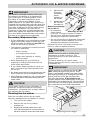
CONNECTING THE WATER SUPPLY
Figure 1
To Connect Water Supply Line To
Ice Maker Inlet Valve
1. Disconnect refrigerator from electric
power source.
2. Place end of water supply line into sink
or bucket. Turn ON water supply and
ushsupplylineuntilwaterisclear.
Turn OFF water supply at shutoff valve.
3. Remove plastic cap from water valve
inlet and discard cap.
4. If you use copper tubing - Slide
brass compression nut, then ferrule
(sleeve) onto water supply line. Push
water supply line into water valve inlet
as far as it will go (¼ inch/6.4 mm).
Slide ferrule (sleeve) into valve inlet and
ngertightencompressionnutonto
valve. Tighten another half turn with
a wrench; DO NOT overtighten. See
Figure 1.
If you use stainless steel tubing
- The nut and ferrule are already
assembled on the tubing. Slide
compression nut onto valve inlet and
ngertightencompressionnutonto
valve. Tighten another half turn with
a wrench; DO NOT overtighten. See
Figure 1.
5. With steel clamp and screw, secure
water supply line (copper tubing only)
to rear panel of refrigerator as shown.
6. Coil excess water supply line (copper
tubing only), about 2½ turns, behind
refrigerator as shown and arrange coils
so they do not vibrate or wear against
any other surface. Do not kink tubing.
7. Turn ON water supply at shutoff valve
and tighten any connections that leak.
8. Reconnect refrigerator to electrical
power source.
9. To turn ice maker on, lower wire signal
arm (freezer ice maker) or set the ice
maker’s On/Off power switch to the
“On” position (fresh food ice maker).
Steel
Clamp
Brass
compression
Nut
Ferrule
(Sleeve)
Water
line
Water Valve
Bracket
Valve Inlet
Water Valve
Water line from
household water
supply
(Include enough tubing on loop to allow
moving refrigerator out for cleaning.)
Plastic Water Tubing
to Ice Maker
Fill Tube
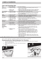
IMPORTANT
After connecting the water supply, refer to
“How to Prime the Water Supply System”
for important information about priming an
empty water supply system.
Your refrigerator’s water supply system
includesseveraltubinglines,awaterlter,
a water valve, and a water tank. To ensure
that your water dispenser works properly, this
systemmustbecompletelylledwithwater
whenyourrefrigeratorisrstconnectedto
the household water supply line.

19
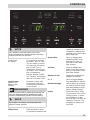
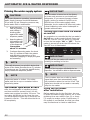
CONTROLS
(Fresh Food
Ice Maker)
(Freezer Ice
Maker, select
models)
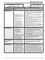
ice off Press and hold for three
(3) seconds to turn the
ice maker “ON” or “OFF”.
The ice maker is turned
off when the LED above
the “Ice Off” icon is
illuminated. Turning the
ice maker “OFF” disables
the ice dispensing
feature. Neither “CUBE”
nor “CRUSH” will operate
with the ice maker “OFF”.
quick freeze Activates a faster rate
for freezing food and
increases ice production
in the freezer.
light On / Off
control lock Press and hold for three
(3) seconds to activate and
deactivate. This restricts
undesired changes to the
refrigerator’s settings and
prevents use of the ice and
water dispenser.
waterlter Touchtodisplaylter
condition status. Press
and hold for three (3)
seconds to reset after
lterchange.
airlter Touchtodisplaylter
status. Press and hold for
three (3) seconds to reset
afterlterchange.
display on-off Toggles the temperature
displays On and Off.
C / F Touch to toggle display
from Fahrenheit to Celsius.
default settings Hold to Reset all refrigera-
tor settings such as temp,
and temp display to their
factory default settings.
power Press and hold for three
(3) seconds to turn off the
cooling system to clean
the refrigerator. It also
turns off the ice maker, all
dispenser functions. The
temperature display will
read OFF.
NOTE
Your appliance may have some or all of the
features listed below. Become familiar with these
features and their use and care.
NOTE
For freezer ice maker, see Automatic Ice
Maker-Freezer section.
IMPORTANT
When the fresh food ice maker is turned off, the
ice in the bucket should be transferred to the
freezer or discarded to prevent it from melting.

20
Yourrefrigeratorisequippedwithatouch control
panel. It is only necessary to gently touch the
control panel. There are three (3) dispenser modes:
1. Water
2. Ice Cubes
3. Crushed Ice
A green indicator light will be illuminated above
the active feature.
CONTROLS
Alarms
Door Ajar If the door has been left
open for an extended pe-
riod of time, an alarm will
sound and the door ajar
indicator will illuminate
on the display. Press the
alarm reset key to reset
any system alarms.
High Temp In the event of a high
temperature condition,
the temperature display
will blink and display “HI”.
After 20 minutes, the
high temp alert will be
illuminated. Press alarm
reset to acknowledge
the alarm, at which time
the highest temperature
reached will be displayed
and the refrigerator will
resume normal opera-
tion. All other modes are
turned off until the alarm
is acknowledged.
Power Fail In the event of a power
failure, the power fail
alert will be illuminated.
Press alarm reset to
Setting cooling temperatures
1. Down (∨) and Up (∧) indicators are located
beside the displayed temperatures.
2. Press the ∨ or ∧ indicator to adjust the
temperature to the desired setting.
3. The temperature display will begin to
blinkwiththersttouch.Afterve(5)
seconds of inactivity, the display will beep
to accept the new temperature. After 10
seconds, the display times out and returns
to the basic display.
Sabbath Mode
The Sabbath Mode is a feature that disables portions
of the refrigerator and its controls in accordance
with observance of the weekly Sabbath and religious
holidays within the Orthodox Jewish community.
Sabbath Mode is turned ON and OFF by pressing
and holding both the freezer “∨” and refrigerator “∧”
indicatorsforve(5)seconds.Thedisplayshows
“Sb” while in Sabbath mode.
In the Sabbath Mode, the High Temp alarm is
active for health reasons. If a high
temperature alarm is activated during
this time, for example due to a door left
ajar, the alarm will sound intermittently
for about 10 minutes. The alarm will then silence
on its own and a red high temperature icon will
display. The high temp icon will continue to display,
even if the door is closed, until the Sabbath mode
is exited and the icon reset. The refrigerator will
function normally once the door is closed, without
any violation of the Sabbath/Holidays.
For further assistance, guidelines for proper usage
and a complete list of models with the Sabbath
feature, please visit the web at http:\\www.
star-k.org.
acknowledge the alarm.
Other modes may be
turned off until the alarm
is acknowledged. When
the power fail alert
is acknowledged, the
refrigerator will resume
normal operation. The
high temp alarm may also
be illuminated until a safe
operating range tempera-
ture has been reached.
NOTE
While in Sabbath Mode, neither the lights,
dispenser, nor the control panel will work until
Sabbath Mode is deactivated.
Refrigerator stays in Sabbath Mode after power
failure recovery. It must be deactivated with
the buttons on the control panel.
NOTE
Although you have entered the Sabbath
Mode, the ice maker will complete the
cycle it had already initiated. The ice cube
compartment will remain cold and new ice
cubes can be made with standard trays.
IMPORTANT
Pressing the power on/off icon does not turn
off power to your refrigerator. You must unplug
the power cord from the wall outlet.
Page is loading ...
Page is loading ...
Page is loading ...
Page is loading ...
Page is loading ...
Page is loading ...
Page is loading ...
Page is loading ...
Page is loading ...
Page is loading ...
Page is loading ...
Page is loading ...
Page is loading ...
Page is loading ...
Page is loading ...
Page is loading ...
Page is loading ...
Page is loading ...
Page is loading ...
Page is loading ...
Page is loading ...
-
 1
1
-
 2
2
-
 3
3
-
 4
4
-
 5
5
-
 6
6
-
 7
7
-
 8
8
-
 9
9
-
 10
10
-
 11
11
-
 12
12
-
 13
13
-
 14
14
-
 15
15
-
 16
16
-
 17
17
-
 18
18
-
 19
19
-
 20
20
-
 21
21
-
 22
22
-
 23
23
-
 24
24
-
 25
25
-
 26
26
-
 27
27
-
 28
28
-
 29
29
-
 30
30
-
 31
31
-
 32
32
-
 33
33
-
 34
34
-
 35
35
-
 36
36
-
 37
37
-
 38
38
-
 39
39
-
 40
40
-
 41
41


Frigidaire FGHF2344MF User manual
- Category
- Side-by-side fridge-freezers
- Type
- User manual
Ask a question and I''ll find the answer in the document
Finding information in a document is now easier with AI
Related papers
-
Frigidaire FGHB2866PF User manual
-
Frigidaire DGHF2360PF User manual
-
Frigidaire FGHB2866PP User manual
-
Frigidaire FPBC2277RF Owner's manual
-
Frigidaire LFHG2251TF Owner's manual
-
Frigidaire FFHD2250TS User manual
-
Frigidaire FFHB2750TP User guide
-
-
Frigidaire FFHB2750TS User guide
-
Frigidaire FFHB2750TE User manual
Other documents
-
Electrolux EI28BS56IW0 Owner's manual
-
-
-
-
Heartland HCFDR23BLK HCFDR23 owners guide
-
-
-
Crosley CFD28WIQWC Owner's manual
-
Electrolux EI23BC56IW6 Owner's manual
-
Frigidaire Professional 1089565 User guide