Page is loading ...

SCP-2R
Manual Call Point
General Description
SCP-2R is a manual call point, designed to work with conventional fire panels.
Functional specifications
Standard. . . . . . . . . . . . . . . EN 54-11
Type (according EN 54-11) . A
Frangible element type . . . . resettable (flexible)
Indication “Fire alarm” . . . . red LED
Material (plastic), color . . . . ABS, red
Working Principle
In stand-by mode, the resettable call point element is in the middle position. The call point LED is off.
When the element is pressed, the resettable element will move down and a color strip will now be displayed at the top of the
element. The call point LED will now be illuminated - this will generate a “Fire alarm” condition.
The resetting of the flexible element back to the stand-by mode is done with the special key/ tool - Place the long side of the tool
into the slot on the SCP-2R bottom edge with the word UP facing you and push up until flexible element moves up to the middle
position (a click will be heard).
Installation Instructions
Remove the cover by means of the three prong key being inserted in the holes at the top of the SCP-2R.
Remove and take out the element by means of the key, using the long side with the word UP facing you. Inserted the key
between the bottom of the element and the carrier/red case. Remove the flexible element from the carrier unit by lifting the
element at the bottom away from the carrier and side the element down and pull out.
Keep the element in a safe place.
The SCP-2R can be surface fitted or flush mounted.
Surface mounting
1. Mount the back box and observe the knockout holes - never locate the knockouts on the left or right side.
2. With the cover and element removed connect cables as required to the terminals (see the connection diagram).
3. Place the carrier unit over the back box and use the supplied screws to secure the carrier to the back box.
4. Refit flexible element to the carrier unit.
5. Refit the cover by locating the
bottom of the cover first then pushing the top back/clip into position.
6. Test the call point functionality and reset.
Flush mounting
The flush mounting of SCP-2R call point can be fitted into a standard UK single gang back box with a depth of 25mm or greater.
The fitting/asembling and wiring of the SCP-2R flush fitting is the same as for the surface mount fitting.
Testing the Call Point Operation
Isolate/put into test mode the fire alarm system before testing. Use the special tool to test the call point operation. To carry out
the test - insert the long part of the key/tool with the word UP facing you into the “Test” hole. This is located at the bottom of the
SCP-2R and push up to test. The tool will move the flexible element up and thus operates the call point.
The LED will illuminate while the call point is in test mode. To end the test remove the tool/key from the SCP-2R, the LED will go
out and the call point will be reset.
Technical specifications
Operating voltage . . . . . . . . . . . . . . 9 ÷ 30 VDC
Nominal operating voltage . . . . . . . . 24 VDC
Current consumption in alarm state . 23mA/15V; 38mA/24V; 48mA/30V
2 2
Installation wires . . . . . . . . . . . . . . . 0,4mm ÷ 2.0mm
Relative humidity . . . . . . . . . . . . . . . ≤93% @ +40°C
90mm
90mm
56mm
Dimensions
!
Manufacturer: Teletek Electronics JSC
Address: 14A Srebarna Str, 1407 Sofia, Bulgaria
Http://www.teletek-electronics.com
Installation Instructions
IP40
-10°C ÷ +60°C
≤150g
Installation
!
Distributor: Elite Security Products Ltd, Unit 7
Target Park, Shawbank Road Lakeside,
Redditch B98 8YN, UK
http://www.espuk.com
1293-CPD-0161

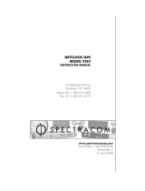
STRUCTURE
+
-
+
-
CONTENTS:
(1) - surface mounting box;
(2) - carrier unit;
(3) - PCB with terminals (mounted on the back
of the carrier unit);
(4) - resettable (flexible) element;
(5) - cover;
(6) - tool for opening, testing and resetting of
the flexible element in stay-by mode (use the
tool as shown on the picture - the “UP” mark
must be in front).
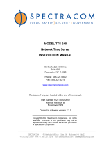
Connection to a fire panel
Fire Alarm Panel
SCP-2R SCP-2R
EOL
IN OUT
IN OUT
Surface and flush
mounting position
LED Indication
Stand-by mode
Alarm mode
Test mode
Testing the operation
The “UP” mark on the
key must be to the front
(facing you)
Push upwards - the
LED will come on.
18020641
/