Robe Robin Strobe User manual
- Category
- Stroboscopes & disco lights
- Type
- User manual

1
Version 1.5

2
Table of contents
1. Safety instructions ......................................................................................................... 3
2. Fixture exterior view ...................................................................................................... 5
3. Installation....................................................................................................................... 6
3.1 Connection to the mains ............................................................................................ 6
3.2 Installing the gel frame and barndoors ....................................................................... 7
3.3 Rigging the xture and oor installation of the xture ................................................ 8
3.4 DMX-512 connection ................................................................................................ 13
3.5 Ethernet connection ................................................................................................. 14
4. Control menu map ........................................................................................................ 16
5. DMX chart ...................................................................................................................... 18
6. Strobe and Special eects running ........................................................................... 20
6.1 Strobe ...................................................................................................................... 20
6.2 Special eects ......................................................................................................... 20
7. Control menu ............................................................................................................... 22
7.1 Tab " Address" .......................................................................................................... 23
7.2 Tab "Information" ...................................................................................................... 24
7.3 Tab "Personality" ...................................................................................................... 25
7.4 Tab "Manual Control" ................................................................................................ 26
7.5 Tab "Stand-alone" .................................................................................................... 26
7.6 Tab "Service" ............................................................................................................ 27
8. RDM ............................................................................................................................... 28
9. Wireless DMX operation .............................................................................................. 28
10. Error and information messages .............................................................................. 29
11. Technical Specications ............................................................................................ 30
12. Maintenance and cleaning ......................................................................................... 32
12.1 Replacing fuse ....................................................................................................... 33
12.2 Disposing of the product ........................................................................................ 33
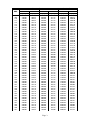
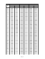
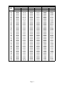
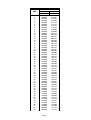
13. Appendix ..................................................................................................................... 33
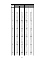
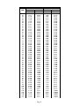
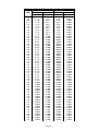
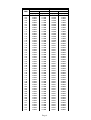
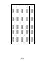
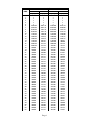
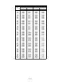
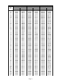
13.1 Strobe and Special eects timing .......................................................................... 33
Robin Strobe

3
FOR YOUR OWN SAFETY, PLEASE READ THIS USER MANUAL CAREFULLY
BEFORE POWERING OR INSTALLING YOUR ROBIN Strobe !
Save it for future reference.
This device has left our premises in absolutely perfect condition. In order to maintain this condition and to en-
sure a safe operation, it is absolutely necessary for the user to follow the safety instructions and warning notes
written in this manual.
The manufacturer will not accept liability for any resulting damages caused by the non-observance of this ma-
nual or any unauthorized modication to the device.
Please consider that damages caused by manual modications to the device are not subject to warranty.
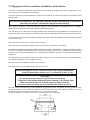
The Robin Strobe was designed mainly for indoor use and it is intended for
professional applications only. It is not for household use.
1. Safety instructions
DANGEROUS VOLTAGE CONSTITUTING A RISK OF ELECTRIC SHOCK IS PRESENT WITHIN THIS UNIT!
Make sure that the available voltage is not higher than stated on the rear panel of the xture.
This xture should be operated only from the type of power source indicated on the marking label. If you are
not sure of the type of power supplied, consult your authorized distributor or local power company.
WARNING! This unit does not contain an ON/OFF switch. Always disconnect power input cable to completely
remove power from unit when not in use or before cleaning or servicing the xture.
The power plug has to be accessible after installing the xture. Do not overload wall outlets and extension cords
as this can result in re or electric shock.
Do not allow anything to rest on the power cord. Do not locate this xture where the cord may be damaged by
persons walking on it.
Make sure that the power cord is never crimped or damaged by sharp edges. Check the xture and the power
cord from time to time.
Refer servicing to qualied service personnel.
This xture falls under protection class I. Therefore this xture has to be connected to
a mains socket outlet with a protective earthing connection.
Do not connect this xture to a dimmer pack.
Warning!
LED light emission. Risk of eye injury. Do not look into the beam at short distance of
the of the product. Do not view the light output with optical instruments or any device
that may conncentrate the beam
To guard against epileptic seizure:
Do not operate the xture near stairways. Provide advance notice that strobe lighting
is in use. Avoid extended periods of continuous ashing, particularly at frequencies of
10 to 20 ashes per second
If the xture has been exposed to drastic temperature uctuation (e.g. after transportation), do not switch it on

4
immediately. The arising condensation water might damage your device. Leave the device switched o until
it has reached room temperature.
Do not shake the xture. Avoid brute force when installing or operating the xture.
When choosing the installation spot, please make sure that the xture is not exposed to extreme heat, moisture
or dust.
Air vents and slots in the xture are provided for ventilation, to ensure reliable operation of the device and to
protect it from overheating.The openings should never be covered with cloth or other materials, and never
must be blocked.
This xture should not be placed in a built-in installation unless proper ventilation is provided.
Never place lters or other materials over the front glass cover.
Only operate the xture after having checked that the housing is rmly closed and all screws are tightly fastened.
To avoid damage of the internal optical system of the xture, never let the sunlight
lights directly to the lens array, even when the xture is not working !
Keep ammable materials well away from the xture.
Do not illuminate surfaces within 1 meter of the xture.
Provide a minimum clearance of 0.3 meters around air vents
Always use a secondary safety cable when rigging this xture.
Make sure that the area below the installation place is blocked when rigging, derigging or servicing the xture.
The xture becomes very hot during operation. Allow the xture to cool approximately 20 minutes prior to ma-
nipulate with it.
Operate the xture only after having familiarized with its functions. Do not permit operation by persons not
qualied for operating the xture. Most damages are the result of unprofessional operation!
Please use the original packaging if the xture is to be transported.
Please consider that unauthorized modications on the xture are forbidden due to safety reasons!
If this device will be operated in any way dierent to the one described in this manual, the product may suer
damages and the guarantee becomes void. Furthermore, any other operation may lead to dangers like short-
-circuit, burns, electric shock, crash etc.

5
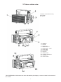
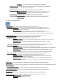
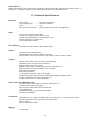
2. Fixture exterior view
4 - Antenna
5 - DMX IN
6 - DMX OUT
7 - Control buttons
8 - QVGA touch screen
9 - Fuse holder
10 - RJ 45 Input
11 - Power In
12 - Safety screw
13 - Locking mechanism
14 - Safety lock
15 - Screen cover
1 - Glass cover and lens array
2 - U-holder
3 - Tilt lock
The ENTER/DISPLAY ON button also serves for switching the display on when the xture is disconnected
from mains.

6
3. Installation
Fixtures must be installed by a Qualied electrician in accordance with all
national and local electrical and construction codes and regulations.
3.1 Connection to the mains
For protection from electric shock, the xture must be earthed!
The Robin Strobe is equipped with auto-switching power supply that automatically adjusts to any 50-60Hz AC
power source from 100-240 Volts.
Connect the xture to the mains by means of the enclosed power cord
If you need to install other plug on the power cord, note that the cores in the power cord are coloured according
to the following table. The earth has to be connected!
If you have any doubts about proper installation, consult a qualied electrician.
Core (EU) Core (US) Connection Plug Terminal Marking
Brown Black Live L
Light blue White Neutral N
Yellow/Green Green Earth
Do not overload the supply line and the connecting leads.
Wiring and connection work must be carried out by qualied sta!

7
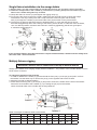
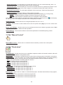
3.2 Installing the gel frame and barndoors
Disconnect the xture from mains before the accessory installation.
Never operate the xture with barndoors closed.
1. Put the frame adaptor (1) on the xture and
secure it with four screws (2).
2. Insert the gel frame (4) into slots (3) of
the frame adaptor (1). Use the slots closer to
the glass cover of the xture.
3. Insert the barndoors (5) into second slots (3) of
the frame adaptor (1).
4. Secure inserted barndoors and (or) the gel
frame by means of the two locks (6).
Lift up a little the lock (6) to release it from
the projection (7) and move it to the position
as shown on the picture B until the projection (8)
snaps into lock (6).
Do not operate the xture with unsecured gel
frame or barndoors!

8
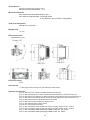
3.3 Rigging the xture and oor installation of the xture
A structure intended for installation of the xture (s) must safely hold weight of the xture(s) placed on it. The
structure has to be certicated to the purpose.
The xture (xtures) must be installed in accordance with national and local electrical and construction codes
and regulation..
For overhead installation, the xture(s) must be always secured with a safety wire
that can bear at least 10 times the weight of the xture(s).
When rigging, derigging or servicing the xture staying in the area below the installation place, on bridges,
under high working places and other endangered areas is forbidden.
The operator has to make sure that safety-relating and machine-technical installations are approved by an
expert before taking into operation for the rst time and after changes before taking into operation another time.
The operator has to make sure that safety-relating and machine-technical installations are approved by a skilled
person once a year.
Allow the xture to cool for ten minutes before handling.
The xture should be installed outside areas where persons may walk by or be seated.
IMPORTANT! OVERHEAD RIGGING REQUIRES EXTENSIVE EXPERIENCE, including calculating working
load limits, installation material being used, and periodic safety inspection of all installation material and the
projector. If you lack these qualications, do not attempt the installation yourself, but use a help of professional
companies.
CAUTION: Fixtures may cause severe injuries when crashing down! If you have doubts concerning the safety
of a possible installation, do not install the xture!
The xture has to be installed out of the reach of public.
The xture must never be xed swinging freely in the room.
When installing the device, make sure there is no highly inammable
material (decoration articles, etc.) in a distance of min. 0.5 m.
CAUTION!
Use an appropriate clamp to rig the xture on the truss.
Follow the instructions mentioned at the bottom of the xture base.
Make sure that the device is xed properly! Ensure that the
structure (truss) to which you are attaching the xture is secure.
The xture can be placed directly on the stage oor or rigged to the truss. The xture can be rigged to the truss
via Omega holder and one clamp (two holes with 140mm spacing serve for this method of mounting) or using
stacker which allows 2-6 xtures connected in the top-to-bottom method.
For oor installation use a oor stand if two or more xtures are to be stacked
.

9
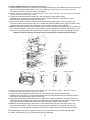
Single xture installation via the omega holder
1. Bolt the clamp (1) to the omega holder (2) with M12 bolt and lock nut through the hole in the holder.
2. Fasten the omega holder to the U-holder (4) of the xture by inserting both quick-lock fasteners (3) into
holes in the U-holder and tighten fully clockwise.
3. Clamp the xture on a truss (12) and tighten the rigging clamp (1).
4. For securing the xture to the truss, install a safety wire that can hold at least 10 times the weight
of the xture. Use only a safety wire with a snap hook with screw lock gate. Pull the safety
wire (11) through the U-holder (4) and around the truss (12) as shown on the picture below.
5. The tilt lock (7) allows to adjust the xture to desired position. In case, that the tilt lock cannot
be loosened (tightened) due to the housing of the xture, pull this tilt lock in a direction from the xture,
turn it to desired position, release it and continue in loosening (tightening) this tilt lock (principle of
a "ratcheting socket wrench").
If two and more xtures are to be connected in a top-to-bottom method, a stacker with two safety wires
has to be used - see article below.
Multiply xtures rigging
Maximum 6 xtures can be connected in the top-to-bottom method
Always use a stacker for a hanging multiply xtures installation . The position of the U-holder allows to tilt the
whole "stack" of xtures.
To change the position of the U-holder
1. In order to release the U-holder (4), press and hold the front part (1) of the pin (2) and pull it out from
the stacker. Use the same way to remove the pin (2) on the opposite side of the U-holder.
2. Move the U-holder to desired position.
3. Press and hold the top part (1) of the pin (2) and push it throw the U-holder into the hole in the stacker.
Secure the second side of the U-holder (4) by inserting the pin (2) into the stacker.
Check, that both sides of the U-holder are securely fastened.
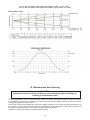
Table of tilt angles for dierent loads of the stacker
Hole position 1 2 3 4 5 6 7 8 9
2 xtures -22 -10° 0° 10° 20° 30° 37° 45° -
4 xtures -10° -5° 0° 8° 15° 20° 25° 30° 35°
6 xtures -7.5° -3° 0° 5° 10° 15° 20° 22° 26°
.

10
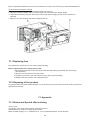
To install multiple xtures in a top-to-bottom method
1. Rig the stacker to the truss (4) by means of two omega holders (2) on the U-holder (5) and two clamps (1)
and secure it with two safety wires (15). Use only safety wires with snap hook with screw lock gate.
The snap hooks have to go throw holes in the stacker.
2. Check if the locking mechanism of the rst xture is in an "unlock position" - the lever (18) is in the bottom
position and the red mark (16) is visible.
3. Connect the rst xture with the stacker in a way that feet (8) of the stacker will be
inserted into top openings (14) of the rst xture and move the rst xture in a direction as show
red arrows on the picture below until you feel a stop.
4. Secure the rst xture with the stacker by means of its locking mechanism: move both levers (18)
to the top position until the green mark (17) is visible and move the plastic levers (19) into position under
locking levers (18) until they snap. Now levers (18) cannot be moved to unlock position.
5. Make the secondary securing of the installed xture. Loosen both tilt locks (9) and move the U-holder (13)
to the horizontal position. Loosen the nuts (12) and move the segments (11) towards the stacker nuts (7).
Loosen the nuts (7) and fasten the segments (11) under them. Tighten the nuts (7) and the tilt locks (9).
Always check that locking mechanisms are locked before connecting next xture!
6. Check if the locking mechanism of the second xture is in the "unlock position" - the lever (18) is in
the bottom position and the red mark (16) is visible.
7. Connect the second xture with the rst one in a way that feet (8) of the rst xture will be
inserted into top openings (14) of the second xture and move the second xture in a direction as show
red arrows on the picture above until you feel a stop.
8. Secure the second xture with the rst one by means of its locking mechanism: move both levers (18)
to the top position until the green mark (17) is visible and move the plastic levers (19) into position under
locking levers (18) until they snap. Now levers (18) cannot be moved to unlock position.
9. Make the secondary securing of this xture. Loosen both tilt locks (9) and move the U-holder (13)
to the horizontal position. Loosen the nuts (12) and move the segments (11) towards the nuts (10).
Loosen the nuts (10) and fasten the parts (11) under them. Tighten the nuts (10) and the tilt locks (9).
10. Repeat steps 6-9 for the next xture. In this way, up to six xtures can be connected each other.
11. Check, that all nuts (7), (10) and tilt locks (9) are fully tightened.

11
Always keep correct orientation of xtures towards the stacker.
Warning for outdoor operation!
To ensure declared IP rating, the xture must be in the following positions only (towards ground).
Allowed tilt must not be higher than +/-15° from a horizontal axis of the xture.
The display covering transparent cover must be closed and its four screws fully tightened.
Fixture´s XLR connectors are dust and water protected according to IP 65 by mating with related X-HD cable
connectors.
They cannot stay disconnected outdoor. DMX output connector (XLR female) at the last fixture in a DMX line
has to be covered with the rubber cap before inserting a terminator. The rubber cap does not supply the termi-
nator. The XLR terminator (male) has to be dust and water protected.
If the fixture is to be outdoor without connecting to DMX line, always interconnect its DMX input with DMX output
to keep declared IP rating of XLR connectors.
Ethernet connection is not suitable for outdoor environment, especially in rain!

12
Multiply xtures installation via oor stand
Maximum 6 xtures can be connected in the top-to-bottom method
Always use a oor stand for multiply xture installation in the top-to-bottom method on the oor.
To install multiple xtures in the top-to-bottom method on the oor stand
1. Move both levers (23) to unlock position (red mark is visible) on the oor stand (21).
2. Put the rst xture with its feet (8) into the slots (22) in the oor stand (21) and move the xture in
a direction as show red arrows on the picture below until you feel a stop.
3. Secure the xture in the oor stand by means of its locking mechanism: move both levers (23)
to the position until the green mark is fully visible.
4. Put the second xture with its feet (8) into the slots (14) in the rst xture and move the xture in
a direction as show red arrows on the picture below until you feel a stop.
5. Secure the rst xture with the second one by means of its locking mechanism: move both levers (18)
to the top position until the green mark (17) is visible and move the plastic levers (19) into position under
locking levers (18) until they snap. Now levers (18) cannot be moved to unlock position.
6. Make the secondary securing of this xture. Loosen both tilt locks (9) and move the U-holder (13)
to the horizontal position. Loosen the nuts (12) and move the segments (11) towards the nuts (10).
Loosen the nuts (10) and fasten the parts (11) under them. Tighten the nuts (10) and the tilt locks (9).
7. Repeat steps 4-6 for next xture. In this way, up to six xtures can be connected each other.
8. Check, that all nuts (10) and tilt locks (9) are fully tightened.
Always check that locking mechanisms are locked before connecting next xture!
.

13
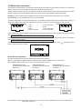
3.4 DMX-512 connection
The xture is equipped with 5-pin XLR sockets for DMX input and output.The sockets are wired in parallel.
Only use a shielded twisted-pair cable designed for RS-485 and 5-pin XLR-plugs and connectors in order to
connect the controller with the xture or one xture with another.
DMX - output DMX-input
If you are using the standard DMX controllers, you can connect the DMX output of the controller directly with
the DMX input of the rst xture in the DMX-chain. If you wish to connect DMX controllers with other
XLR-outputs, you need to use adapter cables.
Building a serial DMX-chain:
Connect the DMX output of the rst xture in the DMX-chain with the DMX input of the next xture. Always connect
one output with the input of the next xture until all xtures are connected. Up to 32 xtures can be connected.
Caution: At the last xture, the DMX cable should be terminated with a terminator. Solder a 120 Ω resistor
between Signal (–) and Signal (+) into a 5-pin XLR-plug and plug it in the DMX output of the last xture.
1 - Shield
2 - Signal (-)
3 - Signal (+)
4 - Used for wireless DMX
5 - Used for wireless DMX
1 - Shield
2 - Signal (-)
3 - Signal (+)
4 - Used for wireless DMX
5 - Used for wireless DMX

14
3.5 Ethernet connection
The xtures on a data link are connected to the Ethernet with ArtNet communication protocol.The control soft-
ware running on your PC (or light console) has to support Art-Net protocol.
Art-Net communication protocol is a 10 Base T Ethernet protocol based on the TCP/IP.Its purpose is to allow
transfer of large amounts of DMX 512 data over a wide area using standard network technology.
IP address is the Internet protocol address.The IP uniquely identies any node (xture) on a network.
The Universe is a single DMX 512 frame of 512 channels.
The Robin 300E Wash is equipped with 8-pin RJ- 45 socket for Ethernet input.Use a network cable category 5
(with four “twisted” wire pairs) and standard RJ-45 plugs in order to connect the xture to the network.
RJ-45 socket (front view): RJ-45 plug (front view):
1- TD+ 5- Not connected
2- TD- 6- RX-
3- RX+ 7- Not connected
4- Not connected 8- Not connected
Patch cables that connect xtures to the hubs or LAN sockets are wired 1:1,that is,pins with the same numbers
are connected together:
1-1 2-2 3-3 4-4 5-5 6-6 7-7 8-8
If only the xture and the computer are to be interconnected,no hubs or other active components are needed.A
cross-cable has to be used:
1-3 2-6 3-1 4-8 5-7 6-2 7-5 8-4
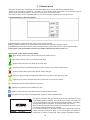
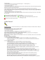
If the xture is connected with active Ethernet socket (e.g. switch) the network icon will appear at the
bottom right corner of the screen:
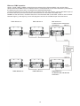
Direct Ethernet operation
Connect the Ethernet inputs of all xtures with the Ethernet network.
Option “ Artnet (gMaI or gMA2)" has to be selected from “Ethernet Mode” menu on the xture.
Set IP address (002.xxx.xxx.xxx / 010.xxx.xxx.xxx) and the Universe.
(DMX address=186) (DMX address=38) (DMX address=1)
IP addres=002.168.002.004 IP addres=002.168.002.003 IP addres=002.168.002.002
Universe=1 Universe=1 Universe=1
An advised PC setting: IP address: 002.xxx.xxx.xxx / 010.xxx.xxx.xxx (Dierent from xture IP addresses)
NET mask: 255.0.0.0

15
Ethernet / DMX operation
Option “ Artnet" (gMaI or gMA2 or sACN) has to be selected from “Ethernet Mode” menu at rst xture.
Option “Ethernet To DMX” has to be selected from the “Ethernet Mode” menu at the rst xture (connected to
the Ethernet) in the xture chain, next xtures have standard DMX setting.
Connect the Ethernet-input of the rst xture in the data chain with the network. Connect the DMX output of
this xture with the input of the next xture until all xtures are connected to the DMX chain.
Caution: At the last xture, the DMX chain has to be terminated with a terminator. Solder a 120 Ω resistor
between Signal (–) and Signal (+) into a XLR-plug and connect it in the DMX-output of the last xture.
DMX address=41 DMX address=9 DMX address=1
IP address=002.168.002.002
Universe=0
DMX address=41 DMX address=9 DMX address=1
IP address=002.168.002.003
Universe=1

16
4. Control menu map
Default settings=Bold print
Tab Level 1 Level 2 Level 3 Level 4 Level 5 Level 6
Addressing Settings DMX Address 001-512
DMX Presets Mode 1
:
Mode 4
Ethernet Settings Ethernet Mode Disable
ArtNet
gMAI
gMA2
sACN
Ethernet To DMX On
O
IP Address/NetMask Default IP Address
Custom IP Address
Net Mask
ArtNet Universe 0-255
MANet settings MANet I/IIUniverse 1-256
MANet Session ID 1-32
sACN Settings sACN Universe
sACN Priority
Information Fixture Times Power On Time Total Hours
Resetable Hours
Fixture Temperatures
LEDs Temperature Current
Maximum NonRes.
Maximum Res.
Leds Board tempe-
rature
Current
Maximum NonRes.
Maximum Res.
Base Temperature Current
Maximum NonRes.
Maximum Res.
DMX Values Int. All Zones
:
Zone 12 Intensity
Wireless State Signal Quality
Unlink Wireless Adapter
Power Channel
State
Software Versions Display System
Module L
Product IDs Mac Address
RDM UID
RDM Label
View Logs Fixture Errors
Fixture Status Power On
Power O
Fixture Position
Fixture Temperatures LEDs Temperature
Base Temperature
Personality User Mode User A Settings
User B Settings
User C Settings

17
Tab Level 1 Level 2 Level 3 Level 4 Level 5 Level 6
DMX Presets Mode 1
:
Mode 4
View Selected Preset
DMX Input Wired Input
Wireless Input
Wireless In/XLR Out
DMX Hold O, On
Microphone Sen-
sitivity
1-10-20
Douse Settings O, On
Dimmer Curve Linear
Square Law
Init Eect Positions Int. All Zones 0-255
:
Zone 12 Intensity 0-255
Screen Settings Display Intensity 1-10
Screen Saver Delay O-10min.
Touchscreen Lock O-10min.
Recalibrate Touch-
screen
Display Orientation Normal
Inverted
Auto
Temperature Unit °C,°F
Fan Mode Auto, high
Date & Time Settings
Default Settings
Manual Control Manual Eect Con-
trol
Int. All Zones 0-255
:
Zone 12 Intensity 0-255
Stand -Alone Test Sequences
MusicTrigger O, On
Preset Playback None
Test
:
Prog. 3
Play Program Play Program 1
Play Program 2
Play Program 3
Edit Program Edit Program 1 Start Step 1-100
End Step 1-100
Edit Program Steps Step 1 Int. All Zones 0-255
: :
: Step Time 0-25.5s
: Fade Time 0-25,5s
Step 100 Int. All Zones 0-255
:
Step Time 0-25.5s
Fade Time 0-25,5s
Service Update Software

18
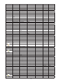
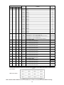
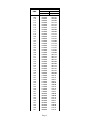
DMX protocol
Version: 1.2
1234
1111
Intensity (8bit)-all zones
0-5 Closed (mode 3,4 only)
step
6-255 Coarse intensity from min. to max. (Mode 3,4 only)
proportional
0-255 Coarse intensity from min. to max. (Mode 1,2 only)
proportional
22**
Intensity (16bit)-all zones
0-255 Fine intensity from min. to max.
proportional
3322
Duration
0-255 Light time duration from min. —>max.
step
4433
Rate
0-5 No flash
step
6-255 Flash frequency from min. —>max
step
Note: Duration time<Rate: flashing
Duration time>= Rate: Light continuously On
55*4
Special effects
0-5 No function (Mode 3,4 only)
step
0-1 No function (Mode 1,2 only)
step
2-5 Permanent lightening (Mode 1,2 only)
step
6-42
Ramp up
(use channels Duration and Rate for control)
step
43-85
Ramp down
(use channels Duration and Rate for control)
step
86-128
Ramp up/down
(use channels Duration and Rate for control)
step
129-171
Random strobe
(use channel Rate for control)
step
172-214
Lightning
(use channel Rate for control)
step
215-255
Spikes
(use channels Duration and Rate for control)
step
66**
Special Functions
0 -19 Reserved
To activate following functions , stop in DMX value for at least 3
sec. Corresponding menu items are temporarily overrided.
20-24
Graphic display On
step
25-29
Graphic display Off
step
30-59
Reserved
60-64
Fans mode: Auto
step
65-69
Fans mode: high
step
70-79
Douse On*
step
80-89
Douse Off*
step
90-99
Dimmer curve: linear
step
100-109
Dimmer curve: square law
step
110-255
Reserved
77**
Zone Effects
0-2
No function
step
3-4 Effect 1
step
5-6 Effect 2
step
7-8 Effect 3
step
9-10 Effect 4
step
11-12 Effect 5
step
Robin Strobe - DMX protocol
Mode 1 – Zone effects mode , Mode 2 –Zone mode , Mode 3 –Three channel mode , Mode 4 – Four channel mode
Mode/channel
DMX
value
Function
Type of
control
Page 1
5. DMX chart

19
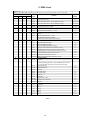
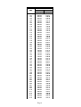
DMX protocol
1234
Mode/channel
DMX
value
Function
Type of
control
13-14 Effect 6
step
15-16 Effect 7
step
17-18 Effect 8
step
19-20 Effect 9
step
21-22 Effect 10
step
23-24 Effect 11
step
25-26 Effect 12
step
27-28 Effect 13
step
29-30 Effect 14
step
31-32 Effect 15
step
33-34 Effect 16
step
35-36 Effect 17
step
37-38 Effect 18
step
39-40 Effect 19
step
41-42 Effect 20
step
43-44 Effect 21
step
45-46 Effect 22
step
47-48 Effect 23
step
49-50 Effect 24
step
51-52 Effect 25
step
53-255 Reserved
step
8 8 * * Zone Effects Speed
0-63 Speed from min. —>max. without fade time
proportional
64-127 Speed from max. —>min. without fade time (op. direction)
proportional
128-191 Speed from min. —>max. with fade time
proportional
192-255 Speed from max. —>min. with fade time (op. direction)
proportional
* 9 * * Zone 1-intensity (8bit)
0-255 Coarse intensity from 0% to 100%
proportional
* 10 * * Zone 2-intensity (8bit)
0-255 Coarse intensity from 0% to 100%
proportional
* 11 * * Zone 3-intensity (8bit)
0-255 Coarse intensity from 0% to 100%
proportional
* 12 * * Zone 4-intensity (8bit)
0-255 Coarse intensity from 0% to 100%
proportional
* 13 * * Zone 5-intensity (8bit)
0-255 Coarse intensity from 0% to 100%
proportional
* 14 * * Zone 6-intensity (8bit)
0-255 Coarse intensity from 0% to 100%
proportional
* 15 * * Zone 7-intensity (8bit)
0-255 Coarse intensity from 0% to 100%
proportional
* 16 * * Zone 8-intensity (8bit)
0-255 Coarse intensity from 0% to 100%
proportional
* 17 * * Zone 9-intensity (8bit)
0-255 Coarse intensity from 0% to 100%
proportional
* 18 * * Zone 10-intensity (8bit)
0-255 Coarse intensity from 0% to 100%
proportional
* 19 * * Zone 11-intensity (8bit)
0-255 Coarse intensity from 0% to 100%
proportional
* 20 * * Zone 12-intensity (8bit)
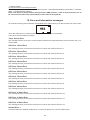
Page 2
LED zones order
Note. Set the same dimmer curve on all xtures in order to ensure the same eect running.
* The function does not influence channels Special Effects, Zone Effects and Zone 1 Intensity- Zone
12 Intensity

20
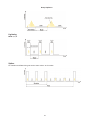
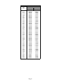
6. Strobe and Special eects running
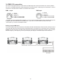
6.1 Strobe
Mode 3 and 4
Mode 1 and 2
6.2 Special eects
Rumping
Rump Up
Rump Down
Page is loading ...
Page is loading ...
Page is loading ...
Page is loading ...
Page is loading ...
Page is loading ...
Page is loading ...
Page is loading ...
Page is loading ...
Page is loading ...
Page is loading ...
Page is loading ...
Page is loading ...
Page is loading ...
Page is loading ...
Page is loading ...
Page is loading ...
Page is loading ...
Page is loading ...
Page is loading ...
Page is loading ...
Page is loading ...
Page is loading ...
Page is loading ...
Page is loading ...
Page is loading ...
Page is loading ...
Page is loading ...
Page is loading ...
Page is loading ...
Page is loading ...
Page is loading ...
Page is loading ...
Page is loading ...
Page is loading ...
Page is loading ...
Page is loading ...
Page is loading ...
-
 1
1
-
 2
2
-
 3
3
-
 4
4
-
 5
5
-
 6
6
-
 7
7
-
 8
8
-
 9
9
-
 10
10
-
 11
11
-
 12
12
-
 13
13
-
 14
14
-
 15
15
-
 16
16
-
 17
17
-
 18
18
-
 19
19
-
 20
20
-
 21
21
-
 22
22
-
 23
23
-
 24
24
-
 25
25
-
 26
26
-
 27
27
-
 28
28
-
 29
29
-
 30
30
-
 31
31
-
 32
32
-
 33
33
-
 34
34
-
 35
35
-
 36
36
-
 37
37
-
 38
38
-
 39
39
-
 40
40
-
 41
41
-
 42
42
-
 43
43
-
 44
44
-
 45
45
-
 46
46
-
 47
47
-
 48
48
-
 49
49
-
 50
50
-
 51
51
-
 52
52
-
 53
53
-
 54
54
-
 55
55
-
 56
56
-
 57
57
-
 58
58


Robe Robin Strobe User manual
- Category
- Stroboscopes & disco lights
- Type
- User manual
Ask a question and I''ll find the answer in the document
Finding information in a document is now easier with AI
Related papers
-
Robe Robin StLight User manual
-
-
-
-
-
-
-
-
-
Other documents
-
Robin DLS User manual
-
-
 Robert Juliat SULLY 305L User manual
-
High End Systems SolaFrame 750 User manual
-
High End Systems High End Systems SolaWash 1000 User manual
-
-
 JB-Lighting Sparx 18 User manual
-
 Eurex 738500 Datasheet
-
 JB-Lighting P9 Spot User manual
-
 JB-Lighting P12 Wash User manual


