
No: 341102 – 01/15
Pass & Seymour
®
Harmony
®
Multilocation Dimmer; Ratings: Incandescent: 700W; CFL, LED: 450W; MLV 700VA
Harmony
®
Variateur à multilocalisation ; Puissance nominale : à incandescence ; 700 W ;
lampe uo-compacte, DEL : 450 W ; transformateur 700 VA
Regulador de ubicación múltiple Harmony
®
; especicaciones: Incandescente: 700 W; CFL, LED: 450 W; MLV 700 VA
Installation Instructions • Notice d’Installation • Instrucciones de Instalación
Catalog Number(s) • Numéro(s) de catalogue • Número(s) de catálogo: HCL453PMM and HMR
Country of Origin: Made in China • Pays d’origine : Fabriqué en Chine • País de origen: Hecho en China
IMPORTANT NOTES:
1. All dimmers can be damaged by improper wiring. Check for short circuits
prior to installing the dimmer with a lamp load in the circuit.
Procedure for short circuit check:
a. Disconnect power to circuit by removing fuse or turn circuit breakers
OFF.
b. Install a switch instead of the dimmer. Turn the switch to the ON position.
c. Turn power ON. If the circuit breaker trips, a short circuit is present.
If the light fails to turn ON and OFF with the switch, the wiring may
be incorrect.
d. Correct wiring, if necessary, and retest.
e. Install the dimmer only after the light operates properly with the switch.
2. Protect this product from dust and dirt. The dimmer can be damaged by
contaminates encountered during the construction process. If lighting
is required prior to the construction process completion, then a switch
should be temporarily installed in place of this product. This product
should not be installed until the construction process is complete.
Any dimmer damage due to improper installation is not covered
under warranty.
DIRECTIONS
Figure 1 / Figure 1 / Figura 1
1. If color change kit was provided, and a different color is desired, see the
Color Change Procedure, (Figure 1), if not proceed to step #2.
2. Disconnect power to the circuit by removing the fuse or turning the circuit
breaker to the off position.
3. Remove wall plate and switch mounting screws, pull existing switch from
wall box.
4. Disconnect existing switch from circuit. For existing 3-way installations:
identify the “Common” wire (wire connected to the terminal marked
common, this terminal may also be of a different color). For new
installation identify wire connected to power source or load.
5. Connect dimmer as shown in the applicable installation diagram using
#12 or #14 AWG wire stranded or solid copper conductors. Note that
the dimmer and remote positions may not be reversed from that shown.
Strip the wire to the length shown on the back of the product.
6. Install product in wall box, with the word “Top” on the strap right side up,
using mounting screws provided.
7. Attach wall plate and then restore power to the unit.
8. The dimmer may require adjustment to the low end setting to reliably
start and/or remove flickering in bulbs. Make adjustment as stated in
the “User Adjustable Parameters” section of the DIMMER OPERATION
section.
NOTE: It is normal for the dimmer to feel warm during operation. Use a
separate neutral wire for each phase of a multiphase system containing
a dimmer, and for high power single phase applications where flickering
is present.
Any combination of dimmer models and other devices may be ganged
together. De-rate the maximum load according to the following table:
Rated Load 3 Gang (or more) Installation
Incd./Hal. 700W 650W
MLV 700VA 650VA
CLF/LED 450W 450W
Single-Pole Installation
1. NOTE: Wire colors indicated are those of the device only, not the wires
in the wall box. Be sure to test wall box wires before making any
connections.
2. Connect the device following the single-pole wiring diagram shown.
Three-Way Installation
1. NOTE: Three-way or multi-location applications require the use of a Multi-
Location Remote HMR, in conjunction with a Preset Dimmer. A regular
three-way switch should not be used to control a Multi-Location Dimmer.
Doing so may damage the control and, in turn, void the unit’s warranty.
See Wiring Diagram Figures 2-5 below.
OPERATION
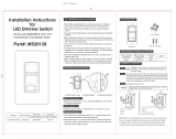
User Interface – Overview
The user interface of the dimmer consists of:
[1] Locator LED
[2] ON/OFF Pushbutton
[3] Seven-Element LED Bar Graph
[4] Air Gap Switch
[5] RAISE/LOWER Rocker buttons
LED Indicators
Load Off – When the dimmer is powered, but
the load is OFF, the locator LED [1] will be on at the full intensity
(if enabled), and all LEDs in the bar graph [3] will be off.
Load On – When the dimmer is operating the load (load ON), the locator
LED [1] will be off, and the bar graph [3] will be illuminated starting from
the bottom, to indicate the present load brightness level.
Setup Modes – The function of the LEDs varies with each specific setup
mode, and will be detailed in those descriptions.
ON/OFF Pushbutton [2]
• Momentary push of ON/OFF button with Load OFF fades load on to LDL
(last dim level) at 50%/second.
• Momentary push of ON/OFF button with Load ON fades load off at a
rate of 50%/second (from full on, it will take 2 sec to off).
• Push and hold of ON/OFF button for approximately 2s with load ON
fades load off over approximately 30s (“go to bed” feature). During the
slow fade-off interval the top-most lit LED in the bar graph will flash at
approximately 3Hz (3 times per second).
• Double-tap of ON/OFF button with Load ON fades load to maximum
brightness at 50%/second.
RAISE Rocker button (+) [5]
• Momentary push with Load ON increases brightness 1 increment
(approx. 7% of max brightness).
• Push and hold for more than 0.5 seconds with Load ON ramps
brightness up at 20%/second (approx 5 sec from min to max).
LOWER Rocker button (-) [5]
• Momentary push with Load ON decreases brightness 1 increment
(approx 7% of max brightness).
• Push and hold for more than 0.5 seconds with load ON ramps brightness
down at 20%/second (approx 5 sec from max to min).
Air gap switch [4]
• Slide to OFF position before replacing load. Slide to ON position after
load has been replaced.
USER-ADJUSTABLE PARAMETERS
Min Level Trim
• Hold LOWER Rocker button (-) [5] down for approximately 10s after
minimum brightness reached. Bar graph LEDs will flash to indicate
calibration mode activated.
• Pressing ON/OFF pushbutton [2] cycles through 12 preset trim levels,
which are displayed on the bar graph.
• Pressing either the Raise or Lower rocker button [5] exits calibration and
stores selected trim level.
The default value for the min level trim is set to a level adequate for stable
operation of a typical LED load.
Max Level Trim (energy saver)
• Hold RAISE Rocker button (+) [5] down for approximately 10s after
maximum brightness reached. Bar graph LEDs will flash to indicate cal
mode activated.
• Pressing ON/OFF pushbutton [2] cycles through 12 preset trim levels,
which are displayed on the bar graph.
• Pressing either Raise or Lower rocker pushbuttons exits calibration and
stores selected trim level.
The default value for the max level trim is 100%.
Disable/Enable Locator LED [1]
Holding the ON/OFF pushbutton [2] down for approximately 10s with load
OFF, until Locator LED flashes once in confirmation, disables operation
of the Locator LED when load is off. Continuing to hold the button for an
additional 2s (12s total), until the Locator LED flashes twice in confirmation,
enables the Locator LED operation.
Factory Reset
With the unit in the OFF state, hold down the ON/OFF pushbutton [2] for
15 seconds. The bar graph and locator LEDs will flash 3 times to indicate
that the minimum and maximum trim levels and locator LED parameters
have been reset to defaults.
Power Failure Recovery
In the case of a power failure, the dimmer saves its last operating state to
memory. When power is restored, if the dimmer load was on, the dimmer
will automatically fade, at 20%/second rate, to the level at the time of the
power failure.
DIMMER / VARIATEUR / REGULADOR
REMOTE / TÉLÉCOMMANDE /
DISPOSITIVO REMOTO
REMOTE / TÉLÉCOMMANDE /
DISPOSITIVO REMOTO
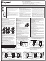
Line (Hot/Black) Wire
Noir – Câble secteur/Sous tension
Cable de línea (vivo/negro)
120VAC
60Hz
120 VCA,
60 Hz
120 V CA,
60 Hz
Load
Charge
Carga
Neutral (White) Wire / Fil neutre (blanc) / Cable neutro (blanco)
Green Wire
Fil vert
Cable verde
Terminal Labeled Remote Red Screw
Borne marquée télécommandée – Vis rouge
Terminal etiquetada
para el dispositivo
remoto; tornillo rojo
Terminal Labeled Remote Red Screw
Borne marquée télécommandée – Vis rouge
Terminal etiquetada
para el dispositivo
remoto; tornillo rojo
Terminal Labeled
Remote Red Screw
Borne marquée
télécommandée –
Vis rouge
Terminal etiquetada
para el dispositivo
remoto; tornillo rojo
Ground
Tierre
Tierra
Ground
Tierre / Tierra
Traveler Wire #2
Fil mobile n° 2
Cable puente n.º 2
Traveler Wire #1 / Fil mobile n° 1 / Cable puente n.º 1
Terminal Labeled
Load Brass Screw
Borne marquée
charge – Vis en laiton
Terminal etiquetada
para la carga;
tornillo de latón
Terminal Labeled
Load Brass Screw
Borne marquée charge –
Vis en laiton
Terminal etiquetada para
la carga; tornillo de latón
Terminal Labeled
Load Brass Screw
Borne marquée charge –
Vis en laiton
Terminal etiquetada para
la carga; tornillo de latón
Green Wire
Fil vert
Cable verde
Green Wire
Fil vert
Cable verde
Terminal Labeled
Hot, Black Screw
Borne marquée chaude –
Vis noire
Terminal etiquetada
para el conductor
vivo; tornillo negro
!
* *
Line (Hot/Black) Wire
Noir – Câble secteur/Sous tension
Cable de línea (vivo/negro)
120VAC
60Hz
120 VCA,
60 Hz
120 V CA,
60 Hz
Load
Charge
Carga
Neutral (White) Wire / Fil neutre (blanc) / Cable neutro (blanco)
Green Wire
Fil vert
Cable verde
Terminal Labeled
Remote Red Screw
Borne marquée
télécommandée –
Vis rouge
Terminal etiquetada
para el dispositivo
remoto; tornillo rojo
Terminal Labeled Remote Red Screw
Borne marquée télécommandée – Vis rouge
Terminal etiquetada
para el dispositivo
remoto; tornillo rojo
Terminal Labeled
Remote Red Screw
Borne marquée
télécommandée –
Vis rouge
Terminal etiquetada
para el dispositivo
remoto; tornillo rojo
Ground
Tierre
Tierra
Ground
Tierre
Tierra
Ground
Tierre / Tierra
Terminal Labeled
Load Brass Screw
Borne marquée charge –
Vis en laiton
Terminal etiquetada para
la carga; tornillo de latón
Terminal Labeled
Load Brass Screw
Borne marquée charge –
Vis en laiton
Terminal etiquetada para
la carga; tornillo de latón
Green Wire
Fil vert
Cable verde
Green Wire
Fil vert
Cable verde
Terminal Labeled
Hot, Black Screw
Borne marquée
chaude – Vis noire
Terminal etiquetada
para el conductor
vivo; tornillo negro
*Either load terminal can be used / *N’importe quelle borne de charge peut être utilisée / *Se puede usar cualquier terminal de carga.
DIMMER / VARIATEUR / REGULADOR
REMOTE / TÉLÉCOMMANDE /
DISPOSITIVO REMOTO
REMOTE / TÉLÉCOMMANDE /
DISPOSITIVO REMOTO
HCL453PMM
READ AND SAVE THESE INSTRUCTIONS
To be installed by a certified electrician or other qualified person.
WARNING: To prevent severe shock or electrocution, always turn power off at the
service panel before installing this product, working on the circuit or changing a lamp.
CAUTION
• To reduce the risk of overheating and possible damage to this product or other
equipment do not use this product to control a receptacle, a motor operated
appliance or a transformer based appliance.
• Do not use this product with loads whose power requirements exceed the maximum
power (stated in watts, amperes or volt-amperes) of the dimmer.
• Use only with incandescent, compatible dimmable CFL/LED bulbs which screw into
conventional incandescent lamp sockets, or MLV loads (compatible bulbs listed at
www.legrand.us).
• A 5 watt minimum load is required.
• Do not connect this product to a power source other than 120VAC, 60Hz.
• Use copper wire only.
• Always slide the Air Gap Switch to the full down (OFF) position when changing a light
bulb.
• For MLV loads:
- The maximum VA rating of this dimmer applies to the transformer input of the MLV,
not the load connected to the transformer secondary of the MLV.
- Do not use to control a solid state electronic low voltage transformer.
- Do not use with inoperative or missing lamps. Use of this dimmer with inoperative
or missing lamps can create an over current condition which may damage the
transformer. Use transformers that incorporate thermal protection or a fuse at the
primary windings.
LISEZ ET CONSERVEZ CES INSTRUCTIONS
Ce dispositif doit être installé par un électricien certifié ou une autre personne qualifiée.
AVERTISSEMENT : afin d’éviter tout choc électrique ou électrocution grave, toujours
éteindre l’alimentation sur le panneau de service avant d’installer ce produit, de
travailler sur le circuit ou de changer une lampe.
MISE EN GARDE :
• Pour réduire le risque de surchauffe et d’autres dommages possibles sur ce produit
ou d’autres appareils, ne pas utiliser ce produit pour contrôler une prise électrique,
un appareil à moteur ou un appareil avec transformateur.
• Ne pas utiliser ce produit avec des ampoules dont les besoins en énergie dépassent
la puissance maximale (exprimée en watts, en ampères ou en voltampères) du
variateur.
• Utiliser uniquement ce produit avec des ampoules compatibles, à incandescence,
fluo-compactes/DEL, à intensité réglable, pouvant être vissées dans des douilles
conventionnelles pour ampoules à incandescence, ou des charges de transformateur
(ampoules compatibles répertoriées sur le site www.legrand.us).
• Une ampoule d’au moins 5 watts est requise.
• Ne brancher ce produit qu’à une source d’alimentation de 120 V c.a., 60 Hz.
• N’utilisez que des fils en cuivre.
• Au moment de changer l’ampoule, faire glisser l’interrupteur Air Gap jusque dans sa
position la plus basse (OFF).
• Pour les charges de transformateur :
- La capacité maximale en VA de ce dispositif s’applique à l’entrée du transformateur
et non pas à la charge au niveau de la partie secondaire du transformateur.
- Ne pas s’en servir pour commander un transformateur électronique basse tension
à semi-conducteurs.
- N’utilisez pas ce dispositif avec des lampes défaillantes ou manquantes.
L’utilisation de cette unité avec des lampes défaillantes ou manquantes peut créer
une situation de surintensité qui risque d’endommager le transformateur. Utilisez
des transformateurs équipés d’une protection thermique ou d’un fusible au niveau
des enroulements primaires.
LEA Y GUARDE ESTAS INSTRUCCIONES
La instalación debe estar a cargo de un electricista certificado u otra persona
calificada.
ADVERTENCIA: Para evitar una fuerte descarga eléctrica o la electrocución, siempre
desconecte el suministro eléctrico en el panel de servicio antes de instalar este
producto, trabajar en el circuito o cambiar una lámpara.
PRECAUCIÓN
• Para reducir el riesgo de sobrecalentamiento y posibles daños a este producto u
otros equipos, no use este producto para controlar un receptáculo, un dispositivo
accionado por motor o un dispositivo con transformador.
• No use este producto con cargas cuyos requisitos de potencia superen la potencia
máxima (expresada en vatios, amperios o voltio-amperios) del regulador.
• Úselo solo con bombillas CFL/LED incandescentes regulables compatibles que se
inserten en casquillos para lámparas incandescentes convencionales o con cargas
MLV (bombillas compatibles detalladas en www.legrand.us).
• Se requiere una carga mínima de 5 W.
• No conecte este producto a una fuente de alimentación que no sea de 120 V AC,
60 Hz.
• Use solamente cables de cobre.
• Siempre deslice el interruptor de espacio de aire a la posición totalmente hacia abajo
(apagado) al cargar una bombilla.
• Para las cargas MLV:
- La capacidad nominal máxima de VA de este regulador corresponde a la entrada
del transformador de MLV, no a la carga conectada al transformador secundario
del MLV.
- No lo use para controlar un transformador de bajo voltaje electrónico de estado
sólido.
- No lo use con lámparas defectuosas o faltantes. El uso del regulador con lámparas
defectuosas o faltantes puede crear una condición de corriente en exceso que
puede dañar el transformador. Use los transformadores que tienen protección
térmica o un fusible en los arrollamientos primarios.
HMR
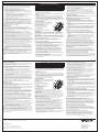
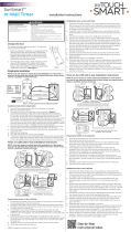
Two or More Location Control (Up to 9 Remotes) Wiring Option B: Connecting Remote To Neutral
Contrôle de localisation double ou davantage (jusqu’à 9 télécommandes) Option de câblage B :
Raccordement de la télécommande au neutre
Opción de cableado B para control de dos o más ubicaciones (hasta 9 dispositivos remotos):
Conexión de dispositivo remoto a neutro
1. 2. 3.
4. 5. 6.
Ground
Tierre
Tierra
Terminal Labeled
Remote. Red Screw
Is Not Used.
Borne marquée
télécommandée.
La vis rouge n’est
pas utilisée.
Terminal etiquetada
para el dispositivo
remoto. El tornillo
rojo no se usa.
120VAC
60Hz
120 VCA,
60 Hz
120 V CA,
60 Hz
Load
Charge
Carga
Terminal Labeled Hot - Black Screw
Borne marquée chaude - Vis noire
Terminal etiquetada para el conductor
vivo; tornillo negro
Neutral (White) Wire
Fil neutre (blanc)
Cable neutro (blanco)
Line (Hot/Black) Wire
Borne marquée chaude - Vis noire
Cable de línea (vivo/negro)
Terminal
Labeled Load
Brass Screw
Borne marquée
charge - Vis
en laiton
Terminal
etiquetada
para la carga;
tornillo de latón
Green Wire
Fil vert
Cable verde
DIMMER / VARIATEUR / REGULADOR
Figure 2 / Figure 2 / Figura 2
Terminal Labeled Remote Red Screw
Borne marquée télécommandée – Vis rouge
Terminal etiquetada para el
dispositivo remoto; tornillo rojo
Line (Hot/Black) Wire
Noir – Câble secteur/Sous tension
Cable de línea (vivo/negro)
REMOTE / TÉLÉCOMMANDE /
DISPOSITIVO REMOTO
DIMMER / VARIATEUR / REGULADOR
Terminal Labeled
Remote Red Screw
Borne marquée
télécommandée –
Vis rouge
Terminal etiquetada
para el dispositivo
remoto; tornillo rojo
120VAC
60Hz
120 VCA,
60 Hz
120 V CA,
60 Hz
Ground
Tierre
Tierra
Ground
Tierre / Tierra
Load
Charge
Carga
Traveler Wire #2
Fil mobile n° 2
Cable puente n.º 2
Traveler Wire #1 / Fil mobile n° 1 / Cable puente n.º 1
Neutral (White) Wire / Fil neutre (blanc) / Cable neutro (blanco)
Terminal Labeled
Load Brass Screw
Borne marquée
charge – Vis en laiton
Terminal etiquetada
para la carga;
tornillo de latón
Terminal Labeled
Load Brass Screw
Borne marquée charge –
Vis en laiton
Terminal etiquetada para
la carga; tornillo de latón
Green Wire
Fil vert
Cable verde
Green Wire
Fil vert
Cable verde
Terminal Labeled
Hot, Black Screw
Borne marquée
chaude – Vis noire
Terminal etiquetada
para el conductor
vivo; tornillo negro
Figure 3 / Figure 3 / Figura 3
WIRING DIAGRAMS / SCHÉMAS DE CÂBLAGE / DIAGRAMAS DE CABLEADO
Single Location Control (Using Existing Single Pole Switch Wiring)
Contrôle de localisation unique (à l’aide du câblage de commutation
unipolaire existant)
Control de una sola ubicación (con el cableado del interruptor unipolar existente)
Two Location Control (Using Existing 3-Way Switch Wiring)
Contrôle de localisation double (à l’aide du câblage de commutation à trois voies existant)
Control de dos ubicaciones (con el cableado del interruptor de 3 vías existente)
Figure 4 / Figure 4 / Figura 4 Figure 5 / Figure 5 / Figura 5
Two or More Location Control (Up to 9 Remotes) Wiring Option A: Connecting Load Through Remotes
Contrôle de localisation double ou davantage (jusqu’à 9 télécommandes) Option de câblage A :
Raccordement d’une charge par le biais de télécommandes
Opción de cableado A para control de dos o más ubicaciones (hasta 9 dispositivos remotos) A:
Conexión de la carga a través de dispositivos remotos
Page is loading ...
-
 1
1
-
 2
2


Radiant radiant Multi-Location Dimmers Installation guide
- Type
- Installation guide
- This manual is also suitable for
Ask a question and I''ll find the answer in the document
Finding information in a document is now easier with AI
in other languages
Related papers
-
Legrand radiant 4-Way Switch, 15A Operating instructions
-
Legrand TM874LASL Installation guide
-
Radiant HDH163PMMW Installation guide
-
-
-
Legrand RCD33NICC6 Installation guide
-
-
-
-
Other documents
-
 CANDEX M520138 Installation guide
-
-
-
Legrand 7 525 66 User manual
-
Pass and Seymour TSD703PTUW Installation guide
-
Pass and Seymour Toggle CFL/LED Dimmers Installation guide
-
 Swidget S16001WA Single Pole Three Way Switch User manual
-
-
 myTouchSmart 33861 Installation guide
-
Leviton 1221-7PC Instruction Sheet


