
OWNER’S MANUAL
Add-a-Jon Sewage Kit
NOTICE D’UTILISATION
Trousse pour égouts Add-a-Jon
MANUAL DEL USUARIO
Add-a-Jon equipo cloacal
© 2011 FP939 (4/12/11)
293 Wright Street, Delavan, WI 53115
Phone: 1-800-365-6832
Fax: 1-800-526-3757
Web Site: FlotecWater.com
Installation/Operation/Parts
For further operating, installation, or
maintenance assistance:
Call 1-800-365-6832
English. . . . . . . . . . . Pages 2-10
Installation/Fonctionnement/Pièces
Pour plus de renseignements
concernant l’utilisation, l’installation ou
l’entretien,
Composer le 1 (800) 365-6832
Français. . . . . . . . . Pages 11-19
Instalación/Operación/Piezas
Para mayor información sobre
el funcionamiento, instalación o
mantenimiento de la bomba:
Llame al 1-800-365-6832
Español . . . . . . . Paginas 20-28
FP450C

Safety 2
For parts or assistance, call Flotec Customer Service at 1-800-365-6832
Important Safety Instructions
SAVE THESE INSTRUCTIONS - This manual contains
important instructions that should be followed during
installation, operation, and maintenance of the product.
Save this manual for future reference.
This is the safety alert symbol. When you see this
symbol on your pump or in this manual, look for one of
the following signal words and be alert to the potential
for personal injury!
indicates a hazard which, if not avoided, will
result in death or serious injury.
indicates a hazard which, if not avoided,
could result in death or serious injury.
indicates a hazard which, if not avoided,
could result in minor or moderate injury.
NOTICE
addresses practices not related to personal injury.
Carefully read and follow all safety instructions in this
manual and on pump.
Keep safety labels in good condition.
Replace missing or damaged safety labels.
1. Read this manual carefully. Failure to follow these
instructions could cause serious bodily injury and/or
property damage.
2. Check your local codes before installing. You must
comply with their rules.
3. Vent sewage or septic tank according to local codes.
4. Do not install pump in any location classified
as hazardous by National Electrical Code,
ANSI/NFPA70. Do not smoke or use electrical
devices which could generate sparks or flame
in an atmosphere which could contain septic
(methane)gas.
Hazardous voltage. Can shock, burn or
cause death. During operation, the pump is in water.
To avoid fatal shocks, proceed as follows if pump
needsservicing:
5A. Disconnect power to outlet box before
unpluggingpump.
5B. Take extreme care when changing fuses. Do not
stand in water or put your finger in fuse socket.
5C. Do not modify cord and plug. Plug into a grounded
outlet only. If the system is not properly grounded
or you are not sure, call a licensed electrician for
assistance. Installation and checking of all electrical
circuits and hardware should be performed only by a
qualified licensed electrician.
5D. Make certain that the pump’s power cord will reach
the ground fault interrupter protected receptacle
or control box. Do not use an extension cord with
thissystem.
5E. Connect this pump to a 15 amp circuit breaker on a
dedicated circuit.
6. Do not run pump dry. Dry running can overheat
pump, (causing burns to anyone handling it) and will
void warranty.
7. Pump normally runs hot. To avoid burns when
servicing pump, allow it to cool for 20 minutes after
shut-down before handling it.
8. In normal service, motor should not need oiling.
Motor has been filled at the factory with a
specialoil.
Pre-Installation
1. Inspect all materials before accepting them. Hidden
damage can occur during shipment. If the unit is
found to be damaged after opening the box, return it
to the dealer from whom you bought it.
2. Before installation or operation carefully read all the
information provided with this product. Familiarize
yourself with specific details regarding installation
and use before attempting the installation.
There is a separate owner’s manual for the system’s pump
(publication FP937). Refer to that manual for information
about operation and maintenance of the pump that is
provided with this system.
NOTICE: This pumping unit is designed to lift sewage
up to a maximum of 15 feet total, including friction loss
from pipe and fittings. Do not use the Add-a-Jon in an
installation requiring that the pump lift sewage more
than 15 feet. Note that as lift increases, flow decreases;
the higher the lift, the longer it will take to pump out the
system’s tank.
NOTICE: Floor Seal: Do not use a wax seal having a
flange that extends into the tank; it may cause clogging.
If a floor is installed over the tank, use a floor-flange-
extender seal-kit designed by the toilet manufacturer.

Retain Original Receipt For Warranty Eligibility
Limited Warranty
This Limited Warranty is effective June 1, 2011 and replaces all undated warranties and warranties dated before June 1, 2011.
FLOTEC warrants to the original consumer purchaser (“Purchaser” or “You”) that its products are free from defects in material and
workmanship for a period of twelve (12) months from the date of the original consumer purchase. If, within twelve (12) months
from the original consumer purchase, any such product shall prove to be defective, it shall be repaired or replaced at FLOTEC’s
option, subject to the terms and conditions set forth herein. Note that this limited warranty applies to manufacturing defects only
and not to ordinary wear and tear. All mechanical devices need periodic parts and service to perform well. This limited warranty
does not cover repair when normal use has exhausted the life of a part or the equipment.
The original purchase receipt and product warranty information label are required to determine warranty eligibility. Eligibility
is based on purchase date of original product – not the date of replacement under warranty. The warranty is limited to repair or
replacement of original purchased product only, not replacement product (i.e. one warranty replacement allowed per purchase).
Purchaser pays all removal, installation, labor, shipping, and incidental charges.
For parts or troubleshooting assistance, DO NOT return product to your retail store - contact FLOTEC Customer Service at
1-800-365-6832.
Claims made under this warranty shall be made by returning the product (except sewage pumps, see below) to the retail outlet
where it was purchased or to the factory immediately after the discovery of any alleged defect. FLOTEC will subsequently take
corrective action as promptly as reasonably possible. No requests for service will be accepted if received more than 30 days after
the warranty expires. Warranty is not transferable and does not apply to products used in commercial/rentalapplications.
Sewage Pumps
DO NOT return a sewage pump (that has been installed) to your retail store. Contact FLOTEC Customer Service. Sewage pumps
that have seen service and been removed carry a contamination hazard with them.
If your sewage pump has failed:
• Wearrubbergloveswhenhandlingthepump;
• Forwarrantypurposes,returnthepump’scordtagandoriginalreceiptofpurchasetotheretailstore;
• Disposeofthepumpaccordingtolocaldisposalordinances.
Exceptions to the Twelve (12) Month Limited Warranty
Product Warranty Period
FP0F360AC, FP0FDC 90 days
FP0S1775A, FP0S1790PCA, FP0S2400A, FP0S2450A, FP0S4100X, FP2800DCC, FPCP-20ULST, FPPSS3000, FPSC2150A,
FPSC3150A, FPSC3350A
2 Years
4” Submersible Well Pumps, FP0S3200A, FP0S3250A, FP0S6000A, FPSC1725X, FPSC2200A, FPSC2250A, FPSE3601A,
FPPSS5000
3 Years
FP7100 Series Pressure Tanks, E100ELT, E3305TLT, E3375TLT, E5005TLTT, E50TLT, E50VLT, E75STVT, E75VLT, FPSC3200A,
FPSC3250A, FPSC4550A
5 Years
General Terms and Conditions; Limitation of Remedies
You must pay all labor and shipping charges necessary to replace product covered by this warranty. This warranty does not
applytothefollowing:(1)actsofGod;(2)productswhich,inFLOTEC’ssolejudgment,havebeensubjecttonegligence,abuse,
accident,misapplication,tampering,oralteration;(3)failuresduetoimproperinstallation,operation,maintenanceorstorage;(4)
atypicalorunapprovedapplication,useorservice;(5)failurescausedbycorrosion,rustorotherforeignmaterialsinthesystem,
or operation at pressures in excess of recommended maximums.
This warranty sets forth FLOTEC’s sole obligation and purchaser’s exclusive remedy for defective products.
FLOTEC SHALL NOT BE LIABLE FOR ANY CONSEQUENTIAL, INCIDENTAL, OR CONTINGENT DAMAGES WHATSOEVER.
THE FOREGOING LIMITED WARRANTIES ARE EXCLUSIVE AND IN LIEU OF ALL OTHER EXPRESS AND IMPLIED
WARRANTIES, INCLUDING BUT NOT LIMITED TO IMPLIED WARRANTIES OF MERCHANTABILITY AND FITNESS FOR
A PARTICULAR PURPOSE. THE FOREGOING LIMITED WARRANTIES SHALL NOT EXTEND BEYOND THE DURATION
PROVIDED HEREIN.
Some states do not allow the exclusion or limitation of incidental or consequential damages or limitations on how long an
implied warranty lasts, so the above limitations or exclusions may not apply to You. This warranty gives You specific legal rights
and You may also have other rights which vary from state to state.
FLOTEC • 293 Wright Street • Delavan, WI U.S.A. 53115
Phone: 1-800-365-6832 • Fax: 1-800-526-3757 • Web Site: flotecwater.com

Installation 4
For parts or assistance, call Flotec Customer Service at 1-800-365-6832
Installation
Follow the Add-a-Jon installation instructions and all
applicable national or local electrical and plumbing
codes for a good installation. Thorough planning is a
must. Get the right tools for the job before beginning,
and make a specific and thorough plan. Many localities
will require you to make drawings, obtain a building
permit and/or have your work inspected. Be prepared;
read all instructions that come with this product
beforeinstallation.
Retain this owner’s manual for future reference.
Parts and Basic Tools Needed:
Some of the tools may not be needed depending on the
type of installation.
• 2”PVCCloseNipple
• 2”90°PVCSlipElbow
• 2”SlipUnion
• 2”Slipx3”NPTReducerBushing
• PipeGlue(tomatchpipeyouareusing-probably
PVC or ABS cement)
• VentPipe(seeStep14,Page6)
• 5/16”Nutdriver
• 7/16”and1/2”Wrenches
• Carpenter’sLevel
• CenterPunch
• Cloths,Rags
• 4”ExpandablePlumber’sPlug
• Hacksaw
• Hammer
• HoleSaw(3”)
• Marker
• FlatScrewdriver
• Sponge
• StrapWrench
• TapeMeasure
• WallboardKnife
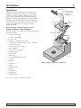
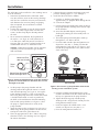
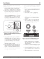
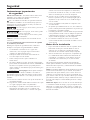
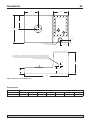
See Figure 1 for the basic plumbing layout.
Purchase Separately:
2 - 2” x Close Nipples
1 - 2” Slip Union
1 - 2” Slip 90° Elbow
Adapter
Foam
Gasket
Check Valve
Cord
Grommet
Pipe Grommet
Discharge Pipe
5159 1005
Figure 1: Piping Components and Layout.

Installation 5
For parts or assistance, call Flotec Customer Service at 1-800-365-6832
The Add-a-Jon can be installed as a free-standing unit or
it can be enclosed.
1. Determine the location of the Add-a-Jon. Make
sure you will have access to the existing discharge
and vent lines. Make the necessary measurements,
and determine the necessary fittings and piping
that are required. Be sure to observe all local
plumbingcodes.
2. Put the tank in position. It must be level to within
1/8”overitsentirelength.Makesurethatnails,
screws, or other sharp objects do not puncture
thetank.
3. For an enclosed installation, the flat portion of
thetankis5-3/8”high,soitwillfitbetween2”
x6”floorjoists.Notethatyouwillneedtocut
onejoist(with16”centers)andputheadersinto
accommodatethe24-1/4”widthofthetank.
NOTICE: A floor-flange-extender seal kit (purchase
separately) must be used for this type of under-
floorinstallation .
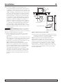
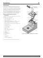
4. Set the pump in the pump chamber with the
discharge toward the right back corner as viewed
from the toilet opening (see Figure 2). Line up the
pumpdischargewiththe3”holeinthetanklid,
then swing the pump so that the vertical float switch
is shielded (from solids) as much as possible by
the baffle in the tank between the toilet mounting
hole and the pump chamber (see Figure 2). Shim
the pump as required to make it steady in the
pumpchamber.
5. Apply the foam gasket (see Repair Parts, Key No. 5)
to the flange of the pump chamber. For best results,
overlaptheendsofthegasketabout1/2”.
6. Placethepipegrommetinthe3”holeinthepump
chamber lid; this is the discharge seal. See Figure 3
for correct orientation.
7. Lubricate the pipe grommet with soapy water and
pushthedischargepipe(2”x32”)throughit.
8. Install the lid on the tank as follows.
A.Pushthe2”dischargepipedownuntil
approximately16”projectsdownthroughthelid.
B. Glue on the adapter.
C. Pull the pump and switch power cords up out of
the pump chamber and hang them over the edge
of the chamber.
D. Screw the threaded adapter into the pump
discharge by rotating the lid assembly until it is
hand tight.
E. Thread the pump and switch power cords up
throughthe2-1/2”holeinthelid.
F. Insert the cords into the split cord grommet (see
Repair Parts, Key No. 3), making sure that the
cord grommet is right side up (see Figure 3) and
outside the pump chamber. Leave yourself some
slack in the cord.
G. Push the lid down into position on the pump
chamber. Start bolts in the four corners of the lid
to keep it in position on the pump chamber.
H. Tighten the discharge pipe into the pump
discharge with a strap wrench. Do not press the
cord grommet into the lid yet.
I. Installandtightenalllidboltswitha7/16”
wrench (see Repair Parts, Key Nos. 6, 7).
J. Press the cord grommet into the lid.
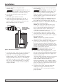
Center Pump Discharge
Under Discharge Port in Lid
Top of
Tank
Pump
Switch
Baffle
Make sure Float
does not hit baffle
3“
Vent
Figure 2: Center the pump discharge under the discharge
grommet in the lid; make sure the switch does not hit
the baffle in the tank.
NOT TO SCALE
Pipe
Grommet
Cord
Grommet
Lip is up
Pump Chamber
Figure 3: Cross-section of pump chamber lid and seals
showing correct orientation of seals.

Installation 6
For parts or assistance, call Flotec Customer Service at 1-800-365-6832
9. Glueonehalfofthe2”slipuniontothe
dischargepipe.
Fire and explosion hazard. PVC glue is
highly flammable. Do not use near fire or flame, and
follow glue manufacturer’s instructions carefully.
10. Glue the other half of the union to one of the
closenipples.
11.Gluebothnipplesintothe90°elbow.
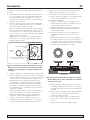
12. Attach the check valve (Repair Parts, Key No. 1)
to the close nipple that does not have the union
attached. Make sure the flange on the check valve
body is toward the pump (see Figure 4).
13. Assemble the union. Make sure that the elbow/check
valve alignment with existing plumbing is correct.
14.Installa2”or3”ventpipe(checkyourlocal
plumbingcode)inthe3”NPTthreadedventporton
thepumpchamber.Youcanusea3”threadedpipe
orgluetheventpipetoamaleadapter(3”ventpipe)
or2”slipx3”NPTreducerbushing(2”ventpipe),
and then thread the assembly into the vent port on
the pump chamber.
15. Connect the discharge pipe and vent pipe into the
house plumbing.
Risk of flooding. Vent this unit directly
to atmosphere (or through the existing house vent
pipe) according to national and local plumbing
codes. An automatic or mechanical vent device will
not work with this system. The toilet will not flush
unless properlyvented.
16A. If you are not attaching any additional fixtures to
the unit, skip to Step 20. If an additional fixture is
being added to your installation, go to Step 16B.
16B.Markthecenterofa3”diameterholeononeofthe
three sides of the pump chamber.
NOTICE: The center of this hole must be at least
6-1/2”abovethebottomofthetank,asshownin
Fig.6. If you intend to add more than one extra
fixture, mark a hole center as above for each
additional drain line. Each center must be at least
6-1/2”abovethebottomofthetank.
17. After choosing the spot(s) for the hole(s), lightly
center punch hole centers on the pump chamber.
18.Foreachcenteryouhavemarked,cuta3”diameter
hole with a hole saw.
NOTICE: To avoid leaks, the hole’s maximum
diametermustbe3”.Donotgooversize.
19.Lubricatea2”pipegrommetwithsoapywaterand
pushitintothe3”holefromStep18.Lubricate
the fixture drain pipe and push it through the pipe
grommet into the pump chamber. The pipe must not
interfere with the operation of, nor touch, the pump
or switch. Repeat for all drain lines.
Risk of electrical shock. Make sure the
pump is unplugged before beginning step 20.
20.Fillthetanktoadepthofapproximately4”(check
this with a tape measure through the opening where
the toilet is to be installed). Plug in the pump and
continue filling the tank.
The pump should start before the water level reaches
4-1/2”.Ifnot,unplugthepump,slidetheupper
rubber stop down the float rod and retest.
Ifthepumpstartsbefore3-1/4”,unplugthepump,
slide the upper rod stop higher up the float rod and
retest. The pump must start when the water level is
between3-1/4”and4-1/2”.
21. Check the tank for leaks. Attach the cord to the
discharge or vent pipe. Do not leave excess
cord inside the tank, as it may interfere with the
pump’soperation.
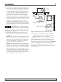
Not to scale.
Wiring omitted
for clarity.
Direction of Flow
Figure 4: Check valve installation.

Installation 7
For parts or assistance, call Flotec Customer Service at 1-800-365-6832
22. Your local or state plumbing code may require you
totestthesystemwitha“10footwatercolumntest”.
If so, make certain the pump chamber lid screws
are tightened down properly and that the lid gasket
isseated.Plugthe4”diametertoiletopening(in
the top of the tank) with an expandable plumber’s
plug (available at hardware stores). Also plug any
other openings in the system except the highest one
(normally the top of the vent stack). Make sure that if
the system is tied in to existing vents, drains, sewers,
toilets, etc., that any openings in these system
components are also plugged securely. The system
can now be tested per code requirements. Consult
your local code officials for more information about
this test.
Risk of flooding. Risk of damage to floor
and possible flooding. The tank and lid will expand with
the water column pressure while being tested. If you are
installing the tank under the floor, complete the testing
before the floor is installed.
23. Install the long studs and nuts (Repair Parts, Key
No. 10) that are used to fasten the toilet to the tank
orsubfloor.
NOTICE: To tighten the studs, thread both nuts onto
onestud,thenusethe1/2”wrenchtotightenthe
upper nut. The nuts should jam on the stud and turn
it into the threaded hole in the tank. Remove the
nuts and repeat for the second stud.
NOTICE: A standard floor flange is not required.The
position of the toilet must be determined to allow
the stud to be inserted in the correct holes. Install the
wax ring. Be sure to align the studs for installation
of the toilet bowl in the desired direction. (i.e., If the
vent and discharge pipe are to be installed behind
the wall to one side of the Add-a-Jon, you can turn
the toilet sideways on the tank top so that the flush
tank is flat against the wall – see Figure 5).
24. Install the wax toilet bowl seal(s) at the hole on
top of the tank and install the toilet following the
instructions from the wax seal package.
NOTICE: Do not use a wax seal having a flange that
extendsintothetank;itmaycauseclogging.Ifa1/2”
or1/4”floorisinstalledoverthetank,theappropriate
floor flange extender seal kit must be used. See NOTICE:
Floor Seal. Hook up the water line to the toilet. Turn
on the water and fill the toilet tank. Test for leaks,
flush the toilet, and allow the pump to cycle to ensure
properoperation.
Toilet Mounted straight on tank
Toilet rotated 90° on tank
Toilet
Mounting
Bolts
Toilet Mounting Bolts
Access
Hatch
Wall
Wall
Figure 5: Alternate Positions for Mounting Toilet.

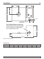
Installation 8
For parts or assistance, call Flotec Customer Service at 1-800-365-6832
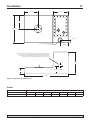
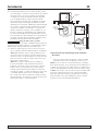
3“ NPT Spinweld
Vent Fitting
7-7/16”
2-7/16”
39-5/8”
5-3/8”
19-1/4”
Min. 6-1/2”
14-1/2”
12-5/8”
12”
24-1/4”
Cut 3” hole with holesaw to run drain line
from an additional fixture into tank. Center
of hole must be at least 6-1/2” above bottom
of tank. Use grommet to seal pipe where it
runs into tank. Be sure to support pipe to
take its weight off side of tank.
Figure 6: Add-a-Jon Dimensions.
Performance
Gallons of Water Pumped per Minute at Specified feet of Lift
Lift in Feet (m) 18 (5.5) 14 (4.3) 12 (3.7) 10 (3.1) 8 (2.4) 6 (1.8) 4 (1.2)
Gallons per Minute 0 35 (132) 47 (178) 60 (227) 70 (265) 80 (303) 92 (348)

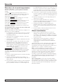
Troubleshooting 9
For parts or assistance, call Flotec Customer Service at 1-800-365-6832
Troubleshooting information for pump only. For other
questions or problems, please call FLOTEC Customer
Service at 1-800-365-6832.
Risk of electrical shock. Always unplug
the pump before handling it or making any adjustments.
Always wear rubber boots when there is water on
the floor and you must unplug the pump or make
anyadjustments.
Risk of infections from pathogens in
pumped effluent. Wear rubber gloves when removing the
pump from the tank and soak it in chlorine bleach for at
least an hour before working on it or servicing it.
NOTICE: An automatic thermal overload protects the
motor. Running the pump dry may overheat the motor
and activate the overload protector until the motor cools.
Pump does not run or just hums.
1. Line fuse or circuit breaker may be off, blown
orloose.
2. Water level in tank may be too low to activate
automatic float.
3. Power cord plug may not be making contact
inreceptacle.
4. If all symptoms check OK, motor is probably
defective; replace pump.
Pu mp runs but delivers no water or only small amount
ofwater.
1. Check valve may be installed backward. Make sure
flapper will open away from pump (see Figure 4).
2. Discharge gate valve, if used, may be closed.
3. Pump may be air locked. Start and stop several times
by plugging and unplugging cord. Check vent hole
in pump case for plugging.
NOTICE: The pump has a small air vent hole in the
pump body to let out trapped air. If this hole becomes
plugged, the pump may air lock. To break the air lock,
clear the hole with a small screwdriver.
As a secondary precaution in installations of this
type,drilla1/8”holeinthedischargepipeinsidethe
tank below the check valve. The check valve should
be mounted horizontally above the pump discharge.
Do not put the check valve directly into pump
dischargeopening.
NOTICE: In tanks where the pump is operating daily, air
locking rarely occurs.
4. The pump may be trying to lift water too high. The
pump cannot deliver water higher than 15’ (vertical
lift (a long horizontal piping run may reduce the
available lift due to friction in the pipe).
5. The inlet, impeller or pump body may be plugged
up. Unplug the pump; Put on rubber gloves, remove
the pump from the chamber, soak it in chlorine
bleach for at least one hour, and clean it out.
6. The pump impeller may be partially clogged, causing
the motor to run slowly, resulting in motor overload.
Unplug the pump; Put on rubber gloves, remove the
pump from the chamber, soak it in chlorine bleach
for at least one hour, and clean it out.
Th e fuse blows or the circuit breaker trips when the
pump starts.
1. The pump inlet may be clogged. Unplug and remove
the pump and clean out openings.
2. The impeller or pump body may be plugged or
partially plugged. Unplug the pump; Put on rubber
gloves, remove the pump from the chamber, soak it
in chlorine bleach for at least one hour, and clean
itout.
3. The pump impeller may be partially clogged, causing
the motor to run slowly, resulting in motor overload.
Unplug the pump; Put on rubber gloves, remove the
pump from the chamber, soak it in chlorine bleach
for at least one hour, and clean it out.
4. The fuse size or circuit breaker is too small.
5. Defective motor: call FLOTEC customer service at
1-800-365-6832.
Th e motor runs for a short time, then stops. After a
short time it starts again. This indicates tripping
overload caused by symptom shown.
1. The inlet, impeller or pump body may be plugged or
partially plugged. Unplug the pump; Put on rubber
gloves, remove the pump from the chamber, soak it
in chlorine bleach for at least one hour, and clean
itout.
2. The pump impeller may be partially clogged, causing
the motor to run slowly, resulting in motor overload.
Unplug the pump; put on rubber gloves, remove the
pump from the chamber, soak it in dilute chlorine
bleach for at least one hour, and clean it out.
3. Defective motor: call FLOTEC customer service at
1-800-365-6832.

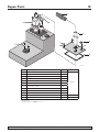
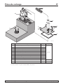
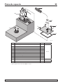
Repair Parts 10
For parts or assistance, call Flotec Customer Service at 1-800-365-6832
Key Part Description Qty. Part No.
• Installation Hardware Kit (Incl. Key Nos. 1,2,3,4,5,6,7,8,9) 1
PKG 450
1 Check Valve 1
2 2”x32”Schedule40PVCPipe 1
3 Cord Grommet 1
4 2”Adapt-A-FlexPipeGrommet 2
5 1/2”FoamGasketMaterial 1
6 Flat Washers–.320 I.D. 20
7 1/4”–20x5/8”HexHeadBolts 20
8 2”NPTx2”SlipAdapter 1
9 5/16”x2”StudsandNuts 2
10 Pump 1 FPSE9050
•† Wax Ring (Boxed) 1
•Notillustrated.
†Purchaselocally.SeeNOTICE: Floor Seal
1
2
3
4
5
8
6
7
5149 1005
10
9
Page is loading ...
Page is loading ...
Page is loading ...
Page is loading ...
Page is loading ...
Page is loading ...
Page is loading ...
Page is loading ...
Page is loading ...
Page is loading ...
Page is loading ...
Page is loading ...
Page is loading ...
Page is loading ...
Page is loading ...
Page is loading ...
Page is loading ...
Page is loading ...
-
 1
1
-
 2
2
-
 3
3
-
 4
4
-
 5
5
-
 6
6
-
 7
7
-
 8
8
-
 9
9
-
 10
10
-
 11
11
-
 12
12
-
 13
13
-
 14
14
-
 15
15
-
 16
16
-
 17
17
-
 18
18
-
 19
19
-
 20
20
-
 21
21
-
 22
22
-
 23
23
-
 24
24
-
 25
25
-
 26
26
-
 27
27
-
 28
28


Ask a question and I''ll find the answer in the document
Finding information in a document is now easier with AI
in other languages
- français: Flotec FP450C Mode d'emploi
- español: Flotec FP450C Guía del usuario
Related papers
-
Flotec E3375TLT Owner's manual
-
-
-
-
-
-
-
Flotec E5005TLT Owner's manual
-
-
Other documents
-
Sharper Image Motion-Activated Flushable Wipe Maker Owner's manual
-
 CountyLine CLW550 Owner's manual
-
Delta C41903T-WH Installation guide
-
Pentair DP233110V-01 User manual
-
Niagara Conservation 77000WHAI1 Installation guide
-
-
 Foremost TL-2100-W Installation guide
-
Foremost LL-1930-BI Operating instructions
-
Simer 2207C Owner's manual
-

