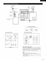
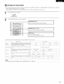
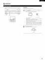
Denon AVR-1802 Owner's manual
- Category
- AV receivers
- Type
- Owner's manual
This manual is also suitable for

AV SURROUND RECEIVER
AVR- 1802/882
OPERATING INSTRUCTIONS
MODE D'EMPLOI
I I
DENOt
FOR ENGLISH READERS PAGE 2 ~ PAGE 48, 94, 95
• We greatly appreciate your purchase of this unit.
• To be sure you take maximum advantage of all the
features this unit has to offer, read these instructions
carefully and use the set properly. Be sure to keep this
manual for future reference should any questions or
problems arise.
"SERIAL NO.
PLEASE RECORD UNIT SERIAL NUMBER ATTACHED TO
THE REAR OF THE CABINET FOR FUTURE REFERENCE"
POUR LES LECTEURS FRANCAIS PAGE 2, 49 ~ PAGE 95
• Nous vous remercions pour I'achat de cet appareil.
• Pour 6tre sQr de profiter au maximum de toutes les
caracteristiques qu'offre cet appareil, lire avec soin ces
instructions et bien utiliser I'appareil. Toujours
conserver ce mode d'emploi pour s'y referer
ulterieurement en cas de question ou de probleme.
"NO. DE SERIE
PRIERE DE NOTER LE NUMERO DE SERIE DE L'APPAREIL
INSCRIT A L'ARRIERE DU COFFRET DE FA(_ON A POUVOIR
LE CONSULTER EN CAS DE PROBLEME."

• SAFETY PRECAUTIONS
_RISK OF ELECTRIC SHOCKI"'mA
DO NOT OPEN
CAUTION: TO REDUCE THE RISK OF ELECTRIC SHOCK,
DO NOT REMOVE COVER (OR BACK). NO
USER-SERVICEABLE PARTS INSIDE. REFER
SERVICING TO QUALIFIED SERVICE
PERSONNEL.
The lightning flash with arrowhead symbol, within an
equilateral triangle, is intended to alert the user to the
presence of uninsulated "dangerous voltage" within the
product's enclosure that may be of sufficient magnitude to
constitute a risk of electric shock to persons.
The exclamation point within an equilateral triangle is intended
to alert the user to the presence of important operating and
maintenance (servicing) instructions in the literature
accompanying the appliance.
WARNING: TO REDUCE THE RISK OF FIRE OR ELECTRIC
SHOCK, DO NOT EXPOSE THIS APPLIANCE
TO RAIN OR MOISTURE.
CAUTION
TO PREVENT ELECTRIC SHOCK, MATCH WIDE BLADE OF PLUG
TO WIDE SLOT, FULLY INSERT.
ATTENTION
POUR EVITER LES CHOCS ELECTRIQUES, INTERODUIRE LA
LAME LA PLUS LARGE DE LA FICHE DANS LA BORNE
CORRESPONDANTE DE LA PRISE ET POUSSER JUSQU' AU
FOND.
This device complies with Part 15 of the FCC Rules. Operation is subject to
the following two conditions: (1) This device may not cause harmful
interference, and (2) this device must accept any interference received,
including interference that may cause undesired operation.
This Class B digital apparatus meets all requirements of the Canadian
Interference-Causing Equipment Regulations.
Cet appareil num6rique de la classe B respecte toutes les exigences du
Reglement sur le mat6riel brouilleur du Canada.
• NOTE ON USE / OBSERVATIONS RELATIVES A L'UTILISATION
• Avoid high temperatures.
Allow for sufficient heat dispersion when
installed on a rack.
• Eviter des temperatures elev6es.
Tenir compte d'une dispersion de chaleur
suffisante lors de Finstallation sur une 6tag_re.
• Handle the power cord carefully.
Hold the plug when unplugging the cord.
• Manipuler le cordon d'alimentation avec
pr6caution.
Tenir la prise Iors du debranchement du
cordon.
• Keep the set free from moisture, water, and
dust.
• Proteger Fappareit contre I'humidit6, Feau et la
poussi6re.
• Unplug the power cord when not using the set
for long periods of time.
• Debrancher le cordon d'aIimentation Iorsque
Fappareit n'est pas utitise pendant de Iongues
p6riodes.
* (For sets with ventilation holes)
• Do not obstruct the ventilation holes.
• Ne pas obstruer les trous d'aeration.
• Do not let foreign objects in the set.
• Ne pas laisser des objets etrangers dans
Fappareil.
• Do not let insecticides, benzene, and thinner
come in contact with the set.
• Ne pas mettre en contact des insecticides, du
benz_ne et un diluant avec Fappareit.
• Never disassemble or modify the set in any
way.
• Ne jamais demonter ou modifier I'appareil
d'une maniere ou d'une autre.
2

1.
2.
3.
4.
5.
6.
6A.
7.
8.
SAFETY INSTRUCTIONS
Read Instructions - All the safety and operating
instructions should be read before the appliance is
operated.
Retain Instructions -The safety and operating instructions
should be retained for future reference.
Heed Warnings - All warnings on the appliance and in the
operating instructions should be adhered to.
Follow Instructions - All operating and use instructions
should be followed.
Water and Moisture - The appliance should not be used
near water - for example, near a bathtub, washbowl,
kitchen sink, laundry tub, in a wet basement, or near a
swimming pool, and the like.
Carts and Stands -The appliance should be used only with
a cart or stand that is recommended by the manufacturer.
An appliance and cart
combination should be
moved with care.
Quick stops, excessive
force, and uneven
surfaces may cause
the appliance and cart
combination to overturn.
Wall or Ceiling Mounting - The appliance should be
mounted to a wall or ceiling only as recommended by the
manufacturer.
Ventilation - The appliance should be situated so that its
location or position does not interfere with its proper
ventilation. For example, the appliance should not be
situated on a bed, sofa, rug, or similar surface that may
block the ventilation openings; or, placed in a built-in
installation, such as a bookcase or cabinet that may impede
the flow of air through the ventilation openings.
9. Heat - The appliance should be situated away from heat
sources such as radiators, heat registers, stoves, or other
appliances (including amplifiers) that produce heat.
10. Power Sources -The appliance should be connected to a
power supply only of the type described in the operating
instructions or as marked on the appliance.
11. Grounding or Polarization - Precautions should be taken so
that the grounding or polarization means of an appliance is
not defeated.
12. Power-Cord Protection - Power-supply cords should be
routed so that they are not likely to be walked on or
pinched by items placed upon or against them, paying
particular attention to cords at plugs, convenience
receptacles, and the point where they exit from the
appliance.
14. Cleaning - The appliance should be cleaned only as
recommended by the manufacturer.
15. Power Lines - An outdoor antenna should be located away
from power lines.
16.
Outdoor Antenna Grounding - If an outside antenna is
connected to the receiver, be sure the antenna system is
grounded so as to provide some protection against voltage
surges and built-up static charges. Article 810 of the
National Electrical Code, ANSl/NFPA 70, provides
information with regard to proper grounding of the mast
and supporting structure, grounding of the leadqn wire to
an antenna-discharge unit, size of grounding conductors,
location of antenna-discharge unit, connection to grounding
electrodes, and requirements for the grounding electrode.
See Figure A.
17. Nonuse Periods - The power cord of the appliance should
be unplugged from the outlet when left unused for a long
period of time.
18. Object and Liquid Entry - Care should be taken so that
objects do not fall and liquids are not spilled into the
enclosure through openings.
19. Damage Requiring Service - The appliance should be
serviced by qualified service personnel when:
A. The power-supply cord or the plug has been damaged;
or
B. Objects have fallen, or liquid has been spilled into the
appliance; or
C. The appliance has been exposed to rain; or
D. The appliance does not appear to operate normally or
exhibits a marked change in performance; or
E. The appliance has been dropped, or the enclosure
damaged.
20. Servicing - The user should not attempt to service the
appliance beyond that described in the operating
instructions. All other servicing should be referred to
qualified service personnel.
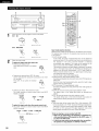
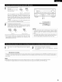
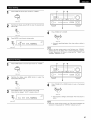
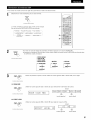
EXAMPLEOt'2##_AOROONDI._
AS PER NATIONAL
ELECTRICAL CODE ANTENNA
LEAD IN
WIRE
GROUND
CLAMP
ANTENNA
DISCHARGE UNiT
(NEC SECTION 8t0-20)
GROUNDING CONDUCTORS
EC SECTION 810-21)
POWER SERVICE GROUNDING
='1_ ELECTRODE SYSTEM
(NEC ART 250, PART H)
NEC - NATIONAL ELECTRICAL CODE
3

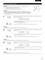
• INTRODUCTION
Thank you for choosing the DENON A/V Surround receiver. This remarkable component has been engineered to provide superb surround sound
listening with home theater sources such as DVD, as well as providing outstanding high fidelity reproduction of your favorite music sources.
As this product is provided with an immense array of features, we recommend that before you begin hookup and operation that you review the
contents of this manual before proceeding.
TABLE OF CONTENTS
[] Before Using .............................................................................................. 4
[] Cautions on Installation .............................................................................. 5
[] Cautions on Handling ................................................................................. 5
[] Features ...................................................................................................... 5
[] Part Names and Functions ..................................................................... 6, 7
[] Read this first ............................................................................................. 8
[] Setting up the Speaker Systems ................................................................ 8
[] Connections ......................................................................................... 9~15
[] Using the Remote Control Unit ................................................................ 16
[] Setting up the system ....................................................................... 17~21
[] Remote Control Unit .......................................................................... 22~24
[] Operation ............................................................................... 25~29
[] Surround ............................................................................................. 30~34
[] DSP Surround Simulation ......................................................... 35~39
[] Listening to the Radio ........................................................................ 40~42
[] Last Function Memory ............................................................................. 43
[] Initialization of the Microprocessor .................................................... 43
[] Additional Information ........................................................................ 44~46
[] Troubleshooting ........................................................................................ 47
Specifications ........................................................................................... 48
List of Preset Codes .................................................................................. 94, 95
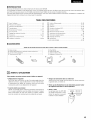
• ACCESSORIES
Check that the following parts are included in addition to the main unit:
(_ Operating instructions ............................................................................ 1
Warranty ( for North America model only ) ............................................ 1
(_ Service station list ................................................................................... 1
(_ Remote control unit (RC-897) ................................................................. 1
_) R6P/AA batteries .................................................................................... 2
AM loop antenna .................................................................................... 1
(_ FM indoor antenna .................................................................................. 1
(_ FM antenna adaptor ................................................................................ 1
®
%
®
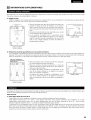
!-_ BEFORE USING
Pay attention to the following before using this unit:
• Moving the set
To prevent short circuits or damaged wires in the connection cords,
always unplug the power cord and disconnect the connection
cords between all other audio components when moving the set.
• Before turning the power operation switch on
Check once again that all connections are proper and that there are
not problems with the connection cords. Always set the power
operation switch to the standby position before connecting and
disconnecting connection cords.
• Store this instructions in a safe place.
After reading, store this instructions along with the warranty in a
safe place.
• Note that the illustrations in this instructions may differ from
the actual set for explanation purposes.
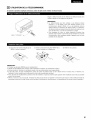
%/,AUX terminal
The AVR-1802's front panel is
equipped with a V. AUX terminal.
Remove the cap covering the
terminal when you want to use
it.
........................... j
- --_ t_
4

[_ CAUTIONS ON INSTALLATION
Noise or disturbance of the picture may be generated if this unit or
any other electronic equipment using microprocessors is used near a
tuner or TV.
If this happens, take the following steps:
• Install this unit as far as possible from the tuner or TV.
• Set the antenna wires from the tuner or TV away from this unit's
power cord and input/output connection cords.
• Noise or disturbance tends to occur particularly when using indoor
antennas or 300 _/ohms feeder wires. We recommend using
outdoor antennas and 75 _/ohms coaxial cables.
For heat dispersal, leave at least 0.3 ft (10 cm) of space between
the top, back and sides of this unit and the wall or other
components.
0.3 ft (t0 cm) or more
eye CAUTIONS ON HANDLING
• Switching the input function when input jacks are not
connected
A clicking noise may be produced if the input function is switched
when nothing is connected to the input jacks. If this happens,
either turn down the MASTER VOLUME control or connect
components to the input jacks.
• Muting of PRE OUT jack, HEADPHONE jack and SPEAKER
terminals
The PRE OUT jack, HEADPHONE jack and SPEAKER terminals
include a muting circuit. Because of this, the output signals are
greatly reduced for several seconds after the power operation
switch is turned on or input function, surround mode or any other
set-up is changed.
If the volume is turned up during this time, the output will be very
high after the muting circuit stops functioning. Always wait until
the muting circuit turns off before adjusting the volume.
• Whenever the power operation switch is in the STANDBY
state, the apparatus is still connected on some AC line
voltages.
Please be sure to unplug the cord when you leave home for,
say, a vacation.
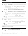
!-_ FEATURES
1. Dolby Pro Logic II decoder
Dolby Pro Logic ][][is a new format for playing multichannel audio
signals that offers improvements over conventional Dolby Pro
Logic. It can be used to decode not only sources recorded in
Dolby Surround but also regular stereo sources into five channels
(front left/right, center and surround left/right). In addition, various
parameters can be set according to the type of source and the
contents, so you can adjust the sound field with greater precision.
2. Dolby Digital decoder
Dolby Digital, a digital discrete system in which the different
channels are completely independent, recreates "three-
dimensional" sound fields (sounds with a sense of distance,
movement and position) with no crosstalk between channels for
greater reality. In addition, the 5 channels (excluding the 0.1
channel for low frequency effects) have a playback range
extending to 20 kHz, the same as the range of CDs, thus resulting
in clearer, more richly expressive sound.
3. DTS (Digital Theater Systems) decoder
DTS provides up to 5.1 channels of wide-range, high fidelity
surround sound, from sources such as laser disc, DVD and
specially-encoded music discs.
4. High performance DSP simulates 7 sound fields
Playback is possible in 7 surround modes: 5-channel Stereo, Mono
Movie, Rock Arena, Jazz Club, Video Game, Matrix and Virtual.
You can enjoy a variety of sound effects for different movie
scenes and program sources even with stereo sources not in
Dolby Surround.
5. Personal Memory Plus function
Personal Memory Plus is an advanced version of Personal
Memory. With Personal Memory Plus, the set automatically
memorizes the surround mode, channel volume, surround
parameters, etc., for each of the separate input sources.
6.
7.
Remote control unit with pre-memory function
This unit comes with a remote control unit equipped with a pre-
memory function. The remote control command codes for
DENON remote controllable AV components as well as for DVD
players, LD players, video decks, TVs, etc., of other major
manufacturers are prestored in the memory.
6CH EXT. IN jack
This unit is equipped with 6CH EXT. IN jacks for use with audio
formats of the future.
5

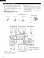
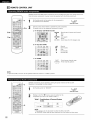
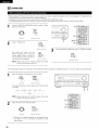
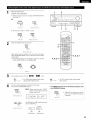
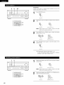
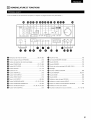
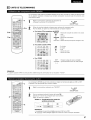
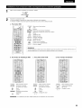
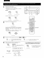
PART NAMES AND FUNCTIONS
• For details on the functions of these parts, refer to the pages given in parentheses ().
DUD
Power operation switch .............................................. (18, 25, 40)
Headphones jack (PHONES) .................................................... (28)
Preset stations selector buttons .............................................. (42)
_l_ SPEAKER A/B buttons ................................................. (25, 28, 43)
INPUT MODE button ................................................... (26, 29, 33)
ANALOG button ................................................................ (26, 29)
EXT. IN button ................................................................... (26, 29)
_t_ CINEMA EQ button ................................................................. (33)
_1_ TONE DEFEAT button ............................................................. (27)
_) VIDEO SELECT button ............................................................ (28)
_!_ V. AUX INPUT jacks ............................................................. (4, 10)
SURROUND MODE button ................................... (27, 31, 33, 38)
_) SURROUND PARAMETER button ..................................... (31, 38)
_) SELECT knob .................................................. (27, 30, 31, 33, 38)
_!_ TONE CONTROL button .......................................................... (27)
_) CH VOL button ........................................................................ (30)
_!_ MASTER VOLUME control ...................................................... (27)
STATUS button ........................................................................ (28)
_) DIMMER button ...................................................................... (28)
_) Master volume indicator (VOLUME LEVEL) ............................ (27)
_1 Display
_) TUNING UP/DOWN button ..................................................... (41)
_1 MEMORY button ............................................................... (40, 42)
_1 MODE button .......................................................................... (41)
BAND button ........................................................................... (41)
_} SIGNAL indicators .................................................................... (27)
INPUT mode indicators ............................................................ (27)
_) Remote control sensor (REMOTE SENSOR) .......................... (19)
_) Power operation indicator
Input source selector buttons ..................................... (26, 31, 33)
6

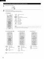
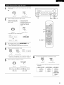
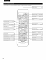
• For details on the functions of these parts, refer to the pages given in parentheses (
INPUT MODE button (26, 29)
SURROUND MODE
button ........................ (27, 30, 31, 33, 36)
System buttons (TAPE, VCR)
buttons ......................................... (22, 24)
I VIDEO SELECT button ....................... (28)
SYSTEM (SYSTEM SET UP) I
buttons ............................................... (18)
I
I Cursor buttons ....................... {17,32,36) I
I Test tone button ................................. (30) I
I System buttons (TV) .......................... (24) I
I
I
Y
I
I
I
I
I
I
I
f CD MD/CDR_
| I
__ _ _,.IPHONO""'d6"" "gqg_5_" I
V, AUX VCR-1 VCR-2 TV/DBS _
c_Dc_ oD.__j
INPUTMODE_CDR/TAPE
'.._._._.
_i_iii¸iii!iii!i!i¸iii!!i,
I
_,STER
voL i
2', !
Remote control signal
transmitter ......................................... (16)
I Mode selector switch (17, 22, 23) I
I
I POWER buttons .................... (23,24,25) I
Input source selector
buttons ................................... (26, 31, 33)
Preset stations select
buttons ......................................... (22, 42)
System buttons
(CD, MD/CDR, DVD/VDP) ............ (22, 24)
SURROUND (SURROUND PARAMETER)
button .............................. (31, 33, 34, 36)
Master volume control
buttons ............................................... (27)
I MUTlNGbutton ................................. (28) I
--I STATUS button ................................... (28) I
7

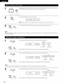
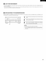
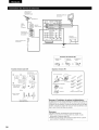
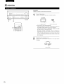
READ THIS FIRST
This AV Surround Receiver must be setup before use. Following these steps.
[
Next, insert the batteries into the remote control unit.
Step 3
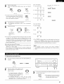
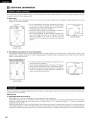
SETTING UP THE SPEAKER SYSTEMS
• Speaker system layout
Basic system layout
• The following is an example of the basic layout for a system consisting of six speaker systems and a television monitor:
Center speaker system
r
Front speakersystems
Set these atthe sides of the TVor screen with
their front surfaces as flush with the front of the
screen as possible.
Surround speaker systems
8

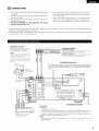
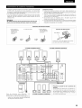
r_ CONNECTIONS
• Do not plug in the power cord until all connections have been
completed.
• Be sure to connect the left and right channels properly (left with
left, right with right).
• Insert the plugs securely. Incomplete connections will result in
the generation of noise.
• Use the AC OUTLETS for audio equipment only. Do not
use them for hair driers, etc.
• Note that binding pin plug cords together with power cords or
placing them near a power transformer will result in generating
hum or other noise.
• Noise or humming may be generated if a connected audio
equipment is used independently without turning the power
of this unit on. If this happens, turn on the power of this unit.
• Analog recording of signals input to the AVR-1802 in digital format is not possible. To record in analog, also connect the analog signals of the
player to the AVR-1802% analog input terminals.
• The AVR-1802's OPTICAL OUT terminal is an optical digital output terminal for connection of a CDR recorder, MD recorder or other digital
recording device. Use it for digital recording.
I Connecting a turntable I
Connect the turntable's output cord to this
unit's PHONO jacks, the L (left) plug to the L
jack, the R (right) plug to the right jack.
NOTE:
This unit cannot be used with MC
cartridges directly. Use a separate head
amplifier or step-up transformer.
If humming or other noise is generated when
the ground wire is connected, disconnect the
ground wire.
Tumtable
(MM cartridge)
Ground wire
w_
LINE OUT
I Ioo_O_l
Decoders with 6-channel
analog outputs, etc.
Z
u.I
Z
INPUT OUTPUT
R L R L
Tape deck or CD recorder
[ Connecting a tape deck I
Connections for recording:
Connect the tape deck's recording input jacks (LINE IN or REC) to this
unit's tape recording (OUT) jacks using pin plug cords.
Connections for playback:
Connect the tape deck's playback output jacks (LINE OUT or PB) to
this unit's tape playback (IN) jacks using pin plug cords.
{ Connecting the pre-out jacks 1
Use these jacks if you wish to connect external power amplifier(s) to increase the
power of the front and center channels, or for connection to powered !oudspeakers.
Connect the internal amplifier's subwoofer to the subwoofer terminal. (Refer to
page 14.)
AC 120V, 60Hz
°
%oo
,, ,,
L__._=_=_..... "1
SpEAKERSYSTEMS _MACOUTLFSi
® FRONT ® CENTER SURReUNO AC_eV_
® (k ® _ ® _ TOTSWITCHEDA
I I
[ Connecting the AC OUTLETS 1
AC OUTLETS
SWITCHED
(total capacity - 120 W (1 A.))
The power to these outlets is turned on and off in conjunction with the POWER switch on the main
unit, and when the power is switched between on and standby from the remote control unit.
No power is supplied from these outlets when this unit's power is at standby. Never connect
equipment whose total capacity is above 120 W (1 A.)
NOTE:
Only use the AC OUTLETS for audio equipment Never use them for hair driers, TVs or other
electrical appliances.
9

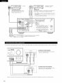
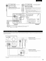
To connect the video signal, connect using a 75 _/ohms video signal cable cord. Using an improper cable can result in a drop in sound quality.
IConnecting a TV game equipment I
• Connect the TV game equipment's output jacks to
this unit's V. AUX INPUT lacks.
I Connecting a video camera equipment I
• Connect the video camera equipment's output
jacks to this unit's V. AUX INPUT lacks.
"_ The V. AUX terminal is covered with a cap. Remove this cap in order to use the terminal. (See page 4 for instructions on removing the cap.)
10

AUDIO VIDEO DIGITAL
OUT
R OUT L OUT OPTECAL
TV or DBS tuner
I Connecting a TV/DBS tuner I
TV/DBS
• Connect the TV's or DBS tuner's video output jack (VIDEO OUTPUT)
to the _ (yellow) TV/DBS IN jack using a 75 _z!ohms video
coaxial pin plug cord.
• Connect the TV's or DBS tuner's audio output jacks (AUDIO
OUTPUT) to the _ TV/DBS IN jacks using pin plug cords.
5
O
o
AUDIO.......G.... I
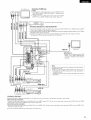
out _ [] _EZD DVD player or video disc player (VDP)
R°°TLOUT...... _ oo::j_::
I Connecting a DVD player or a video disc player VDP I
• Connect the DVD player's (video disc player's) video output jack (VIDEO OUTPUT) to the _ (yellow) DVD/VDP
IN jack using a 75 _z!ohms video coaxial pin plug cord.
• Connect the DVD player's (video disc player's) analog audio output jacks (ANALOG AUDIO OUTPUT) to the
DVD/VDP IN jacks using pin plug cords.
• For better sound quality, we recommend using the DVD player with digital rather than analog connections.
DVD players and VDP can also be connected to the VCR terminals.
( VIDEO OUT
€ _ VIDEO IN
R OUT L R _N L
@
@
@
VIDEO OUT
VIDEO IN _ Monitor TV
MONITOR OUT
• Connect the TV's video input jack (VIDEO
INPUT) to the _ MONITOR OUT
jack using a 75 _/ohms video coaxial pin
plug cord.
@
@
@
@
@
@
@
@
@
@
@
NOTE:
Connection of the video disc Player Equipped with Dolby Digital RF
(AC-3RF) Output Jack.
• Please use a commercially available adaptor when connecting the
Dolby Digital RF (AC-3RF) output jack of the video disc player to
the digital input jack.
Please refer to the instruction manual of the adapter when making
connections.
[ Connecting a video decks ]
• There are two sets of video deck (VCR) jacks, so two video decks can be connected for simultaneous recording or video copying.
Video input/output connections:
• Connect the video deck's video output jack (VIDEO OUT) to the _ (yellow) VCR-1 IN jack, and the video deck's video input jack (VIDEO IN) to the
(yellow) VCR-1 OUT jack using 75 _z!ohms video coaxial pin plug cords.
Connecting the audio output jacks:
• Connect the video deck's audio output jacks (AUDIO OUT) to the _ VCR-1 IN jacks, and the video deck's audio input jacks (AUDIO IN) to the _ VCR-1
OUT jacks using pin plug cords.
•_ Connect the second video deck to the VCR-2 jacks in the same way.
11

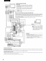
• When marking connections, also refer to the operating instructions of the other components.
• A note on the S input jacks
The input selectors for the S inputs and pin jack inputs work in conjunction with each other.
• Precaution when using S-jacks
This unit's S-jacks (input and output) and video pin jacks (input and output) have independent circuit structures, so that video signals input from
the S-jacks are only output from the S-jack outputs and video signals input from the pin jacks are only output from the pin jack outputs.
When connecting this unit with equipment that is equipped with S-jacks, keep the above point in mind and make connections according to the
equipment's instruction manuals.
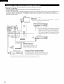
Monitor TV
SPEAKERSYST_ I ACOUTL_S I
_ _ _R_T ® _TER SURROUND / /AC120V_Hz
o o
I
Connecting a monitor TV ]
MONITOR OUT
• Connect the TV's or DBS tuner's S video input (S-VIDEO INPUT) to the
MONITOR OUT jack using a S jack connection cord.
Video deck 1
I==== .... _ ol O
I _ I1_1 --
[ Connecting the video decks ]
• Connect the video deck's S output jack (S-OUT) to the _
VCR-1 IN jack and the video deck's S input jack (S-IN) to the
VCR-1 OUT jack using S jack connection cords.
• Connect the video deck's S output jack (S-OUT) to the
VCR-2 IN jack and the video deck's S input jack (S-IN) to the
OHHHHOOOOOHHH_ _ VCR-2 OUT jack using S jack connection cords.
Video deck 2
I _ I1_1 --
HOOOOOOHH j ,-.,-.,-.,-. .... @ @j O
_oooooo_ooooo_ooooo_ooooooo_oo_
TV or satellite broadcast tuner
I/[11' a'v''-'
• Connect the TV's or DBS tuner's S video
output jack (S-VIDEO OUTPUT) to the
_ TV/DBS IN jack using an S jack
- === connection cord.
| |
DVD player, VDP, etc.
[ Connecting a DVD player or video disc player (VDP) ]
DVD/VDP
• Connect the DVD player's or video disc player's S-Video output jack
to the S-VIDEO DVD/VDP IN jack using an S-Video connection cord.
Connect the components' audio inputs and outputs as described on page 11. ]
12

DIRECTION OF
BROADCASTING
STATION
75 _/ohms
COAXIAL
CABLE
}_FM ANTENNA
_ EEDER
CABLE
FM ANTENNA
ADAPTER
(An Accessory)
FM INDOOR ANTENNA
(An Accessory)
AM LOOP
ANTENNA
(An Accessory)
ANTEa_AZRMIN_LS_ # [_] _ CDR/
L00P_
_ 2
EXT_N AUO_O O_G_TAL VlOEO
AM OUTDOOR
ANTENNA
GROUND
AM loop antenna assembly
_Remove the vinyl tie
and take out the
connection line.
a. With the antenna
on top any stable
surface.
Connect to the AM
antenna terminals.
Bend in the reverse
direction.
Mount
b. With the antenna
attached to a
wall.
Installation hole
Mount on wall, etc.
Connection of AM antennas
1. Push the lever. 2. insert the 3. Return the lever.
conductor.
=>
FM antenna adapter assembly
Open the cover
PULL
C
PUL
ANTENNA ADAPTER
_ REMOVE
CLAMP
SHUT
3C 2v 5C-2V
75 _/ohms COAXIAL CABLE
Note to CATV system installer:
This reminder is provided to call the CATV system installer's
attention to Article 820-40 of the NEC which provides guidelines
for proper grounding and, in particular, specifies that the cable
ground shall be connected to the grounding system of the
building, as close to the point of cable entry as practical.
Notes:
• Do not connect two FM antennas simultaneously.
• Even if an external AM antenna is used, do not disconnect the
AM loop antenna.
• Make sure AM loop antenna lead terminals do not touch metal
parts of the panel.
13

• Connect the speaker terminals with the speakers making sure that like
polarities are matched (_) with @, _ with _). Mismatching of polarities will
result in weak central sound, unclear orientation of the various instruments,
and the sense of direction of the stereo being impaired.
• When making connections, take care that none of the individual conductors
of the speaker cord come in contact with adjacent terminals, with other
speaker cord conductors, or with the rear panel.
NOTE:
NEVER touch the speaker terminals when the power is on.
Doing so could result in electric shocks.
Speaker Impedance
• When speaker systems A and B are use separately, speakers with an
impedance of 6 to 16 _Uohms can be connected for use as front speakers.
• Be careful when using two pairs of front speakers (A + B) at the same time,
since use of speakers with an impedance of 12 to 16 _Uohms.
• Speakers with an impedance of 6 to 16 _Uohms can be connected for use
as center and surround speakers.
• The protector circuit may be activated if the set is played for long periods of
time at high volumes when speakers with an impedance lower than the
specified impedance are connected.
Connecting the speaker cords
1. Loosen by turning 2. Insert the cord. 3. Tighten by turning
counterclockwise, clockwise.
Connecting banana plugs
banana plug
Turn clockwise to tighten, then insert the
banana plug.
[FRONT SPEAKER SYSTEMS I [FRONT SPEAKER SYSTEMS I [CENTER SPEAKER SYSTEM I
System B System A
i _EXX_N AUII_O OI_ITAL VIDEO AOREIS_I_ CENTERs_ _
Connection jack for subwoofer with built-in
amplifier (super woofer), etc.
•_ To achieve Dolby Digital (AC-3) playback
effect, use a unit that can sufficiently
reproduce frequencies of under 80 Hz.
4-
__i!il hen connecting speakers
s placed near a TV or video monitor, the
he screen may be disturbed by the
agnetism. If this should happen, move
away to a position where it does not
+ - have this effect.
SURROUND SPEAKER SYSTEMS ]
14

This unit is equipped with a high-speed protection circuit. The purpose of this circuit is to protect the speakers under
circumstances such as when the output of the power amplifier is inadvertently short-circuited and a large current flows,
when the temperature surrounding the unit becomes unusually high, or when the unit is used at high output over a long
period which results in an extreme temperature rise.
When the protection circuit is activated, the speaker output is cut off and the power supply indicator LED flashes. Should
this occur, please follow these steps: be sure to switch off the power of this unit, check whether there are any faults with
the wiring of the speaker cables or input cables, and wait for the unit to cool down if it is very hot. Improve the ventilation
condition around the unit and switch the power back on.
If the protection circuit is activated again even though there are no problems with the wiring or the ventilation around the
unit, switch off the power and contact a DENON service center.
The protector circuit may be activated if the set is played for long periods of time at high volumes when speakers with
an impedance lower than the specified impedance (for example speakers with an impedance of lower than 4 O/ohms)
are connected. If the protector circuit is activated, the speaker output is cut off. Turn off the set's power, wait for the set
to cool down, improve the ventilation around the set, then turn the power back on.
15

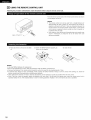
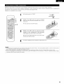
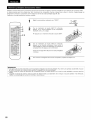
_'_ USING THE REMOTE CONTROL
UNIT
Following the procedure outlined below, insert the batteries before using the remote control unit.
30°
Approx
Point the remote control unit at the remote control sensor as shown
on the diagram at the left.
NOTES:
• The remote control unit can be used from a straight distance of
approximately 23 feet/7 meters, but this distance will shorten or
operation will become difficult if there are obstacles between the
remote control unit and the remote control sensor, if the remote
control sensor is exposed to direct sunlight or other strong light, or
if operated from an angle.
• Neon signs or other devices emitting pulse-type noise nearby may
result in malfunction, so keep the set as far away from such
devices as possible.
(_ Press as shown by the arrow and slide
off.
(_) Insert the R6P/AA batteries properly, as
shown on the diagram.
(_ Close the lid.
NOTES:
• Use only R6P/AA batteries for replacement.
• Be sure the polarities are correct. (See the illustration inside the battery compartment.)
• Remove the batteries if the remote control transmitter will not be used for an extended period of time.
• If batteries leak, dispose of them immediately. Avoid touching the leaked material or letting it come in contact with clothing, etc. Clean the
battery compartment thoroughly before installing new batteries.
• Have replacement batteries on hand so that the old batteries can be replaced as quickly as possible when the time comes.
• Even if less than a year has passed, replace the batteries with new ones if the set does not operate even when the remote control unit is
operated nearby the set. (The included battery is only for verifying operation. Replace it with a new battery as soon as possible.)
16

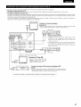
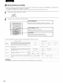
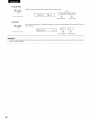
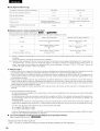
SETTING UP THE SYSTEM
• Once all connections with other AV components have been completed as described in "CONNECTIONS" (see pages 9 to 15), make the
various settings described below on the display.
These settings are required to set up the listening room's AV system centered around the this unit.
Set the slide switch to "AUDIO".
CD MD/CDR
AUDIO_ VIDEO
2
Use the following buttons to set up the system:
i
_ :MUTING
c3
t SYSTEM SETUP button
Press this to display the system setup on the display.
I CURSOR buttons (A, T, _1, I_)
Press this change what appears on the display.
i SELECT button
Press this to switch the display.
Also use this button to complete the setting.
t
I
• System setup items and default values (set upon shipment from the factory)
Speaker
Configuration
System setup
input the combination of speakers in your system and their
corresponding sizes (SMALL for regular speakers, LARGE for full-size,
fuIFrange) to automatically set the composition of the signals output
from the speakers and the frequency response.
Subwoofer Mode This selects the subwoofer speaker for playing deep bass
signals.
Delay_me
Digital Input
Channel Level
This parameter is for optimizing the timing with which the audio
signals are produced from the speakers and subwoofer according to
the listening position.
This assigns the digital input jacks for the different input
sources.
Digital
Inputs
Input
source
This adjusts the volume of the signals output from the speakers and
subwoofer for the different channels in order to obtain optimum
effects.
Front Sp.
Large
Front & Subwoofer
12 ft (3.6 m)
COAXIAL OPT[CAL-I
DVD/VDP TV/DBS
Front L Front R Subwoofer
OdB OdB OdB
Default settings
Center Sp. Surround Sp.
Small Small
Subwoofer mode = Normal
Center
12 ft (3,6 m)
OPTICAL-2
CDR/TAPE
Center
0dB
Surround L & R
10 ft (3.0 m)
Surround L Surround R
0riB 0dB
NOTE:
• The system setup is not displayed when "HEADPHONE ONLY" is selected.
Sub Woofer
Yes
w
w
w
w
17

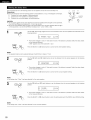
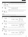
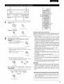
1
2
ON / STANDBY
(Main unit)
Check that all the components are correct, then press the POWER operation switch on the main unit or
the POWER button on the remote control unit to turn on the power.
AVR/AVC
%
(Remote control unit)
Press the SYSTEM button to enter the setting.
:+:SVSTEM SET UF' ]
NOTE: Please make sure the "AUDIO" position of the slide switch on the remote control unit.
Press the SELECT or _ (down) button to switch to the speaker configuration set up.
NOTE:
Press the SYSTEM button again to finish system set up. System set up can be finished at any time. The changes to the settings made up to
that point are entered.
1
Use the _ (left) and _ (right) buttons to select your front speaker type.
_--_ (Initial)
IJ. FROH[ L.i:::iRGE ] _
EEl OE]
(left) button (right) button
Press the SELECT or _ (down) button to switch to the center speaker setting.
2
Use the _ (left) and _ (right) buttons to select your center speaker type.
:2 CENTER SMi:::ii.........
(Initial)
c_ c_
(left) button (right) button
Press the SELECT or C_ (down) button to switch to the surround speaker setting.
NOTE:
• When "Small" has been selected for the front speakers, "Large" cannot be selected for the center speaker.
3
Use the _ (left) and _ (right) buttons to select your surround speaker type.
3 :iii;URR. :iii;Mi:::ii.........
(Initial)
(left) button (right) button
Press the SELECT or _ (down) button to switch to the subwoofer setting.
18

NOTE:
• When "Small" has been selected for the front speakers, "Large" cannot be selected for the surround speakers.
4
Use the I_D (left) and _ (right) buttons to select your subwoofer setting.
:::i. ::::: i:ii"ii"i i:::'i:::'i:;:: : -":"':....
E_D
(left) button
(right) button
Press the SELECT or C_ (down) button to enter the settings and switch to the SUBWOOFER MODE
setting.
• Parameters
Large ...... Select this when using speakers that can fully reproduce low sounds of below 80 Hz.
Small ...... Select this when using speakers that cannot reproduce low sounds of below 80 Hz with sufficient volume. When this setting is
selected, low frequencies of below 80 Hz are assigned to the subwoofer.
None ...... Select this when no speakers are installed.
Yes/No .... Select "Yes" when a subwoofer is installed, "No" when it's not installed.
NOTE:
Select "Large" or "Small" not according to the physical size of the speaker, but according to the bass reproduction capacity at 80 Hz. If you cannot
determine the best setting, try comparing the sound when set to "Small" and when set to "Large", at a level that will not damage the speakers.
Caution:
In case the subwoofer is not used, be sure to set "Subwoofer = No", or the bass sound of front channel is divided to subwoofer channel and
not reproduced in some mode.
1
Use the _ (left) and _ (right) buttons to select the Subwoofer mode.
_U _k, (Initial)
.5 Si.-.i MO[?E NORM ' '
(33
(left) button
OD
(right) button
Press the SELECT or (_D (down) button to enter the setting and switch to the SPEAKER DISTANCE
setting.
NOTES:
-- Assignment of low frequency signal range --
• The signals produced from the subwoofer channel are LFE signals (during playback of Dolby Digital or DTS signals) and the low frequency
signal range of channels set to "SMALL" in the setup. The low frequency signal range of channels set to "LARGE" are produced from those
channels.
-- Subwoofer mode --
• The subwoofer mode setting is only valid when "LARGE" is set for the front speakers and "YES" is set for the subwoofer in the "Speaker
Configuration" settings (see pages 18, 19}.
If "SMALL" is set for the front speakers or "NO" is set for the subwoofer, the subwoofer mode setting does not affect playback of low
frequency signal range.
• When the "+MAIN" playback mode is selected, the low frequency signal range of channels set to "LARGE" are produced simultaneously
from those channels and the subwoofer channel.
In this playback mode, the low frequency range expand more uniformly through the room, but depending on the size and shape of the room,
interference may result in a decrease of the actual volume of the low frequency range.
• When the "NORM" playback mode is selected, the low frequency signal range of channels set to "LARGE" are only produced from those
channels. In this playback mode there tends to be little interference of the low frequency range in the room.
• Try playing the music or movie source and select the playback mode providing the stronger low frequency range sound.
19

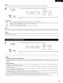
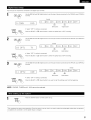
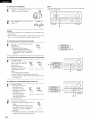
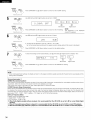
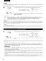
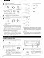
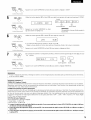
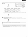
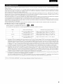
Input the distances from the listening position to the speakers and set the surround delay time.
Preparations:
Measure the distances from the listening position to the speakers (L1 to L3 on the diagram at the right).
L_: Distance from center speaker to listening position
L2: Distance from front speakers to listening position
L3: Distance from surround speaker to listening position
CAUTION:
•_ Set the center speaker at the same distance from the front speakers (left and right) or the subwoofer,
or so that the difference in distance (L2 - L1} is 5 feet or less.
•_ Set the surround speakers (left and right) at the same distance from the front speakers (left and right)
or the subwoofer, or so that the difference in distance (L2 - L3) is 15 feet or less.
FL Center FR
t' l
L2 _, _tJ Listening
SL SR
1
Use the _ (left) and _ (right) buttons to set the distance from the front speakers and subwoofer to the
listening position.
I'::: ......................... :i 2 i:]
..... i'- i'°::i"-i i ....::::0W . "i:'- :
• The number changes in units of 1 foot each time one of the buttons is pressed. Select the value closest
to the measured distance.
("/SW" appears only when subwoofer = yes.)
Press the SELECT or (_D (down) button to switch to the center speaker setting.
NOTE:
• The speaker distance can be adjusted between 0 and 60 feet in steps of 1 foot.
2
Use the (_D (left) and _ (right) buttons to set the distance from the center speakers to the listening
position.
' CENTER :L2-i:--i::]
• The number changes in units of 1 foot each time one of the buttons is pressed. Select the value closest
to the measured distance.
Press the SELECT or I_D (down) button to switch to the surround speaker setting.
NOTE:
• No setting when "None" has been selected for the center speaker.
3
Use the I_D (left) and I_ (right) buttons to set the distance from the surround speakers to the listening
position.
l:iii: :iii;URR. :i.0-i:i::]
• The number changes in units of 1 foot each time one of the buttons is pressed. Select the value closest
to the measured distance.
Press the SELECT or (_D (down) button to enter the setting and switch the DIGITAL input (COAX) setting.
NOTE:
• No setting when "None" has been selected for the surround speakers.
2O
Page is loading ...
Page is loading ...
Page is loading ...
Page is loading ...
Page is loading ...
Page is loading ...
Page is loading ...
Page is loading ...
Page is loading ...
Page is loading ...
Page is loading ...
Page is loading ...
Page is loading ...
Page is loading ...
Page is loading ...
Page is loading ...
Page is loading ...
Page is loading ...
Page is loading ...
Page is loading ...
Page is loading ...
Page is loading ...
Page is loading ...
Page is loading ...
Page is loading ...
Page is loading ...
Page is loading ...
Page is loading ...
Page is loading ...
Page is loading ...
Page is loading ...
Page is loading ...
Page is loading ...
Page is loading ...
Page is loading ...
Page is loading ...
Page is loading ...
Page is loading ...
Page is loading ...
Page is loading ...
Page is loading ...
Page is loading ...
Page is loading ...
Page is loading ...
Page is loading ...
Page is loading ...
Page is loading ...
Page is loading ...
Page is loading ...
Page is loading ...
Page is loading ...
Page is loading ...
Page is loading ...
Page is loading ...
Page is loading ...
Page is loading ...
Page is loading ...
Page is loading ...
Page is loading ...
Page is loading ...
Page is loading ...
Page is loading ...
Page is loading ...
Page is loading ...
Page is loading ...
Page is loading ...
Page is loading ...
Page is loading ...
Page is loading ...
Page is loading ...
Page is loading ...
Page is loading ...
Page is loading ...
Page is loading ...
Page is loading ...
Page is loading ...
-
 1
1
-
 2
2
-
 3
3
-
 4
4
-
 5
5
-
 6
6
-
 7
7
-
 8
8
-
 9
9
-
 10
10
-
 11
11
-
 12
12
-
 13
13
-
 14
14
-
 15
15
-
 16
16
-
 17
17
-
 18
18
-
 19
19
-
 20
20
-
 21
21
-
 22
22
-
 23
23
-
 24
24
-
 25
25
-
 26
26
-
 27
27
-
 28
28
-
 29
29
-
 30
30
-
 31
31
-
 32
32
-
 33
33
-
 34
34
-
 35
35
-
 36
36
-
 37
37
-
 38
38
-
 39
39
-
 40
40
-
 41
41
-
 42
42
-
 43
43
-
 44
44
-
 45
45
-
 46
46
-
 47
47
-
 48
48
-
 49
49
-
 50
50
-
 51
51
-
 52
52
-
 53
53
-
 54
54
-
 55
55
-
 56
56
-
 57
57
-
 58
58
-
 59
59
-
 60
60
-
 61
61
-
 62
62
-
 63
63
-
 64
64
-
 65
65
-
 66
66
-
 67
67
-
 68
68
-
 69
69
-
 70
70
-
 71
71
-
 72
72
-
 73
73
-
 74
74
-
 75
75
-
 76
76
-
 77
77
-
 78
78
-
 79
79
-
 80
80
-
 81
81
-
 82
82
-
 83
83
-
 84
84
-
 85
85
-
 86
86
-
 87
87
-
 88
88
-
 89
89
-
 90
90
-
 91
91
-
 92
92
-
 93
93
-
 94
94
-
 95
95
-
 96
96


Denon AVR-1802 Owner's manual
- Category
- AV receivers
- Type
- Owner's manual
- This manual is also suitable for
Ask a question and I''ll find the answer in the document
Finding information in a document is now easier with AI
in other languages
- français: Denon AVR-1802 Le manuel du propriétaire
Related papers
Other documents
-
Philips FR999/17 User manual
-
Sharp CD-DD4500 User manual
-
Sony Sony TAA1ES High-Resolution Audio Stereo Amplifier User manual
-
Yamaha RX-1130 Owner's manual
-
-
-
-
-
NAD 614 User manual
-