Craftsman 172.26729 Owner's manual
- Category
- Power tools
- Type
- Owner's manual
This manual is also suitable for

Owner's Manual
ICRAFTSMANI
31/4-1N. PLANER
Model No.
172.26729
CAUTION: Read, understand and follow
all Safety Rules and Operating Instructions
in this manual before using this product,
• SAFETY
• OPERATION
• MAINTENANCE
• ESPANOL,PAGINA 21
Sears, Roebuck and Co., Hoffman Estates, IL 60179 U.S.A.

J Z_ WARNING: BE SURE to read and understand all instructions.Failure J
to follow all ip_ructions listed below may result in electric shock, fire and/or
I
serious personal injury.
WORK AREA SAFETY
1. ALWAYS keep your work area clean and well IlL Cluttered and dark areas
Invite accidents.
2. DO NOT operate power tools In explosive atmospheres, such as In the
pm._e.nce of flammable liquids, gases, or dust. Power toolscreate sparks
wnucnmay ignitethe oustor Rimes.
3. ALWAYS keep bystanders, children and visitors away while operating a
power tool. Distractions can cause you to lose control.
ELECTRICAL SAFETY
1. Double Insulated tools ere equipped with e polarized plug (one blade Is
wider than the other). This plug will fit in a polarized outlet only one way.
If the plug does not fit fully into the outlet, reverse the plug. If It still
does not tit, contact a qualified electrician to Install a potarlzed outleL
DO NOT change or alter the plug In any way.
2. Double insulation [] eliminates the need for the three wire grounded power
cord and grounded power supply system. Applicable only to Class II
(double insulated) tools.
3. Before plugging in the tool BE SURE that the outlet voltage supplied is
within the voltage marked on the tool's data plate. DO NOT use =AC only"
rated tools with a DC power supply.
4. ALWAYS avoid body contact with grounded surfaces, such as pipes,
radiators, ranges and refrigerators. There is an increased dsk of electric
shock if your body is grounded.
5. If operating the power tool In damp locations Is unavoidable, ALWAYS
use a Ground Fault Circuit Interrupter to supply power to your tool.
ALWAYS wear electrician's rubber gloves and footwear In damp
conditions.
6. DO NOT expose power tools to rein or wet condlUons. Water entering a
power tool will increase the dsk of electric shock.
7. DO NOT abuse the cord. NEVER use the cord to carry the tools or pull
the p.lug from the outlet. Keep cord away from heat, o11,sharp edges or
movnng parts. Replace damaged cords Immediately. Damaged cords
increase the risk of electric shock.
8. When operating a power tool outside, ALWAYS use an outdoor extension
cord marked "W-A" or _ These cords are rated for outdoor use and reduce
the risk of electric shock.
NOTE: The extension cord must have adequate wire size AWG
(American Wire Gauge) for safe, efficient use. Smaller gauge wires have
greater capacity (16 gauge wire has more capacity than 18 gauge wire).
3

PERSONAL SAFETY
1. ALWAYS stay alert, watch what you are doing and use common sense
when operatlng s power tool. DO NOT use tool while tired or under the
influence of drugs, alcohol or medication. A momentof inattentionwhile
operatingpowertools may result in seriouspersonal injury.
2. ALWAYS dress properly. DO NOT wear loose clothing or Jewelry. Pull
back long hair. Keep _/our hair, clothing and gloves away from moving
parts. Looseclothing,jewelry or long haircan be caught in moving parts.
3, ALWAYS avoid accidental starting. BE SURE switch Is in the "Off"
position before plugging in. DO NOT carry toolswith yourfinger onthe
switch.Carrying toolswithyourfinger on the switch or pluggingin toolsthat
have the switch in the"On"positioninvitesaccidents.
4. ALWAYS remove adjusting keys or wrenches before turning the tool on.
.Awrench or a key that isleft attached to a rotating part ofthe toolmay result
in personal injury.
5. DO NOT overreach. ALWAYS keep proper footing and balance at all
times. Proper lootingand balance enables better controlofthe toolin
unexpected situations.
6. ALWAYS use safety equipment. Always wear eye protection. Dust mask,
non-skidsafety shoes,hard hat, or hearing protectionmustbe usedfor
appropriate conditions.
TOOL USE AND CARE SAFETY
1. ALWAYS use clamps or other practical ways to secure and support the
work piece to a stable platform. Holdingthe work by handor againstyour
body is unstableand may teedto lossofcontrol.
2. DO NOT force the tool. Use the correct tool for your application.
The correcttoolwilldo the job betterand safer at the rate for whichitis
designed.
3. DO NOT use the tool if the switch does not turn it "On" or "Off", Anytool
that cannot be controlledwiththe switchisdangerous and mustbe repaired.
4. ALWAYS disconnect the plug from the power source before making any
adjustments, changing accessories or storing the tool. Suchpreventive
safety measures reducethe risk ofstartingthe toolaccidentally.
5. ALWAYS store Idle tools out of the reach of children and other
untrained persons. Toolsare dangerousin the handsof untrainedusers.
6. ALWAYS maintain tools with care. Keep cutting tools sharp and clean.
Properly maintainedtoolswithsharp cuttingedges are lesslikelyto bind and
are easier to control.
7. ALWAYS check for misallgnment or binding of moving ports, breakage
of parts, and any other condition that may affect the tool's operation.
If damaged, have the tool serviced before using. Many accidentsare
caused by poorly maintained tools.
4

TOOLUSEANDCARESAFETYcont.
/_ WARNING: USEOFACCESSORIESTHATARENOT RECOMMENDED I
FOR USEWITHTHISTOOLMAYCREATEA HAZARDOUSCONDITION.
I
8. ALWAYS use only accessorles that are recommended for this tool.
Accessories that may be suitablefor one tool can become hazardous when
used on anothertool.
SERVICE SAFETY
I. If any part of this planer is missing or should break, bend, or fail in any
way; or should any electrlcal component fall to perform properly:
ALWAYS shutoffthe powerswitchand remove theplaner plugfrom the
powersourceand have the missing,damaged or tailed parts replaced
BEFORE resuming operation.
2. When servicing a tool, ALWAYS use only Identical replacement parts.
Follow Instructions In the maintenance section of this manual. Use of
unauthorizedparts may create a riskof electricshockor injury.
3. Toolservice MUST BE performedonlyby a Sears Partsand Repair Center.
Service or maintenanceperformedby unqualifiedpersonnelcouldresultin a
riskof injury.
ADDITIONAL RULES FOR SAFE OPERATION
,/_ WARNING: BE SURE to readand understandall instructions.Failure I
tofollow all instructionslisted below may resultinelectricshock,fire and/or
I
serious personal injury.
1. Know your power tool. Read operator's manual carefully. Learn the
applications and limitations as well as the specific potential hazards
related to th s tool. Followingthis rule willreducethe nsk ofelectric shock,
fire or serious injury.
2. ALWAYS wear safety glasses or eye shields when using this planer.
Everyday eyeglasses have only impact-resistant lenses; they are NOT
safety glasses. Followingthis rulewill reducetherisk of serious personal
injury.
3. ALWAYS protect your lungs.Wear a face mask or dust mask if the
operation is dusty. Followingthis rule willreducethe riskofserious
personal injury.
4. ALWAYS protect your hearing.Wear hearing protection during
extended periods of operation. Followingthisrulewillreduce the risk of
seriouspersonalinjury.
5. ALWAYS inspect the tool cords periodically and if damaged have them
repaired at your nearest Sears Service Center or other Authorized
Service Facility. ALWAYS be aware of the cord location. Followingthis
rule will reduce the risk of electric shock or fire.

ADDmONAL RULES FOR SAFE OPERATION cont.
6. ALWAYS check for damaged parts. Before further use of the toot,
a guard or other part that is damaged should be carefully checked to
determine If it will operate properly and perform its intended function.
Check for misallgnment or binding of moving pads, breakage of parts,
and any other condition that may affect the tool's operation. A guard or
other part that is damaged should be properly repaired or replaced at
a Sears Service Center. Followingthis rulewillreduce the riskofa ectr c
shock,fire or seriousinjury.
7. DO NOT abuse the cord. NEVER use the cord to carry the tools or pull
the plug from the outlet. Keep cord away from heat, oil, sharp edges or
moving parts. Replace damaged cords immediately. Damaged cords
increasethe risk ofeleCtriCshock. Followingthis rulewillreducethe riskof
electricshock or fire.
8. ALWAYS make sure that your extension cord Is in good condition.
When using an extension cord be sure to use one that is heavy
enough to carry the current that your tool will draw. Awire gauge
(AWG) of at least 14 is recommendedforan extensioncord25 feet or less
in length.When workingoutdoorsALWAYS use an extensioncordthatis
suitablefor outdoor use.The cord'sjacket willbe marked WA.
Smatter gauge wires, have greater capacity (16 gauge wire has more
capacity than 18 gauge wire). An undersizedcordwillcause a drop in
line voltage, resultingin lossof powerand overheating.
9. ALWAYS inspect and remove all nails from lumber before planing,
Followingthis rulewillreduce the riskof seriouspersonalinjury.
10. DO NOT use the tool while tired or under the Influence of drugs,
alcohol or any medication. Followingthis rule willreduce the riskof
electricshock,fire or serious persona_iniury.
11. SAVETHESE INSTRUCTIONS. Refer to them frequently and use them
to instruct others who may use this tool. If someone borrows this tool,
make sure they have these instructions also.
6

ADDITIONAL RULES FOR SAFE OPERATION cont.
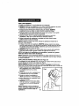
/_ WARNING: The operationof any planer can result
in foreign objectsbeingthrownintoyour eyes,whichcan
resultin severeeye damage. Beforebeginning powertool
operation,ALWAYS wear safetygogglesor safetyglasses
with sideshieldand a fullface shield when needed.
We recommendAWide VisionSafety Mask for useover
eyeglassesor standardsafety glasses with side shield,
available at Sears RetailStores.
L_WARNING: Some dust particles created by power sanding, sawing,
grinding, drilling and other construction jobs contain chemicals known to
cause cancer, birth defects or other reproductive harm. Some examples
of these chemicals are:
• Lead from lead-based paints.
• Crystallinesilica from bricks and cement and other masonryproducts.
• Arsenic and chromium from chemically-treated lumber.
Your risk from these exposures varies, depending upon how often you do this
type of work.To reduce your exposure to these chemicals:
• Work in a well-ventilated area.
• Work with approved safety equipment such as those dust masks that are
specially designed to filter out microscopic particles.
The label on your tool may include the following symbols.
V........................................................................... Volts
A.......................................................................... Amperes
Hz........................................................................ Hertz
W.......................................................................... Watts
rain ...................................................................... Minutes
........................................................................ Alternating current
.... ................................................................... Direct current
no ........................................................................ No-load speed
[] ........................................................................ Class II construction
.../rain .................................................................. Revolutions or
reciprocation per minute
Z_ ........................................................................ Indicates danger, warning
caution. It means attention!!!
Your safety is involved,
IMPORTANT! READ ALL INSTRUCTIONS
7

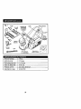
KNOWYOURPLANER(SeeFig.1)
Beforeattempting to use any tool, be ,suretofamiliarizeyourselfwith all the
operatingfeatures and safety instructions.
Yourplaner has many built-inconveniencefeatures for fast, efficientcutting.
It iscompact and lightweightfor easy,comfortableuse.The depth adjustment
knob isconveniently locatedat the front of the planer and allowseasy depth
adjustmentsfrom 0 to 1/8-in. to suityour needs.
Yourplaner uses reversible,double-edgedhardened steel carbide-tippedblades
that allow useon bothsides for longerbladelife.It includesedge guide for
accurate cuts on long or unevenwork pieces.The rabbetguide allowsyou to
make rabbetcuts up 15/16 in.deep.
Electrical Connection
Yourplaner has a precision-builtelectricmotorand itshouldonly beconnected
toa 120-volt, 60-Hz. power supply (normal household current). DO NOT
operate on directcurrent (DC).This largevoltage dropwillcause a lossof
powerthat witloverheatthe motor.If yoursaw does notoperate when plugged
intoan outletcheckthe powersupply.
Trigger Switch and On/Off Button
To turnon the planer press and hold theOn/Off buttonand squeezethe trigger
switch.When you are finished planing,release switchto shuttool off.
Adjustable Left or Right Dust / Chip Extraction
The dust/ chipchute can be adjusted forleftor rightextractionby turningthe
chute clockwiseor counterclockwise.
Base Plate Stand
Whenever you place the planer ontoa work surface,the rear of thebase plate
shouldbe elevated on thisstand.Thiswillhelp protectthe planer bladesfrom
damage and help preventthe blades from accidentallydamagingthe work
surface.As you begin to plane, this stand willhe pushedaway bythe work
surface.ALWAYS besure thatthe stand moveseasily on the base plate.

input
Cutting Width
Cutting Depth
Max. Rabbet Cut
Rating
No-Load Speed
7 Amps
3 1/4 in.
0 to l/B-in.
15/16-in.
120 volts, 60 Hz AC
12,000 RPM

I/Jk WARNING: YourplanershouldNEVERbeconnectedtopowersupply I
|
whenyouareassemblingparts,makingadjustments,changingbeltsorblades,
I
cleaningplaner,orwhennotin use,Disconnectingplanerwillpreventaccidental
startingthatcouldcauseseriousinjury.
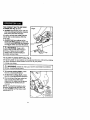
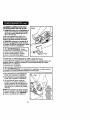
PREPARING FOR OPERATION
Yourplaner has a rear handle and frontassist handlefor ease of
operation.Theyprovide the two-hand operationwhichisnecessaryto maintain
propercontrolofthe planer.ALWAYS keep bothhandsclear of the bladesand
the cuttingarea.
ALWAYS usa bothhandswhen usingthe planer.Hold thefront handlewith
yourlefthand and the rear handlew_h yourrighthand (as shownin Fig.2).
This positionmakes yourplaner easier to handle and keepsyouclear ofthe
chip exhaust.
The work movingduringa cutcould resultin the lossof controlof the planer,
possiblycausingserious injury.
A !
ZL_ CAUTION: DO NOT plane toofast because this causesbuildup in I
the chipexhaust.Chip build-up restrictsair flow and cancausethe motorto
I
over heat.
Keep the cordaway from the cuttingarea. ALWAYS place the cord soitdoes
nothang on the workwhen you are makinga cut.
/_, DANGER: Ifthe cordhangs upon thework duringthecut, releasethe I
tdggerswitchimmediately.Unplugthe planerand checkthecordfor damage.
I
Ifthereisno damage, repositionthecordtopreventitfrom hangingup again.
Ifthecord has been damaged,haveitreplacedbefore usingyourplaner.
Z_ WARNING: Usingyourplaner witha damaged cordcouldcause I
electricalshockresulting in seriousinjury.
I
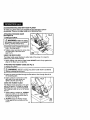
THE CORRECTWAYTO USEYOUR PLANER (See Fig. 2)
ALWAYS holdyourplaner as shownin Figure 2.
1. ALWAYS keep controlofyour planer.It makes cuttingeasier and safer,
as shownin Figure2.
2. To helpkeep control ALWAYS supportyourwork so the cutwillbe on
yourright.
3. ALWAYS clamp yourworkso it does not moveduringthe cut(see Figure2).
The work moving duringa cutcould resultinthe loss ofcontrolofthe planer,
possiblycausing serious injury.
The work movingduring a cut couldresultin the loss ofcontrolofthe planer,
possiblycausingserious injury.
10

THECORRECTWAYTOUSEYOUR
PLANER(SeeFig,2)cont.
4,ALWAYSoperatetheplanerwiththe
chipchuteexhaustturnedsoit points
away from yourface and eyes.
All visitorsshould wear safetyglasses
and be kept a safe distance from the
work area.
5, ALWAYS hold your planer so the
blades DO NOT come in contact with
the workpiece BEFORE you squeeze
the trigger switchand start the planer.
Z_ WARNING: Keep a firm
grip on the tool with both hands at
all times. Failure to do so could
result in loss of control leading to
possible serious injury.
TO ADJUST PLANING DEPTH (See Fig. 3)
The planing depth on yourplaner can be adjusted from 0 to 1/8 inch by rotating
the depth adjustment knob located on the front of your planer,
1. Unplug your planer.
I starting, causing serious injury.
Z_ WARNING: Failure to unplug your planer could result in accidental I
2. To increase cutting depth rotate
knob n a cockwisedirection.
3. To decrease cutting depth, rotate
knob ina counterclockwisedirection,
4. We recommend thatyou make test
cutsin scrap woodafter each
adjustmentto make sure the planer
is removingthe desired amount
of wood.
NOTE: To protect the blades during
storage, transporting and when not
in use, ALWAYS set the blade depth
adjustment to 0.
11

GENERAL CUTTING
1. Adjustplaner todesired depth.
2. ALWAYS grip the planer withyour left-handholdingthefront handleand your
righthandholdingthe top handle.
3, Place frontshoe fiaton the work piece,ALWAYS make sure thatthe blades
are nottouchingthe work piece.
4. Applypressureto thefront handle untilthe frontshoe isfiaton the work piece.
5. Pushthe On/Off buttonand Squeeze the triggerswitchto startthe planerand
allowthe motorto reach maximumspeed.
6. Holdthe planer firmlyand pushitsteadilyina forward directionontothe
workpiece.
NOTE: Ifyou desire a smoothcut, pushthe planer slowlyina forward direction.
7. Asyou reach theend ofyourdesired cut, ALWAYS applydownward
pressuretowardthe rear handle.Thiswillhelp keepthe rear sectionofthe
base in contactwiththe work pieceand help preventthe frontofthe planer
from dippingand gougingyourcut.
8. ALWAYS be carefulto avoidhittingnailsduringthe planingoperation
because thiscould nick, crack or otherwise damage the blades.
NOTE:The blades in your planer are reversible, so they can be rotated
until both sides are dull.
NOTE: We suggestthat you keepan extraset of bladeson hand, soyou can
replacethe blades in yourplaner when theyshow signsof becomingdull.
Always reverseor replaceblades in pairs.
EDGE PLANING / CHAMFERING (See Figure 4)
Yourplaner isdesigned with a groove inthe frontshoe.This grooveis for
chamferingthe edges ofboards (see Fig.4).
NOTE: ALWAYS make a practicecut on scrap woodtodetermine how
muchwood needs to be removedfrom the board BEFORE makingyour
actual cut.
1. Firmly holdthe rear handle of the
planer withyour lefthand and the top
handle with your right hand.
2. Place the groove on the planer on to
the surface to be cut.
3. Turn on planer and let it reach
full speed.
4. Slowly move planer onto work.
5. ALWAYS maintain downward
pressure on the planer to keep it flat
at the beginning and the end of the
work piece.
NOTE: Making several passes of more
shallow cuts will provide a smoother
cut and makes it easier to control
planer. 12
Fig. 4 ,/ //

ACCESSORIES INCLUDED WITH YOUR PLANER
To make yourplaner evenmore versatilewe have included2 special
accessories. They are an Edge Guide and a Rabbeting Plate.
ATTACHINGTHE EDGE GUIDE
(See Figure 5)
1. Unplugyourplaner.
I /_ WARNING: Failureto unplug I
yourplanercould resultinaccidental
starting,causingseriousinjury.
2. Insertthe screwprovidedthroughthe
hole in the edge guide.
3. Tighten screw securely into screw hole
on either side of the main shoe
(see Fig. 5).
USING THE EDGE GUIDE
The Edge Guide easily attaches to either side of the planer. It is ideal for
planing long and uneven boards.
1. When making cuts with the Edge Guide ALWAYS hold itfirmly against the
edge of the board you are planing.
ATTACHINGTHE RABBET GUIDE (See Fig. 6)
1. Unplug yourplaner.
/_ WARNING: Failureto unplugyourplanercouldresultin accidental I
starting,causingseriousinjury.
I
2. Insert the screw provided throughthe flat washer,then throughthe slot in
the rabbetingplate,
3. Insertscrew intoscrew holeon the
rightside ofthe main shoeand
tightensecurely (see Fig.6).
USING THE RABBET GUIDE
The Rabbet Guide attaches to the right
side of the planer. It is ideal for making
rabbeting cuts up to 15/16 inches thick.
The maximum width of cut is 15/16-inch
per cut.
1. When making a rabbet cut, ALWAYS
place the notch on the inside of the
main shoe firmly against the side of
the board (see Fig. 6).
2. ALWAYS press the Rabbet Guide
firmly against the top surface of the
board. 13
Nolch

TO ADJUSTTHE DEPTH OF RABBEt" CUT
1. Unplug yourplaner.
I /_ WARNING: Failureto unplugyourplanercouldresult in accidental istarting,causingseriousinjury.
2. Place planeron a flat board or work piece.
3. Loosen the screwand positionthe bottomsurfaceofthe Rabbet Guide above
the boardthe same distanceas the desired depthofcut.
4. Tightenscrew securely.
REPLACINGTHE BLADES (See Figures 7 to 9)
The blades in thisplaner are reversible,so when the bladesbecome dull,
theycan be reversed.
ALWAYS REPLACE OR REVERSETHE BLADES IN PAIRS.
DO NOT ATTEMPTTO SHARPEN THE BLADES.
NEVER OPERATE YOUR PLANER WITH ONLY ONE BLADE INSTALLED.
1. Unplug yourplaner.
I _, WARNING: Failuretounplugyourplanercouldresultinaccidental
starting,causingserious injury.
2. Place the planer upside down on the work bench. (See Fig. 7).
3. Use the wrench (included) to loosenthe 3 bolts that hold the blade to the
blade clamp.To loosen bolts, turn them approximately 1/2 turn in a clockwise
direction. (See Fig. 7).
4. Hold the blade clamp in position and use a piece of wood to slide the blade
out of blade clamp. (See Fig. 8).
5. Push down on blade guard when removing the blade from the blade clamp.
(See Fig. 8),
Fig. 8
of
Wood
Work
Bench
14

REPLACINGTHE BLADES (See Figures 7 to 9) conL
I Z_ CAUTION: Bladesare verysharp.ALWAYShandle bladesvery
carefullyFailureto do socouldresultin possibleseriousinjury.
NOTE: DO NOT remove the blade clamp.This couldalter the factory setting
for cuttingheight and bladeheight.
NOTE: DO NOT adjust the height
adjusting screws.
6. Place new blade or reverse existing
blade into blade clamp.(See Fig. 9),
7. Check to be sure blade is properly
positioned in blade clamp and the
blade edge is level with the base.
(See Fig. 9).
8, Securely re-tighten the 3 bolts.
9, Repeat the steps 3 through 8 above
to change or reverse the other blade.
10. Remove piece of wood from planer.
Z_ Warning: ALWAYS remove the piece of woodbeforestarting your J
planer.Failureto doso couldresult in the pieceofwoodbeing thrownfrom
I
yourplaner, causingpossibleseriousinjury.
USING THE LEFT OR RIGHT DUST / CHIP
EXTRACTION (See Figure 10)
The dust / chip chute can be adjusted for
left or right extraction. Turn chute clockwise
for extraction on the left side, or turn it
counterclockwise for extraction on the right
side.The arrow on the top of the chute
indicates the direction the chips will be
extracted.
15

SERVICE
I k WARNING: Preventativemaintenanceperformedby unauthorized
personnel mayresultIn misplacingof Internal wiresandcomponents,which
couldcausea serioushazard.
• All service that requires opening the planer MUST only be performed by a
Seam Service Center. All motor parts represent an important part of the
double insulation system and MUST only be serviced by a Sears Service
Center. Service performed by unqualified personnel could result in a risk of
injury.
• When servicing this tool, ALWAYS use only identical replacement parts.
Follow instructions in the Maintenance Section of this manual Use of
unauthorized parts or failure to follow Maintenance instructions may create a
risk of electrical shock or injury,
• Avoid solvents when cleaning plastic parts. Most plastics are susceptible to
damage from various types of commercial solvents and may be damaged by
their use. Use clean cloths to remove dirt, carbon dust, etc.
GENERAL
I Z_ WARNING: Toavoidaccidents,ALWAYSdisconnectthetcol fromthe
powersourceBEFOREcleaningorperforminganymaintenance.
All parts represent an important part of the double insulation system and shcu d
be serviced only at a Sears Service Center.
I _ WARNING: DONOTat anytimeletbrakefluids,gasoline,
pelroleum-basedproducts,penetratingoils,etc., comein contactwithplasticparts.
Theycontainchemicalsthat can damage,weakenordestroyplastic.
It is a knownfact that electric toolsaresubject to acceleratedwear and
possible premature failure when they are used to work on fiber glass boats and
sports cars, wallboard, speckling compounds or plaster. The chips and
grindings from these materials are highly abrasive to electrical tool parts, such
as bearings, brushes, commutators, etc.Consequently, it is not recommended
that this tool be used for extended work on any fiber glass material, wallboard,
spackling compound, or plaster. During any use on these materials, it is
extremely important that the tool iscleaned frequently by blowing with an air jet.
16

LUBRICATION
All ofthe bearingsin this tool are lubricatedwith a sufficientamount of
high-gradelubricantforthe lifeof the toolundernormal operatingconditions,
Therefore, no furtherlubricationisrequired.
I Z_ WARNING: ALWAYSwearsafetygogglesorsafetyglasseswithside Ishieldswhenusingthistoolorblowingdust.Ifoperationisdusty,alsoweara dustmask.
DOUBLE INSULATION
Doubleinsulationisa safrtyfeature in safety inelectricpowertools, that
eliminatesthe need forthe standard3-wire groundedpowercord. Allexposed
metal parts are isolatedfrom the internalmotorcomponentswith protecting
insulation.Doubleinsulatedtoolsdo not need to be grounded.
EXTENSION CORDS
Sears offersa largeselectionof extensioncordsthat helpextendyour working
range.
The use of any extension cord willcause some loss of power. To keep the loss
at a minimum and to preventoverheating, use an extension cord that is heavy
enough to carry the current that the tool willdraw,
A wire gauge (AWG) of at least 14 is recommended for an extension cord 25
feet or less in length. When working outdoors ALWAYS use an extension cord
that is suitable for outdoor use. The cord's jacket will be marked WA.
I Z_ CAUTION: Keepextensioncordsawayfrom thecuttingarea,and position
the cordso itwillnotgetcaughton lumber,tools,etc.duringthecuttingoperation.
I _ WARNING: Check extension cords before each use. Replace damaged
cords itimmediately. NEVER use a tool with a damaged cord because touching the
damaged area could cause electrical shock, resulting in serious injury.
BLADES
The blades foryour planer are currentlyavailable at yourlocal Sears Store.
I Z_ WARNING: The use of attachments or accessories that are not
recommended may be dangerous.
17

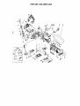
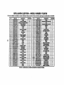
POWER PLANER - MODEL NUMBER 172.26729
The Model Numberwillbe foundonthe Nameplate.Alwaysmentionthe ModelNumberinallcorrespondenceregardingyourtool
,,,k
Part No.
SB19.0.02-00
SW55.58.0-00
SB19.0.15-00
SB19.0.05-00
ST05,07.21-00
SW56.12.0-00
SB19.0.21-00
SB19.0.07-00
SB19.0.22,-00
SB19.2.01-00
SB19.0.30-00
SB19.0.29-00
SB19.0.13-.00
SB19.0.01-00
SB19.0.12-00
STB50.15,00-00
ST01.02.04-00
SW50.11.3,-00
STB51.15.00-00
ST03.17.00-00
ST02,18.10-00
SB19.0,06-.00
SB19.3.01-00
SB19.0.26-00
SB19.0.19-00
SW59.44.0.,00
SW55,57.0-00
SW60.75.0-00
SW55.11.0-00
SW50.12.0-00
SB19.0.20-(_
SW59.47.0-00
SB19.0.04-00
SB19.0J 6-00
SB19.1.06-00
D_mcrlptlon
Handle
Self-tanolna screw
Rated lable
Rlgntcover
Rubber dng
Screw
Rlna
Safetycover
Spdng
Bearing holder
Ring
Protectionplate
R)dng dng
Houeing
Chip elector
Stator
Rin,q
Bearing
Rotor
Carbon brush
Brush holder
Wind shield
Middle cover
Belt
Beltwheel
Nut
Self-tapplng screw
Washer
Self-tapping screw
Beadng
Belt wheel
Nut
Left cover
Brand
Screw
Quantity
1
22
1
1
4
1
2
1
2
2
1
1
1
1
1
5
4
4
1
1
1
1
1
6
Part No.
SW57,24.0-00
SB19.1.04-00
SB19.1.08-00
SB19.1.05-00
aB19.1.03-00
SW58.15.0-00
SB19.R02,.O0
SBlg.R04-O0
SB19.1.01-00
SW59.07,0-00
SW60.82.0-00
SB19.F.01-O0
SB19.0,14-00
SB19.0.18-00
SB19.0.17-00
SB19,0.25-0O
SW59.61.0-00
SB19.F.03-O0
SBlg.O.03,-O0
aB19.0,23-00
SB19.0.24-00
SB19,0.11-00
SB19.0.28-00
SB19.0.09-00
SB19.0.08-00
SB19.0.10-00
8W21.32.21-00
ST08.01.03-00
SW55.56.0-00
ST05.01.01-00
SW02.32.03-00
ST25.33.02.2-00
ST25.23.02.0-00
ST25.23.02.2-00
SBlg.F.O6-OO
Ducdptlon
Screw
Upper blade hiD
Blade
Lower blade nlv
Washer
Bolt
p_te
Knobscrew
Blade drive shaft
Nut
Washer
Parallelguide
Stand
Bock hue
Frontbase
Spdng
Nut
Devth aauae
Frontcover
Calibrationdivider
Spdng
C_dlbmtlonplate
Rubber dng
Knobstand
Nut
Knob
Cable and Dlua
Cable damp
Self-ta_Dlngscrew
Cabte protector
Switch
Inter wire
Inter wlre
Inter wire
Exmwtlonoutlet
Qu_mty
4
2
2
2
1
1
1
2
1
1
1
1
1
1
1
1
2
1
1
1
1
1
1
1
1
1
1
1
2
1
1
2
1
1
1
SEEBACKPAGEFOR PARTSORDERINGINSI'RUC'nONS
Page is loading ...
Page is loading ...
Page is loading ...
Page is loading ...
Page is loading ...
Page is loading ...
Page is loading ...
Page is loading ...
Page is loading ...
Page is loading ...
Page is loading ...
Page is loading ...
Page is loading ...
Page is loading ...
Page is loading ...
Page is loading ...
Page is loading ...
Page is loading ...
Page is loading ...
Page is loading ...

i!ii_i_iiii!
i!iii!i+i!i!!
+:::.:_:
:::::::::::::
::_::::::::::
::::::_
:::::::
:+:.:.:+:
iiiiiiiiiii_ii
_+,_+_+.
:::::::::::::_
:::::::::::::_
iiiiiiiiiiiii;
.+.+.,,..
::+:::,:,
...,..,_,.,
:::::::::::::
:+:,:,:::
:::,:,:.:,:
:::::::::::::
:::_::::
%:::::::::
Your Home
For repairin your home ofall major brand appliances,
lawn and garden equipment, or heating and coolingsystems,
no matter who made it, no matter who sold it]
Forthe replacement parts, accessoriesand
owner's manualsthat you need to do-it-yourself.
For Sears professionalinstallationof home appliances
and itemslike garage dooropeners and water heaters.
1-800-4-MY-HOME ® Anytime, clay or night
(1-800-469-4663) (U.S.A, and Canada)
www.sears.com www.sears.ca
Our Home
For repair of carry-inproductslike vacuums, lawn equipment,
and electronics, call or go on-line for the nearest
Sears Parts and Repair Center.
1-800-488-1222 Anytime, day or night (U.S.A. onty)
www,sears.com
To purchase a prot_'tion agreement (U.S.A.)or maintenance iiiiiii!!
agreement (Canada) on a product serviced by Sears:
1-800-827-6655 (u S.A) 1-800-361-6665 (Canada)
Para pedirservidode repamc_n
iiiiii!iii adomicilio,yparaordenarpiezas:
_!_i:i_i_ 1.888.SU.HOGARSM
AuCanadapo_rserviceenfi'an_:
iii_ili!i
1"800"LE-FOYER_ _:
WWW._afs.C_
© S_ P.0eb*._:Xard Co.
® neglslered TrademaP_ / ru Ttaderr=ark/_ Setvlce Mark or Seats, ROebuck and Co,
® Marca Regisvada / +u Marca de F. bdca / _ Marca de Se_vicio de Sears, Roebuck and CO,
uc Marque de commerce ! _ Marque deposee de Sears, F_oebuck .end Co,
-
 1
1
-
 2
2
-
 3
3
-
 4
4
-
 5
5
-
 6
6
-
 7
7
-
 8
8
-
 9
9
-
 10
10
-
 11
11
-
 12
12
-
 13
13
-
 14
14
-
 15
15
-
 16
16
-
 17
17
-
 18
18
-
 19
19
-
 20
20
-
 21
21
-
 22
22
-
 23
23
-
 24
24
-
 25
25
-
 26
26
-
 27
27
-
 28
28
-
 29
29
-
 30
30
-
 31
31
-
 32
32
-
 33
33
-
 34
34
-
 35
35
-
 36
36
-
 37
37
-
 38
38


Craftsman 172.26729 Owner's manual
- Category
- Power tools
- Type
- Owner's manual
- This manual is also suitable for
Ask a question and I''ll find the answer in the document
Finding information in a document is now easier with AI
in other languages
Related papers
-
Craftsman 172.26729 User manual
-
-
-
-
Craftsman CMEW300 Owner's manual
-
-
-
-
-