
10) Complete the fastener torquing sequence with one final check going around
the bolt pattern clockwise at the specified torque level.
11) Tighten the stem packing adjustment screws to the values shown in Table 2.
Do not over-tighten the stem packing adjustment screws.
12) Complete the re-assembly by installing the lever, lock plate and stops or
actuator as applicable.
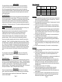
Table 2: Torque Requirements
Valve Size
Gland Nut Torque
(+ or – 10%)
in-lb (ft-lb)
Gland Plate Fastener
Torque (+ or – 10%)
in-lb (ft-lb)
Body Bolt Torque
(+ or – 10%)
in-lb (ft-lb)
1/4 96 (8) N/A 96 (8)
3/8 96 (8) N/A 96 (8)
1/2 156 (13) N/A 96 (8)
3/4 156 (13) N/A 96 (8)
1 516 (43) N/A 96 (8)
1-1/4 516 (43) N/A 156 (13)
1-1/2 516 (43) N/A 156 (13)
2 516 (43) N/A 276 (23)
2-1/2 996 (83) N/A 540 (45)
3 N/A 156 (13) 900 (75)
4 N/A 156 (13) 2400 (200)
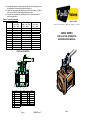
PARTS ILLUSTRATION
2
6
8
10
9
11
12
4
17
18
20
7
22
13
1
21
19
NO. NA ME NO. NA ME NO. NA ME
1HANDLE SCREW 9SEAT 16 STOP
2ADPT SCREW 10BODY SEAL 17LOCKPLATE
3STOP SCREW 11STEM PACKING18BALL
4PACKING GLAND12STEM 19 END CAP
5GLAND SCREW 13HANDLE 20SEAT HOLDER
6BODY BOLT 14HANDLE ADPT 21BODY
7NUT 15 GLAND PLATE 22 LOCK WASHER
8STEM BEARING
Page 4
I346600 Rev. C
A Division of Conbraco Industries, Inc. Matthews, NC Pageland, SC Conway, SC
82/82A SERIES
INSTALLATION, OPERATION
& MAINTENANCE MANUAL
Page 1

INSTALLATION
The Apollo 82/82A Series Ball valves are bi-directional. They may be installed in
vertical or horizontal pipe runs without regard to flow direction or stem orientation.
Note: Valves must be installed in piping systems that comply with the applicable
portions the ASME B31 standards. Special considerations must be taken with respect
to pipe line expansions and contractions and the media expansion and contractions
within the piping system.
Threaded End Valves
Pipe connection to be threaded into these valves should be accurately threaded, clean
and free of foreign material or metal shavings. PTFE pipe tape is recommended for
use as the pipe joint sealant. Two wrenches must be used when making up pipe joints
to these valves. Apply one wrench on the valve end closest to the pipe joint being
tightened and the other wrench to the pipe to prevent transmitting torque through the
valve body joint. Typical pipe make-up is 1-1/2 turns after installing the pipe hand-tight.
Solder End (Sweat In) Valves
Caution: 82/82A series valves must be partially disassembled before soldering in line.
Damage to seats and seals is likely without partial disassembly.
Begin by placing the valve in the open position and loosening the four body bolts.
Complete removal of one bolt is required. Next, remove the center section
subassembly and set aside. Protect seat and seal surfaces from damage.
Carefully, solder the end caps in line. Overheating bronze end caps can cause
permanent damage. Protect the end cap faces from damage during soldering.
Once the end caps have completely cooled to the touch, reinstall the center section
subassembly. Valves 2” and smaller are shipped with an extra set of seats. Replace
the used seats prior to reassembly. Install the body bolts and hand-tighten all four hex
nuts. Using a criss-cross pattern, in three approximately equal steps, torque the body
bolts to the value given in Table 2. Cycle the valve open and closed between each
step to assure continued smooth operation. Complete the fastener torquing sequence
with one final check going around the bolt pattern clockwise at the specified torque
level.
OPERATION
The valve handle is marked showing proper rotation direction for “ON” and “OFF”
positions. Rotation is clockwise for “OFF” (closed) and counterclockwise for “ON”
(open).
MAINTENANCE
Regular Maintenance
Normal stem packing wear can be compensated for by adjusting the packing gland nut
(1/4” thru 2-1/2” valves) or gland plate fasteners (3” & 4” valves). The handle may need
to be removed for easy access to the packing gland nut. Wrench part number H371400
is available to ease this operation. Tighten the packing gland nut or gland plate
fasteners clockwise in 1/8 turn increments until observed leakage stops. Do not exceed
the torque levels shown in Table 2. Reinstall the handle if necessary.
Major Overhaul
Due to the uncomplicated design of the 82/82A series, these valves can easily be
rebuilt. Repair kits are available and can be purchased through your local distributor.
These kits typically contain a complete set of seats and seals. Complete center
sections are also available.
Page 2
Table 1: Repair Kits
Valve Size Kit Number
(RPTFE)
Valve Size Kit Number
(RPTFE)
1/4” & 3/8” 8200201 1-1/2” 8200701
1/2” 8200301 2” 8200801
3/4” 8200401 2-1/2” 8200901
1” 8200501 3” 82A00001
1-1/4” 8200601 4” 82A00A01
Disassembly
1) After de-pressurizing the system, operate the valve fully open to fully closed to
assure there are no trapped fluids or pressure in the body cavity. Return the
valve to the open position for disassembly.
2) Begin disassembly by loosening the body bolts. Complete removal of one bolt
is required for center section removal.
3) Remove the center section from the piping system. It may be necessary to
spread the end caps slightly to overcome compressive loads imparted by the
piping system.
4) After removing the center section from the piping system, rotate the handle to
the closed position for ball and seat removal. Carefully press the spherical
surface of the ball by hand for removal of the first seat. Press in the opposite
direction to remove the other seat.
5) If ball inspection reveals scars or other damage, it is recommended that the
complete center section be replaced.
6) If no ball damage is found, continue the rebuild process by removing the
handle. The packing gland nut or gland plate, packing gland and fasteners
should also be removed.
7) Press the stem downward into the body to facilitate removal of the stem, stem
bearing and stem packing. Do not damage sealing surfaces when removing
the stem.
8) Finally, remove the stem packing. Do not scratch or scar the packing box.
Re-Assembly
1) Begin the re-assembly process by cleaning each of the component parts with
a clean towel or cloth.
2) Place the new stem bearing on the stem, and insert the stem into the valve
body stem bore. Place the flats on top of the stem perpendicular to the
centerline of the body.
3) Install the stem packing, packing gland nut, or packing gland, gland plate, and
fasteners as required. Tighten finger tight only at this time.
4) Carefully insert the ball into the body. Rotate the stem to the open position.
5) Apply a small amount of service compatible lubricant to the new seats and
install them in the valve body. Seats may be installed dry however some
assembly lubricant is desirable and acts to hold the seats in place during the
assembly process.
6) Install the body seal on valves 2-1/2” and larger.
7) Slip the body subassembly into the end caps installed in the pipeline.
Lubricate and install the body bolts and nuts finger tight at this time.
8) Cycle the valve open and closed several times to assure all components are
properly aligned.
9) Using a criss-cross pattern, in three approximately equal steps, torque the
body bolts to the value given in Table 2. Cycle the valve open and closed
between each step to assure continued smooth operation.
Page 3
-
 1
1
-
 2
2


Ask a question and I''ll find the answer in the document
Finding information in a document is now easier with AI
Related papers
-
Apollo Conbraco 82LF24501 Installation guide
-
Apollo 94ALF20601A Installation guide
-
Apollo Conbraco 7064456 Installation guide
-
Apollo Conbraco 77CLF20801 Installation guide
-
Apollo 77F20301 Installation guide
-
Apollo Conbraco 61LF60701 Installation guide
-
-
Apollo Valves 70LF10501 Installation guide
-
Apollo Conbraco 77CLF24404A Installation guide
-
Other documents
-
Apollo Saturn Series Installation, Operation and Maintenance Manual
-
KTM Series PDS (Powder Discharge System) Ball Valve IOM Owner's manual
-
Vogt Valves AAB85VV001001 Installation guide
-
 JB Ball Valves IOM_79-700 Operating instructions
-
-
Ham-Let Valves & Fittings 3000450 Installation guide
-
-
Everbilt 119-4-34-EB User manual
-
-
