Page is loading ...

Operator’s Manual
& Parts Drawings
Field Mower
Serial Number LQ450-AD1307 --
VENTRAC.COM
LQ450
Revised 02/02/20
09.10063 Rev. 06
Original Operator’s Manual

2
To the Owner
Contact Information and Product Identication
If you need to contact an authorized Ventrac dealer for information on servicing your product,
always provide the product model and serial numbers.
Please ll in the following information for future reference. See the picture(s) below to nd the
location of the identication numbers. Record them in the spaces provided.
Date of Purchase: __________________________________________________________________
Dealer: ___________________________________________________________________________
Dealer Address: ____________________________________________________________________
____________________________________________________________________
Dealer Phone Number: ______________________________________________________________
Dealer Fax Number: ________________________________________________________________
Model # (A): __________________________
Serial # (B): __________________________
Afx Part/Serial Number label here.
Venture Products Inc. reserves the right to make changes
in design or specications without obligation to make like
changes on previously manufactured products.
BB
AA
500 Venture Drive
Orrville Oh 44667
www.ventrac.com
View all manuals
Visit ventrac.com/manuals
for the latest version of this
operator’s manual.
A downloadable parts manual
is also available.

TABLE OF CONTENTS
3
INTRODUCTION PAGE 5
Product Description ................................................................................................................................ 5
Why Do I Need an Operator’s Manual? .................................................................................................5
Using Your Manual .................................................................................................................................6
Manual Glossary ....................................................................................................................................6
SAFETY PAGE 7
Safety Decals .........................................................................................................................................7
General Safety Procedures .................................................................................................................... 9
Training Required ...................................................................................................................................9
Personal Protective Equipment Requirements ......................................................................................9
Operation Safety ....................................................................................................................................9
Preventing Accidents ............................................................................................................................10
Keep Riders O ....................................................................................................................................10
Operating On Slopes ............................................................................................................................ 11
Roadway Safety ................................................................................................................................... 11
Truck Or Trailer Transport .................................................................................................................... 11
Maintenance .........................................................................................................................................12
Fuel Safety ...........................................................................................................................................12
Hydraulic Safety ...................................................................................................................................13
Cutting Unit Safety ...............................................................................................................................14
OPERATIONAL CONTROLS PAGE 15
Cutting Height Selection .......................................................................................................................15
Drive Belt Tension Spring ..................................................................................................................... 15
Primary S.D.L.A. Control Lever ............................................................................................................ 15
Weight Transfer .................................................................................................................................... 15
GENERAL OPERATION PAGE 16
Daily Inspection .................................................................................................................................... 16
Attaching ..............................................................................................................................................16
Detaching .............................................................................................................................................16
Mowing and Operating Procedure .......................................................................................................16
Transport of Mower ..............................................................................................................................17
Cutting Height Adjustment ....................................................................................................................17
SERVICE PAGE 18
Cleaning and General Maintenance.....................................................................................................18
Mower Blade Removal & Installation ...................................................................................................18
Sharpening Blades ............................................................................................................................... 18
Deck Belt Inspection ............................................................................................................................18
Tire Pressure ........................................................................................................................................ 18
Lubrication ............................................................................................................................................19
Storage .................................................................................................................................................19
Maintenance Schedule .........................................................................................................................20
Maintenance Checklist .........................................................................................................................20

TABLE OF CONTENTS
4
SPECIFICATIONS PAGE 21
Dimensions ..........................................................................................................................................21
Features ...............................................................................................................................................21
PARTS PAGE 22
Main Deck ............................................................................................................................................22
Hitch Frame, Wheel, & Axle Grass Guards .......................................................................................... 24
Spindles & Pulleys ...............................................................................................................................26
70.0108 LT Shield Kit for LQ450 (LT3000) ...........................................................................................28
70.3021 LE Shield Kit for LQ450 (LE3100 & LE3200) .........................................................................30
70.3047 LH Shield Kit for LQ450 (LH3400) .........................................................................................32
WARRANTY PAGE 34

INTRODUCTION
Introduction - 5
Product Description
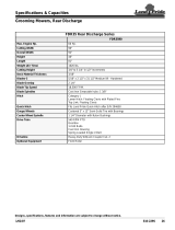
The Ventrac LQ450 eld mower is designed for the sole purpose of mowing heavy grass and small brush.
Two counter-rotating blades discharge the cut grass to the center rear. Suspended front chains allow tall
grass to be cut more eectively and reduce the potential for front discharge. Three pins provide three cut-
ting height options: 2 1/4, 3 1/2, and 4 3/4 inches (5.7, 8.9, and 12.1 cm).
A single swivel tire is located on the front center frame of the mower. This position greatly reduces tree
branch interference. Skid shoes on both sides provide anti-scalping and blade protection.
The tree shield kit can be installed for use on tree farms, vineyards, nurseries, etc. This shielding protects
both the trees and the operator. Branch lifters and power unit tire covers are standard equipment with the
tree shield kit.
Why Do I Need an Operator’s Manual?
This manual has been created to help you gain the important knowledge of what is needed to safely
operate, maintain, and service your machine. It is divided into sections for convenient reference of the
appropriate section.
You must read and understand the operator’s manual for each piece of Ventrac equipment you own. Read-
ing the operator’s manual will help you become familiar with each specic piece of equipment. Under-
standing the operator’s manual will help you, as well as others, avoid personal injury and/or damage to the
equipment. Keep this manual with the machine at all times. The manual should remain with the machine
even if it is sold. If this manual becomes damaged or unreadable, it should be replaced immediately. Con-
tact your local Ventrac dealer for a replacement.
When using a Ventrac attachment, be sure to read and follow the safety and operating instructions of both
the power unit and the attachment being used to ensure the safest operation possible.
The information in this manual provides the operator with the safest procedures to operate the machine
while getting the maximum use out of the unit. Failure to follow the safety precautions listed in this manual
may result in personal injury and/or damage to the equipment.
INTRODUCTION
Accessories
Item Description
Part Number
LT Shield Kit For LQ450 (LT3000) 70.0108
LE Shield Kit For LQ450 (LE3100 & LE3200) 70.3021
LH Shield Kit For LQ450 (LH3400) 70.3047
V
enture Products Inc. is pleased to provide you with your new
Ventrac eld mower! We hope that Ventrac equipment will
provide you with a ONE Tractor Solution.
Listed below are just some of the items that can provide you
versatility as you use your LQ450. Please visit our web site, or
contact your authorized Ventrac dealer for a complete list of
items available for your new mower.

INTRODUCTION
Introduction - 6
Using Your Manual
Throughout this manual, you will encounter special messages and symbols that identify potential safety
concerns to help you as well as others avoid personal injury or damage to the equipment.
ATTENTION
This symbol identies potential health and
safety hazards. It marks safety precautions.
Your safety and the safety of others is involved.
SYMBOL DEFINITIONS
There are three signal words that describe the level of safety concern: Danger, Warning, and Caution.
Safety should always be the #1 priority when working on or operating equipment. Accidents are more likely
to occur when proper operating procedures are not followed or inexperienced operators are involved.
Note: Right-Hand and Left-Hand orientations may be referred to at dierent places throughout this manual.
Right-Hand and Left-Hand is determined as if sitting on the power unit seat facing forward.
SIGNAL WORD DEFINITIONS
Indicates a potentially hazardous situation
which, if not avoided, could result in death or
serious injury.
Indicates an imminently hazardous situation
which, if not avoided, will result in death or
serious injury. This signal word is limited to the
most extreme cases.
Indicates a potentially hazardous situation
which, if not avoided, may result in minor or
moderate injury and/or property damage. It may
also be used to alert against unsafe practices.
Manual Glossary
Power Unit A Ventrac tractor or other Ventrac engine powered device that may be operated by itself or
with an attachment or accessory.
Attachment A piece of Ventrac equipment that requires a Power Unit for operation.
Accessory A device that attaches to a Power Unit or Attachment to extend its capabilities.
Machine Describes any “Attachment” or “Accessory” that is used in conjunction with a power unit.

SAFETY
Safety - 7
Safety Decals
The following safety decals must be maintained on your LQ450 eld mower.
Keep all safety decals legible. Remove all grease, dirt, and debris from safety decals and instructional
labels. If any decals are faded, illegible, or missing, contact your dealer promptly for replacements.
When new components are installed, be sure that current safety decals are axed to the replacement
components.
SAFETY
AA
BB
CC
DD
DD
DD
EE

SAFETY
Safety - 8
Decal Description Part Number Quantity
A Danger, Shield Missing 00.0062 1
B Warning - Moving Part Hazard 00.0101 1
C Danger, Thrown Object Hazard 00.0122 1
D Danger, Keep Hands and Feet Clear 00.0123 3
E Warning, Read Owner’s Manual 00.0217 1
AA
BB CC
DD EE

SAFETY
Safety - 9
General Safety Procedures
for Ventrac Power Units, Attachments, & Accessories
Training Required
• The owner of this machine is solely responsible for properly training the operators.
• The owner/operator is solely responsible for the operation of this
machine and prevention of accidents or injuries occurring to him/her-
self, other people, or property.
• Do not allow operation or service by children or untrained personnel.
Local regulations may restrict the age of the operator.
• Before operating this machine, read the operator’s manual and under-
stand its contents.
• If the operator of the machine cannot understand this manual, then it
is the responsibility of this machine’s owner to fully explain the material
within this manual to the operator.
• Learn and understand the use of all controls.
• Know how to stop the power unit and all attachments quickly in the event of an emergency.
Personal Protective Equipment Requirements
It is the responsibility of the owner to be sure that the operators use the proper personal protective equip-
ment while operating the machine. Required personal protective equipment includes, but is not limited to,
the following list.
• Wear a certied ear protection device to prevent loss of hearing.
• Prevent eye injury by wearing safety glasses while operating the machine.
• Closed toe shoes must be worn at all times.
• Long pants must be worn at all times.
• When operating in dusty conditions, it is recommended that a dust mask be worn.
Operation Safety
• Inspect machine before operation. Repair or replace any damaged, worn, or missing parts. Be sure
guards and shields are in proper working condition and are secured in place. Make all necessary
adjustments before operating machine.
• Some pictures in this manual may show shields or covers opened or removed in order to clearly illustrate
any instructions. Under no circumstance should the machine be operated without these devices in place.
• Alterations or modications to this machine can reduce safety and could cause damage to the machine.
Do not alter safety devices or operate with shields or covers removed.
• Before each use, verify that all controls function properly and inspect all safety devices. Do not operate
if controls or safety devices are not in proper working condition.
• Check parking brake function before operating. Repair or adjust parking brake if necessary.
• Observe and follow all safety decals.
• All controls are to be operated from the operator’s station only.
• Always wear a seat belt if the machine has a roll cage/bar installed and in upright position.
• Ensure the attachment or accessory is locked or fastened securely to the power unit before operating.
• Ensure that all bystanders are clear of the power unit and attachment before operating. Stop machine if
someone enters your work area.
• Always be alert to what is happening around you, but do not lose focus on the task you are performing.
Always look in the direction the machine is moving.
• Look behind and down before backing up to be sure of a clear path.
• If you hit an object, stop and inspect the machine. Make all necessary repairs before operating machine again.
• Stop operation immediately at any sign of equipment failure. An unusual noise can be a warning of equipment
failure or a sign that maintenance is required. Make all necessary repairs before operating machine again.

SAFETY
Safety - 10
General Safety Procedures
for Ventrac Power Units, Attachments, & Accessories
• If equipped with a high/low range feature, never shift between high and low range while on a slope.
Always move the machine to level ground and engage the parking brake before shifting range.
• Do not leave machine unattended while it is running.
• Always park the machine on level ground.
• Always shut o engine when connecting attachment drive belt to the power unit.
• Never leave the operator’s station without lowering the attachment to the ground, setting the parking
brake, shutting o the engine, and removing the ignition key. Make sure all moving parts have come to
a complete stop before dismounting.
• Never leave equipment unattended without lowering the attachment to the ground, setting the parking
brake, shutting o the engine, and removing the ignition key.
• Only operate in well-lit conditions.
• Do not operate when there is a risk of lightning.
• Never direct the discharge of any attachment in the direction of people, buildings, animals, vehicles, or
other objects of value.
• Never discharge material against a wall or obstruction. Material may ricochet back towards the operator.
• Use extra caution when approaching blind corners, shrubs, trees, or other objects that may obscure vision.
• Do not run the engine in a building without adequate ventilation.
• Do not touch the engine or the muer while the engine is running or immediately after stopping the engine.
These areas may be hot enough to cause a burn.
• Do not change the engine governor settings or over-speed the engine. Operating engine at excessive speed
may increase the hazard of personal injury.
• To reduce the hazard of re, keep the battery compartment, engine, and muer areas free of grass, leaves,
excessive grease, and other ammable materials.
Preventing Accidents
• Clear working area of objects that might be hit or thrown from machine.
• Keep people and pets out of working area.
• Know the work area well before operation. Do not operate where traction or
stability is questionable.
• Reduce speed when you are operating over rough ground.
• Equipment can cause serious injury and/or death when improperly used.
Before operating, know and understand
the operation and safety of the power
unit and the attachment being used.
• Do not operate machine if you are not in good physical and
mental health, if you will be distracted by personal devices, or are
under the inuence of any substance which might impair deci-
sion, dexterity, or judgment.
• Children are attracted to machine activity. Be aware of children
and do not allow them in the working area. Turn o the machine if
a child enters the work area.
Keep Riders O
• Only allow the operator on the power unit. Keep riders o.
• Never allow riders on any attachment or accessory.
Operation Safety (continued)

SAFETY
Safety - 11
General Safety Procedures
for Ventrac Power Units, Attachments, & Accessories
Operating On Slopes
• Slopes can cause loss-of-control and
tip-over accidents, which can result in
severe injury or death. Be familiar with the
emergency parking brake, along with the
power unit controls and their functions.
• If power unit is equipped with a fold down
roll bar, it must be locked in the upright
position when operating on any slope.
• Use low range (if equipped) when operating
on slopes greater than 15 degrees.
• Do not stop or start suddenly when operating on slopes.
• Never shift between high and low range while on a slope. Always move the power unit to level ground
and engage the parking brake before shifting range or placing the power unit in neutral.
• Variables such as wet surface and loose ground will reduce the degree of safety. Do not drive where
machine could lose traction or tip over.
• Keep alert for hidden hazards in the terrain.
• Stay away from drop-os, ditches, and embankments.
• Sharp turns should be avoided when operating on slopes.
• Pulling loads on hills decreases safety. It is the responsibility of the owner/operator to determine loads
that can safely be controlled on slopes.
• Transport machine with attachment lowered or close to the ground to improve stability.
• While operating on slopes, drive in an up and down direction when possible. If turning is necessary
while driving across slopes, reduce speed and turn slowly in the downhill direction.
• Assure a sucient supply of fuel for continuous operation. A minimum of one-half tank of fuel is recommended.
Roadway Safety
• Operate with safety lights when operating on or near roadways.
• Obey all state and local laws concerning operation on roadways.
• Slow down and be careful of trac when operating near or crossing roadways. Stop before crossing
roads or sidewalks. Use care when approaching areas or objects that may obscure vision.
• If there is doubt of safety conditions, discontinue machine operation until a time when
operation can be performed safely.
• When operating near or on roadways, have a Slow Moving Vehicle Emblem clearly
displayed.
Truck Or Trailer Transport
• Use care when loading or unloading machine into a truck or trailer.
• Use full width ramps for loading machine into a truck or trailer.
• The parking brake is not sucient to lock the machine during transport. Always secure the power unit
and/or attachment to the transporting vehicle securely using straps, chains, cable, or ropes. Both front
and rear straps should be directed down and outward from the machine.
• Shut o fuel supply to power unit during transport on truck or trailer.
• If equipped, turn the battery disconnect switch to the O position to shut o electrical power.

SAFETY
Safety - 12
General Safety Procedures
for Ventrac Power Units, Attachments, & Accessories
Maintenance
• Keep all safety decals legible. Remove all grease dirt, and debris from safety decals and instructional labels.
• If any decals are faded, illegible, or missing, contact your dealer promptly for replacements.
• When new components are installed, be sure that current safety decals are axed to the replacement
components.
• If any component requires replacement, use only original Ventrac replacement parts.
• Always turn the battery disconnect to the O position or disconnect the battery before performing any
repairs. Disconnect the negative terminal rst and the positive terminal last. Reconnect the positive
terminal rst and the negative terminal last.
• Keep all bolts, nuts, screws, and other fasteners properly tightened.
• Always lower the attachment to the ground, engage parking brake, shut o engine, and remove the
ignition key. Make sure all moving parts have come to a complete stop before cleaning, inspection,
adjusting or repairing.
• If the power unit, attachment, or accessory requires repairs or adjustments not instructed in the operator’s
manual, the power unit, attachment, or accessory must be taken to an authorized Ventrac dealer for service.
• Never perform maintenance on the power unit and/or attachment if someone is in the operator’s station.
• Always use protective glasses when handling the battery.
• Check all fuel lines for tightness and wear on a regular basis. Tighten or repair them as needed.
• To reduce the hazard of re, keep the battery compartment, engine, and muer areas free of grass,
leaves, and excessive grease.
• Do not touch the engine, the muer, or other exhaust components while the engine is running or imme-
diately after stopping the engine. These areas may be hot enough to cause a burn.
• Allow the engine to cool before storing and do not store near an open ame.
• Do not change the engine governor settings or over-speed the engine. Operating engine at excessive
speed may increase the hazard of personal injury.
• Springs may contain stored energy. Use caution when disengaging or removing springs and/or spring
loaded components.
• An obstruction or blockage in a drive system or moving/rotating parts may cause a buildup of stored
energy. When the obstruction or blockage is removed, the drive system or moving/rotating parts may
move suddenly. Do not attempt to remove an obstruction or blockage with your hands. Keep hands,
feet, and clothing away from all power-driven parts.
• Dispose of all uids in accordance with local laws.
Fuel Safety
• To avoid personal injury or property damage, use extreme care in handling gasoline. Gaso-
line is extremely ammable and the vapors are explosive.
• Do not refuel machine while smoking or at a location near ames or sparks.
• Always refuel the machine outdoors.
• Do not store machine or fuel container indoors where fumes or fuel can reach an open
ame, spark, or pilot light.
• Only store fuel in an approved container. Keep out of reach of children.
• Never ll containers inside a vehicle or on a truck or trailer bed with a plastic liner. Always place containers
on the ground away from your vehicle before lling.
• Remove machine from the truck or trailer and refuel it on the ground. If this is not possible, refuel the
machine using a portable container, rather than from a fuel dispenser nozzle.
• Never remove fuel cap or add fuel with the engine running. Allow engine to cool before refueling.
• Never remove fuel cap while on a slope. Only remove when parked on a level surface.
• Replace all fuel tank and container caps securely.

SAFETY
Safety - 13
General Safety Procedures
for Ventrac Power Units, Attachments, & Accessories
• Do not overll fuel tank. Only ll to bottom of fuel neck, do not ll fuel neck full. Overlling of fuel tank could
result in engine ooding, fuel leakage from the tank, and/or damage to the emissions control system.
• If fuel is spilled, do not attempt to start the engine. Move the power unit away from the fuel spill and
avoid creating any source of ignition until fuel vapors have dissipated.
• If the fuel tank must be drained, it should be drained outdoors into an approved container.
• Dispose of all uids in accordance with local laws.
• Check all fuel lines for tightness and wear on a regular basis. Tighten or repair them as needed.
• The fuel system is equipped with a shut-o valve. Shut o the fuel when transporting the machine to
and from the job, when parking the machine indoors, or when servicing the fuel system.
Hydraulic Safety
• Make sure all hydraulic connections are tight and all hydraulic hoses and tubes are in good condition.
Repair any leaks and replace any damaged or deteriorated hoses or tubes before starting the machine.
• Hydraulic leaks can occur under high pressure. Hydraulic leaks require special care and attention.
• Use a piece of cardboard and a magnifying glass to locate sus-
pected hydraulic leaks.
• Keep body and hands away from pinhole leaks
or nozzles that eject high pressure hydraulic uid.
Hydraulic uid escaping under high pressure can
penetrate the skin causing serious injury, leading to
severe complications and/or secondary infections
if left untreated. If hydraulic uid is injected into the
skin, seek immediate medical attention no matter
how minor the injury appears.
• Hydraulic system may contain stored energy. Before performing maintenance or repairs on the hydraulic
system, remove attachments, engage parking brake, disengage weight transfer system (if equipped),
shut o engine, and remove ignition key. To relieve pressure on the auxiliary hydraulic system, shut o the
power unit engine and move the hydraulic control lever left and right before disconnecting the auxiliary
hydraulic quick couplers.
• Dispose of all uids in accordance with local laws.
Fuel Safety (continued)

SAFETY
Safety - 14
Cutting Unit Safety
• Rotating Blades: Contact with the rotating mower blades or other moving parts may cause
personal injury. Keep hands and feet away.
• Rotation of one blade may cause another blade to rotate.
• Thrown Object Hazard: Do not point discharge toward people, animals, or buildings when
operating. Never operate with the deectors removed.
• When not mowing, always shut o the PTO to stop the mower blades.
• Never raise the mower deck with the blades running.
LQ450 Safety Procedures

Operation - 15
Cutting Height Selection
The cutting height of the LQ450 is controlled by
three pins (one at the front of the deck and two at
the rear of the deck).
AA
AA
AA
BB
BB
BB
CC
CC
CC
Placing the pins in position A will result in a cutting
height of 2-1/4” (5.7 cm).
Placing the pins in position B will result in a cutting
height of 3-1/2” (8.9 cm).
Placing the pins in position C will result in a cutting
height of 4-3/4” (12.1 cm).
Drive Belt Tension Spring
AA
AA
BB
BB
The drive belt tension spring places tension on the
LQ450 drive belt. Hook both arms (A) of the tension
spring over the tension spring bolts (B).
Primary S.D.L.A. Control Lever
Pull the lever to the left to raise the power unit front
hitch and LQ450 eld mower. Push the lever to the
right to lower the power unit front hitch and LQ450
eld mower. The control lever must be in the oat
(detent) position during operation of the mower.
Weight Transfer
Terrain and ground conditions may aect the appro-
priate setting for the power unit’s weight transfer
system (if equipped). In most cases, the weight
transfer system should be set from 1/2 to 3/4 of
maximum capacity.
*
*
OPERATIONAL CONTROLS
* Refer to power unit operator’s manual for operation of power
unit controls.

Operation - 16
GENERAL OPERATION
Daily Inspection
1.
Always set the parking brake, shut o the power
unit engine, remove the ignition key, and ensure
all moving parts have stopped before checking
mower deck or blade condition, or attempting
any repair or adjustment.
Park the power unit and mower deck on a level
surface, with the engine shut o and all uids cold.
2. Perform a visual inspection of the power unit and
mower deck. Look for loose or missing hard-
ware, damaged components, or signs of wear.
Inspect hydraulic hoses, hydraulic ttings, and
fuel lines to ensure tight, leak free connections.
3. Refer to the power unit operator’s manual.
Check the power unit’s engine oil, hydraulic oil,
cooling system, tire pressure, and fuel level. Add
uid or service system as required.
4. Inspect the drive belts and mower blades. Belts
should be in good condition. Blades should be
sharp and securely fastened. Service as required.
5. Refer to the power unit operator’s manual. Test
the power unit’s operator safety interlock system.
Attaching
1. Drive the power unit slowly forward into the hitch
arms of the eld mower. Align the lift arms of the
power unit with the eld mower hitch arms by
raising or lowering the front hitch and complete
the engagement.
2. Once completely engaged, close the front hitch
locking lever.*
3. Engage the parking brake* and shut o the engine.
4. Place the attachment belt onto the PTO drive
pulley on the power unit. Ensure the belt is prop-
erly seated in each pulley.
5. Remove the top deck covers and engage the
drive belt tension spring.
6. Reinstall the top deck covers.
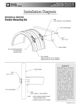
7. If the power unit is equipped with a shield kit,
install the limb pickup rods to the rod mounts on
the power unit.
Detaching
1. Park the power unit on a level surface and set
the parking brake.*
2. Lower the eld mower to the ground. NOTE: set-
ting the back of the eld mower on blocks will raise
the hitch arms and allow for easier reattachment.
3. Shut o power unit engine.
4. Remove the limb pickup rods from the rod
mounts on the power unit (if equipped).
5. Remove the top deck covers and disengage the
PTO tension spring.
6. Remove the attachment belt from the PTO drive
pulley of the power unit.
7. Reinstall the top deck covers.
8. Disengage the front hitch locking lever.*
9. Restart the power unit and slowly back away
from the mower. A side to side movement of the
steering wheel may aid disengagement.
If the power unit is equipped with a shield kit, the
shields can remain on the power unit, although
some attachments may require the removal of the
front tire shields.
Mowing and Operating Procedure
Before operation, perform daily inspection and
conrm that the cutting height is set properly. Set the
power unit’s weight transfer system* (if equipped) to
the desired setting.
With the power unit engine running between 2,000
and 2,500 RPM, engage the PTO switch. Adjust the
throttle to the desired engine RPM.
Lower the mower deck to the ground and place
the power unit’s primary S.D.L.A. control lever in
the oat position by pushing it to the right until the
detent engages. The lever will stay in this position
until intentionally removed.
Begin forward motion in the desired path of mowing.
Avoid obstacles, removing debris as necessary.
Lift the mower deck when the edge of the mowing
area is reached. Turn the power unit and mower
around and align for the next pass.
Always shut o the engine, remove the ignition
key, and set the parking brake before checking
mower deck or blade condition, or attempting
any repair or adjustment.
Blades should be kept in good condition. Sharp
blades will increase eciency and improve the
quality of cut.
Mowing in wet conditions may result in a build up of
clippings under the deck. Periodic checking should be
done by the operator to determine if the deck should
be cleaned. The deck should also be checked any-
time mowing performance seems to be reduced.
* Refer to power unit operator’s manual for operation of power
unit controls.

GENERAL OPERATION
Operation - 17
Transport of Mower
Transport the mower deck with the power unit front
hitch and mower fully raised to reduce wear of the
equipment. Travel slowly when transporting over
undulating and rough surfaces to maintain control of
power unit and to reduce the shock to the power unit
and mower deck. Always disengage the power unit
PTO before transporting the mower.
Cutting Height Adjustment
1.
Always shut o the engine, remove the ignition
key, and set the parking brake before checking
mower deck or blade condition, or attempting
any repair or adjustment.
Park the power unit and eld mower on a
smooth, level surface and lower the mower deck
to the ground.
2. Set the parking brake, shut o the engine, and
remove the ignition key.
3. Remove the top deck covers and release the
drive belt tension spring.
4. Pull the pin from the front of the deck and manu-
ally lift or lower the front of the deck to the pre-
ferred cutting height.
5. Place the two pins in the rear of the deck into
the corresponding holes of the height selection
plates. (If the front pin is in position A, the rear
pins must also be in position A.)
6. Ensure the hairpins are securely installed on the
height selection pins.
7. Engage the drive belt tension spring and reinstall
the top deck covers.

Service - 18
Cleaning and General Maintenance
For best results, and to maintain the nish of the
mower, clean or wash the mower to remove accu-
mulated clippings, leaves, and dirt when the job is
nished.
If washing the deck, do not spray directly into bearings
or seals. After washing, it is important to run the mower
so that water does not reside on seals of bearings for
the drive system. When washing is complete, activate
the PTO for 30 seconds to remove any standing water.
Mower Blade Removal & Installation
1.
Mower blades may be sharp. Always wear
safety glasses, leather gloves, and a long
sleeve shirt when working with mower blades.
Use a hoist to lift the deck up and secure in a
position that provides easy access to the under-
side of the deck.
2. Place a short piece of 2 x 4 wood between the
end of the blade and an appropriate structural
part of the underside of the deck to prevent the
blade from rotating.
3. Loosen the left blade bolt counterclockwise and
remove the blade for sharpening or replacement.
Loosen the right blade bolt clockwise and remove
the blade for sharpening or replacement.
NOTE: the mower blades are bidirectional.
Switching the blades from one spindle to the
other will use the opposite edge of the blade.
When the edges are worn, remove the blades
and sharpen both sides of the blade.
4. When installing a blade, the wood block must be
placed on the opposite side to prevent rotation
for tightening the blade bolt.
5. Tighten the blade bolt to 75-80 ft. lbs.
Sharpening Blades
Blades should be sharpened and balanced by a pro-
fessional. Maintain balance, same bevel, and length
of sharpened surface.
Deck Belt Inspection
Inspecting the drive belt of the mower can prevent
sudden belt failure by nding problems before they
cause a belt to break. Typical wear on a drive belt
may result in the conditions shown in the diagram.
If any of these conditions occur, the drive belt will
require replacement.
Deck Belt Replacement
1. Detach the mower deck from the power unit.
2. Remove the top deck covers.
3. Remove the old deck belt.
4. Install the new deck belt. Place belt into the pul-
ley system according to the belt diagram located
on the underside of the top deck cover.
5. Ensure the belt is engaged in the groove of each
spindle pulley and around each of the idler pulleys.
Tire Pressure
The tire pressure should be maintained at 18-20 psi.
SERVICE
Always set the parking brake, shut o power
unit engine, remove the ignition key, and ensure
all moving parts have come to a complete stop
before inspecting components or attempting any
repair or adjustment.
Attention
If any component requires replacement, use only
original Ventrac replacement parts.

SERVICE
Service - 19
Lubrication
Lubrication is required at the following locations using
a lithium complex NLGI #2 grease. Refer to the main-
tenance schedule for service intervals.
Storage
Preparing the Mower for Storage
1. Clean the mower deck and frame.
2. Inspect for loose or missing hardware, damaged
components, or signs of wear. Repair or replace
any damaged or worn components
3. Inspect belts, spindles, and blades. Repair or
replace any damaged or worn components
4. Apply grease to all grease points.
5. Wipe o all excess grease or oil.
Removing the Mower from Storage
1. Clean the mower to remove any accumulated
dust or debris.
2. Inspect the mower as instructed in the daily
inspection section of this manual.
3. Test the mower to ensure all components are
working properly.

SERVICE
Service - 20
Maintenance Schedule
LQ450
Maintenance Schedule
# o
f
L
o
c
a
t
i
o
n
s
#
o
f
P
u
mp
s
A
S
N
E
E
D
E
D
D
a
i
l
y
A
t
5
0
H
o
u
r
s
A
t
1
0
0 H
o
u
r
s
A
t
1
5
0 H
o
u
r
s
A
t
2
0
0 H
o
u
r
s
A
t
2
5
0 H
o
u
r
s
A
t
3
0
0 H
o
u
r
s
A
t
3
5
0 H
o
u
r
s
A
t
4
0
0 H
o
u
r
s
A
t
4
5
0 H
o
u
r
s
A
t
5
0
0 H
o
u
r
s
A
t
5
5
0 H
o
u
r
s
A
t
6
0
0 H
o
u
r
s
A
t
6
5
0 H
o
u
r
s
A
t
7
0
0 H
o
u
r
s
A
t
7
5
0 H
o
u
r
s
A
t
8
0
0 H
o
u
r
s
A
t
8
5
0 H
o
u
r
s
A
t
9
0
0 H
o
u
r
s
A
t
9
5
0 H
o
u
r
s
A
t
1
0
0
0 H
o
u
r
s
Y
e
a
r
l
y
Grease & Lubrication: See Lubrication Section
Caster Wheel Pivot
11
9
9
9
9
9
9
9
9
9
9
9
9
9
9
9
9
9
9
9
9
9
9
9
9
9
9
9
9
9
9
9
9
9
9
9
9
9
9
9
9
Wheel Axle Bearing
1^
** 9
9
9
9
9
9
9
9
9
9
9
9
9
9
9
9
9
9
9
9
9
9
9
9
9
9
9
9
9
9
9
9
9
9
9
9
9
9
9
9
Spindle
23
9
9
9
9
9
9
9
9
9
9
9
9
9
9
9
9
9
9
9
9
9
9
9
9
9
9
9
9
9
9
9
9
9
9
9
9
9
9
9
9
9
9
9
9
9
9
9
9
^ Grease Until Fresh Grease is visible
Grease & Lubrication: See Lubrication Section
Inspection
** Operation in severe conditions may require more frequent service intervals.
Inspect for Loose, Missing, or Worn
Components.
Inspect Belts, Pulleys, Blades, and Blade
Retaining Bolts
Check Tire Pressure
Check Safety Decals
Maintenance Checklist
LQ450
Maintenance Checklist
# o
f
L
o
c
a
t
i
o
n
s
#
o
f
P
u
mp
s
A
S
N
E
E
D
E
D
D
a
i
l
y
A
t
5
0
H
o
u
r
s
A
t
1
0
0 H
o
u
r
s
A
t
1
5
0 H
o
u
r
s
A
t
2
0
0 H
o
u
r
s
A
t
2
5
0 H
o
u
r
s
A
t
3
0
0 H
o
u
r
s
A
t
3
5
0 H
o
u
r
s
A
t
4
0
0 H
o
u
r
s
A
t
4
5
0 H
o
u
r
s
A
t
5
0
0 H
o
u
r
s
A
t
5
5
0 H
o
u
r
s
A
t
6
0
0 H
o
u
r
s
A
t
6
5
0 H
o
u
r
s
A
t
7
0
0 H
o
u
r
s
A
t
7
5
0 H
o
u
r
s
A
t
8
0
0 H
o
u
r
s
A
t
8
5
0 H
o
u
r
s
A
t
9
0
0 H
o
u
r
s
A
t
9
5
0 H
o
u
r
s
A
t
1
0
0
0 H
o
u
r
s
Y
e
a
r
l
y
Grease & Lubrication: See Lubrication Section
Wheel Swivel Bearing
11
Wheel Axle Bearing
1^
**
Spindle
23
Grease & Lubrication: See Lubrication Section
Inspection
^ Grease Until Fresh Grease is visible
Inspect for Loose, Missing, or Worn
Components.
Inspect Belts, Pulleys, Blades, and Blade
Retaining Bolts
Check Tire Pressure
Check Safety Decals
** Operation in severe conditions may require more frequent service intervals.
/