Messoa SPD983 User manual
- Category
- Security cameras
- Type
- User manual
This manual is also suitable for

User
Manual
201607 982 983 A2
Speed Dome Network Camera
SPD982
SPD983

2
Table of Contents
1 Product Overview 4
1.1 Physical Characteristics 4
2 Installation 6
2.1 Package Content 6
2.2 Installation 6
2.2.1 Checking Appearance 6
2.2.2 Disassembling the Camera 7
2.2.3 Inserting Micro SD Card 8
2.2.4 Installing Desiccant 9
2.2.5 Assembling Camera 9
2.2.6 Connecting Wires 10
2.2.7 Connecting Safety Cord 11
2.2.8 Before Powering Camera 11
3 Connection 12
3.1 Network Topology 12
3.2 System Requirements 12
3.3 Connecting Process 13
3.3.1 Default IP address 13
3.3.2 Connecting from a computer & Viewing Preparation 13
3.4 IP Finder 17
4 Administration and Conguration 18
4.1 Live View 18
4.2 Conguration 20
4.2.1 PTZ Control 20
4.2.2 Information 22
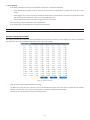
4.2.3 Image Parameters 22
4.2.4 Network Settings 30
4.2.5 Account Management 37
4.2.6 Event Settings 38
4.2.7 Recording Settings 41
4.2.8 System Settings 43

1
4.2.9 Event Log 45
4.2.10 PTZ Settings 46
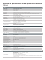
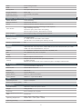
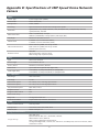
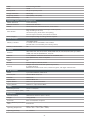
Appendix A: Specications of 3MP Speed Dome Network Camera 50
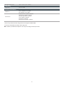
Appendix B: Specications of 3MP Speed Dome Network Camera 53

2
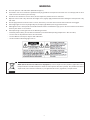
WARNING
•
This unit operates at AC 24V/ PoE+ (IEEE 802.3at type 2).
•
Installation and service should be performed only by qualied and experienced technicians and comply with all local
codes and rules to maintain your warranty.
•
To reduce the risk of re or electric shock, do not expose the product to rain or moisture.
•
Wipe the camera with a dry soft cloth. For tough stains, slightly apply with diluted neutral detergent and wipe with a dry
soft cloth.
•
Do not apply benzene or thinner to the camera, which may cause the surface of unit to be melted or lens fogged.
•
Avoid aligning the lens to very bright objects (example, light xtures) for long periods of time.
•
Although this unit is waterproof and suitable for both indoor and outdoor usages, please do not sink the unit into water.
Contact your dealer in case of sunk.
•
Avoid operating or storing the unit in the following locations:
• Extremely humid, dusty, or hot/cold environments (recommended operating temperature: -40°C to +50°C)
• Close to sources of powerful radio or TV transmitters
• Close to uorescent lamps or objects with reections
• Under unstable or ickering light sources
WEEE (Waste Electrical and Electronic Equipment). Correct disposal of this product (applicable in the
European Union and other European countries with separate collection systems). This product should be
disposed of, at the end of its useful life, as per applicable local laws, regulations, and procedures.

3
FCC Compliance Statement
Information to the user: This unit has been tested and found to comply with the limits for a Class B
digital device pursuant to Part 15 of the FCC Rules. Operation is subject to the following two conditions:
(1) this device may not cause harmful interference, and (2) this device must accept any interference
received, including interference that may cause undesired operation. These limits are designed to provide
reasonable protection against harmful interference in a residential installation. This unit generates, uses, and can radiate
radio frequency energy and, if not installed and used in accordance with the manual, may cause harmful interference to radio
communications. However, there is no guarantee that interference will not occur in a particular installation.
If this unit does cause harmful interference to radio or television reception, which can be determined by turning the unit o
and on, the user is encouraged to try to correct the interference by one or more of the following measures:
●
Reorient or relocate the receiving antenna.
●
Increase the separation between the unit and receiver.
●
Connect the unit to an outlet on a circuit dierent from that to which the receiver is connected.
●
Consult the dealer or an experienced radio/TV technician for help.
CE Statement
Operation is subject to the following two conditions: (1) this device may not cause harmful interference,
and (2) this device must accept any interference received, including interference that may cause undesired
operation. The manufacturer declares that the unit supplied with this guide is compliant with the essential
protection requirements of EMC directive and General Product Safety Directive GPSD conforming to
requirements of standards EN55022 for emission, EN 55024 for immunity, EN 300 and EN 328 for WIFI.
Caution
Changes or modications not expressly approved by the party responsible for compliance could void the
user’s authority to operate the unit.

4
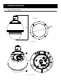
1 Product Overview
1.1 Physical Characteristics
305.1
209.28
Unit: mm
Figure 1 - 1: Physical Dimension
2
1
3
4
8
5
6
7
9
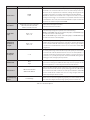
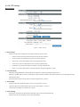
Figure 1 - 2: Pictorial Index

5
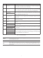
No Interface Description
1 Top Cover
The bubble-like top cover acts like an upper protection for camera body. By
loosening the 4 anti-drop screws embedded, user can further install Micro SD
card and desiccant onto the internal camera body.
2 Rear Cap
The rear cap covers the internal interface panel where user can, after loosening
the 2 screws, freely connect required cables with corresponding ports when
necessary. Also, the safety cord screw is attached here for installing demand.
3
AC 24V Ports
Connect to an applicable AC 24V power supply. Note that NC (No Connection)
port is without function but for foolproof identication. Avoid utilizing AC 24V
power supply option when PoE+ is in use.
NC
4 RJ-45 PoE+ Port
Cable this port to a standard network device, via Ethernet cable, for internet
connection or to a PoE+ compatible device for both power supply and internet
connection.
5 Default
Press and hold the button by a pin or sharp object for 6 seconds to restore to the
default camera settings.
6 Reset
Press and hold the button by a pin or sharp object for 1 second to reboot the
camera.
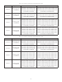
7
Audio IN
Connect to an auxiliary microphone that is able to receive surrounding sound and
transmit to camera.
Audio GND
8
COM (Alarm Out COM)
Connect to external device that is activated by alarm event signal from camera.
Connect to either NC or NO port is based on the connected device in applied
environment.
NC (Normally Closed)
NO (Normally Open)
9
GND (Alarm In GND)
Connect to multiple external devices (up to 4 devices at maximum) that can
detect and trigger alarm input signal to camera. GND port is basically shared by
the connected multiple alarm input devices.
1 (Alarm In 1)
2 (Alarm In 2)
3 (Alarm In 3)
4 (Alarm In 4)
Table 1 - 1: Pictorial Index Denition
Caution
Never connect more than one type of power supply (PoE+ (IEEE 802.3at) and AC 24V) at the same time
to avoid damage to the camera.
Note
Power supply terminal/adaptor for IO connectors and field wiring should comply with the Class 2
Circuit standard for ensuring safe from electrical fires and providing acceptable protection against
electrical shock.

6
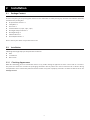
2 Installation
2.1 Package Content
2.2 Installation
Check if everything in the packing box matches to the order form and the packing slip. All items listed below should be
included in the packing box.
•
IP Speed Dome Camera * 1
•
Safety Wire * 1
•
Desiccant * 1
•
Terminal Block * 3 (8-pin, 3-pin, 2-pin)
•
Rain-Tight Compression Kit * 1
•
Rain-Tight Plugs * 3
•
T20 Torx Wrench * 1
•
Printed Quick Guide * 1
Please contact your dealer if any of the items is lost.
Following tools might help you complete the installation:
•
Drills
•
Screwdrivers
•
Wire cutters
2.2.1 Checking Appearance
When rst unboxing, please check whether if there is any visible damage to appearance of the camera and its accessories.
The protective materials used for the packaging should be able to protect the camera from most of accidents during
transportation. Please remove the protective materials when every item is properly checked in accordance with the list in “2.1
Package Content”.

7
2.2.2 Disassembling the Camera
Please refer to the steps with gures below for correct disassembling order.
1. Loosen the 4 top cover screws and detach the top cover away from the camera body.
Top Cover Screws * 4
Figure 2 - 1: Disassembling the Camera
2. Remove the protective materials that cover the lens module for embracive safety on delivery.
Protective Materials
Figure 2 - 2: Protective Materials Removing

8
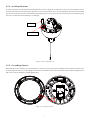
2.2.3 Inserting Micro SD Card
The speed dome camera is equipped with micro SD card slot for local recording les storage. Please follow the steps below
for the appropriate procedure of card installation.
1. Loosen the 2 lens cover screws and detach the cover away from the camera body.
2. Insert a micro SD card into the card slot indicated red within the figure below followed by turning the lever in
horizontal manner to lock the inserted card securely.
3. Restore the lens cover back to the camera body with fastening the 2 screws.
Micro SD Card Slot
Figure 2 - 3: Micro SD Card Insertion

9
2.2.4 Installing Desiccant
In order to prevent condensation from forming within the camera body, the included desiccant pack is provided for user to
manually install prior to commencing to operate the camera. First hold the desiccant pack upright with one hand and unfold
the desiccant slot with the other hand followed by putting the desiccant vertically into the slot in place. The properly held
desiccant can oer the required function accordingly.
Desiccant Slot
Desiccant
Figure 2 - 4: Desiccant Installation
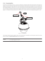
2.2.5 Assembling Camera
After both desiccant and Micro SD card installations, connect the lanyard that goes along with camera body to the top cover
via fastening with the exact screw highlighted red below. Assemble the top cover back to the camera body and tighten the 4
top cover screws to complete assembling procedure.
Figure 2 - 5: Lanyard Connection

10
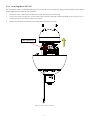
2.2.6 Connecting Wires
To full the waterproof functionality, it is necessary to utilize the included rain-tight compression kit while connecting wires
with the camera. First thread the required Ethernet wire through the compression cap and compression core in proper order
followed by threading the cable into the rear cap to connect with the corresponding port/interface on the rear panel. The 4
holes embedded within the compression core are spare for multiple wires thread and need to be blocked out via plugs when
not in use. Finally, assemble the compression kit together and rotate the compression cap clockwise to compress the kit
tightly in case of liquid leak. After that, be sure to assemble the rear cap back to the camera body by fastening the 2 screws.
Compression Cap
Compression Core
Plugs
Figure 2 - 6: Connecting Wires
For the details of ports/interfaces (power, audio, alarm, internet) that correspond to connecting wires, please refer to the
previous chapter “1.1 Physical Characteristics” for more elaborations.
Caution
Never connect more than one type of power supply (PoE+ (IEEE 802.3at) and AC 24V) at the same time
in case of damage to the camera.

11
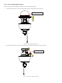
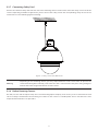
2.2.7 Connecting Safety Cord
Connect the attached safety cord with one end to the mounting surface and the other end to the safety-cord screw of the
camera. Depending on different applications, please connect the safety cord to the corresponding safety-cord screw on
varied surfaces as the following gures illustrating.
Figure 2 - 7: Safety-cord screw for ush mount
Warning
Depending on the mounting surface, you may require different screws and anchors. To prevent the
camera from falling o accidentally, ensure that the cord is connected to a rm place strong enough to
withstand the total weight of the whole set of the camera.
2.2.8 Before Powering Camera
Use soft, lint -free cloth to wipe the top cover and remove ngerprints. Properly check if every screw is well fastened and if
camera is rmly installed within the mounting area. Power on the camera via suitable power source and refer to the later
chapter for detailed web access procedure.

12
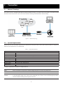
3.1 Network Topology
The camera, which is equipped with Ethernet RJ-45 network interface, can deliver live view image in real time via both
Internet and Intranet manners. Please refer to the skeleton drawings shown below for understanding.
Figure 3 - 1: Network Topology
3 Connection
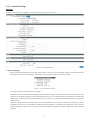
Below table lists the minimum requirement to implement and operate the camera. No hardware/software component
inferior to the requirements is recommended.
Table 3 - 1: System Requirements
System Hardware
CPU Intel Pentium 4 2.4GHz or equivalent
RAM 1 GB or above
Display NVIDIA GeForce 6 Series or ATI Mobility Radeon 9500
System Software
Operating System Microsoft Windows Vista, Windows 7 or above
Browser Microsoft Internet Explorer 9 or 10
Unit
Power Supply AC 24V / PoE+ (IEEE 802.3at)
Networking
Wired* 10/100 Mb Ethernet (CAT.5e cable recommended)
*a switch is required for surveillance on multiple cameras.
Note All the installation and operations should comply with your local electricity safety rules.
Caution
To avoid damage to the camera, never connect more than one type of power supply (PoE+ (IEEE 802.3at)
or AC 24V power plug) at the same time. If using PoE+, this camera is to be connecting only to PoE+
networks without routing to heterogeneous devices.
3.2 System Requirements

13
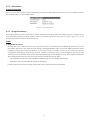
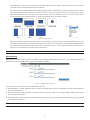
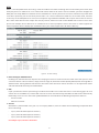
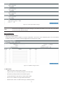
3.3.1 Default IP address
Since this is a network-based unit, an IP address must be assigned at the very first. The unit’s default IP address is
192.168.1.30 and sub mask is 255.255.255.0. However, if you have a DHCP server in your network, the unit would obtain
an IP address automatically from the DHCP server so that you don’t need to change the camera’s IP address. But be sure to
enable DHCP in "Network Settings".
3.3.2 Connecting from a computer & Viewing Preparation
Connecting from a computer
1. Make sure the unit and your computer are in the same subnet.
2. Check whether if the networking available between the unit and the computer by executing ping the default IP address.
To do this, simply start a command prompt (Windows: from the Start Menu, select Program. Then select Accessories
and choose Command Prompt.), and type “Ping 192.168.1.30”. If the message “Reply from…” appears, it means the
connection is available.
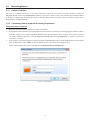
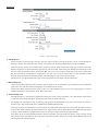
3. Start a browser e.g. Internet Explorer and enter IP address: 192.168.1.30. A login window should pop up. In the window,
enter the default user name: admin, password: 1234 and select a user interface language to log in.
Further administration on the unit can be found in “4. Administration and Conguration".
Figure 3 - 2: Login Window
3.3 Connecting Process

14
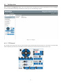
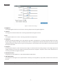
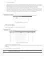
Viewing Preparation
Images of the unit can be viewed through Microsoft Internet Explorer 8 or above. Before viewing, follow these steps to
enable the display.
1. Enable Cookies as instructions below
In Internet Explorer, click Internet Options on the Tools menu.
On the Privacy tab, move the settings slider to Low or Accept All Cookies.
Click OK.
2. When a proxy server is used, click Internet Options on the Tools menus of Internet Explorer, select Connect tab, click
LAN button, and set proxy server.
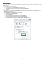
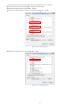
3. Change Security in Internet options as instructions below
On tool menu, click Internet Option.
Press the Security tab.
If the camera operates inside of the intranet, click the Intranet icon.
If the camera operates outside of the intranet, click the Internet icon.
Click Custom Level. This will open the Security Settings – Internet Zone screen.
Figure 3 - 3: Security Settings 1/4

15
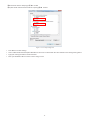
Scroll down to the ActiveX controls and plug-ins radio buttons and set as follows:
【
Download signed ActiveX controls
】
Prompt (recommended)
【
Download unsigned ActiveX controls
】
Prompt
【
Initialize and script ActiveX not marked as safe for scripting
】
Prompt
Figure 3 - 4: Security Settings 2/4
【
Automatic prompting for ActiveX controls
】
Enable
Figure 3 - 5: Security Settings 3/4

16
【
Run ActiveX controls and plug-ins
】
Enable
【
Script ActiveX controls marked safe for scripting*
】
Enable
Figure 3 - 6: Security Settings 4/4
Press OK to save the settings.
Close all Microsoft Internet Explorer Windows and restart a new window. This will allow the new settings taking eect.
Type your setting IP address into the browser.
Then you should be able to see the camera image screen.

17
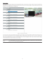
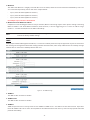
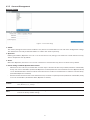
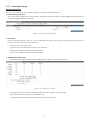
IP Finder is a utility program that helps users to locate the unit in local area network that computer is connected to. Please
note that IP Finder works only in Microsoft Windows XP, Microsoft Windows Vista, and Microsoft Windows 7 or above. Steps to
get the utility program running are listed below.
1. Download IP Finder from MESSOA Website to the computer.
2. Double click on IPFinder.exe in the IP Finder folder, and the IP Finder window should pop out.
3. The window would list information of units in operation at present. Press FIND CAMERA to nd more units.
4. Locate and double-click one of the cameras in the list you want to congure the network settings. If you have multiple
cameras connected to your local network, locate the MAC address on the camera to distinguish the target camera from
others.
5. Congure the following settings as needed.
• NAME: Enter a descriptive name for the camera.
• NETWORK SETTINGS: If you have a DHCP server on your network to assign IP addresses to network devices, enable
the DHCP option. Otherwise, manually enter the IP ADDRESS, NET MASK and GATEWAY values.
• USERNAME & PASSWORD: Manually setup preferred username and password.
• SET: Whenever you make revision of camera settings, click “SET” to take effect.
• SW DEFAULT: To perform the factory defaults excluding network settings of the selected camera.
• HW DEFAULT: To perform the factory defaults of the selected camera.
• REBOOT: To reboot the selected camera.
Click Save to enable the settings and click Exit to exit the utility.
Figure 3 - 7: IP Camera Finder
3.4 IP Finder

18
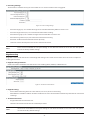
4 Administration and Conguration
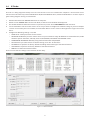
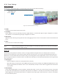
4.1 Live View
Figure 4 - 1: First Login Page
After accessing and login to the IP address of the unit, the screen will be shown as the above screenshot. There are 2 main
options on the upper left side: “Live View” and “Conguration”. While the upper right side indicates your current login user
level with “Logout” option which enables you to log out after pressing. We mainly focus on Live View functionalities in this
chapter and will detail Conguration in the “4.2 Conguration” later.
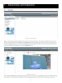
Figure 4 - 2: Live View
After clicking “Live View”, you will be led to real-time live view screen. There are 2 dropdown menus at the left side: language
menu, which is, as its naming, for UI language switch, and player menu, which allows user to change preferred plug-in
Page is loading ...
Page is loading ...
Page is loading ...
Page is loading ...
Page is loading ...
Page is loading ...
Page is loading ...
Page is loading ...
Page is loading ...
Page is loading ...
Page is loading ...
Page is loading ...
Page is loading ...
Page is loading ...
Page is loading ...
Page is loading ...
Page is loading ...
Page is loading ...
Page is loading ...
Page is loading ...
Page is loading ...
Page is loading ...
Page is loading ...
Page is loading ...
Page is loading ...
Page is loading ...
Page is loading ...
Page is loading ...
Page is loading ...
Page is loading ...
Page is loading ...
Page is loading ...
Page is loading ...
Page is loading ...
Page is loading ...
Page is loading ...
Page is loading ...
-
 1
1
-
 2
2
-
 3
3
-
 4
4
-
 5
5
-
 6
6
-
 7
7
-
 8
8
-
 9
9
-
 10
10
-
 11
11
-
 12
12
-
 13
13
-
 14
14
-
 15
15
-
 16
16
-
 17
17
-
 18
18
-
 19
19
-
 20
20
-
 21
21
-
 22
22
-
 23
23
-
 24
24
-
 25
25
-
 26
26
-
 27
27
-
 28
28
-
 29
29
-
 30
30
-
 31
31
-
 32
32
-
 33
33
-
 34
34
-
 35
35
-
 36
36
-
 37
37
-
 38
38
-
 39
39
-
 40
40
-
 41
41
-
 42
42
-
 43
43
-
 44
44
-
 45
45
-
 46
46
-
 47
47
-
 48
48
-
 49
49
-
 50
50
-
 51
51
-
 52
52
-
 53
53
-
 54
54
-
 55
55
-
 56
56
-
 57
57


Messoa SPD983 User manual
- Category
- Security cameras
- Type
- User manual
- This manual is also suitable for
Ask a question and I''ll find the answer in the document
Finding information in a document is now easier with AI
Related papers
Other documents
-
i3 International Ax401C1M & 401C1MN Quick start guide
-
Digitus DN-16063 Datasheet
-
-
Comelit IPPTZ120IR User manual
-
Asoni CAM661H-POE Datasheet
-
-
Eneo GLS-2301H Operating instructions
-
Hunt Electronic HLC-85ED User manual
-
 PheeNet MJCAS-310PTD User manual
-
LevelOne FCS-4041 User manual
