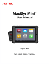
Autel MaxiVCI V200S User manual

Type
User manual

Autel MaxiVCI V200S is a wireless diagnostic interface that connects to a vehicle's diagnostic connector and communicates with a display tablet or standalone PC to transmit vehicle data. It supports wireless BT and USB communication, allowing for easy connection and data transmission. The device features a built-in white LED for illuminating the vehicle data connector socket, as well as indicator lights for power, vehicle connection, and communication status. With a working range of about 32.

Autel MaxiVCI V200S is a wireless diagnostic interface that connects to a vehicle's diagnostic connector and communicates with a display tablet or standalone PC to transmit vehicle data. It supports wireless BT and USB communication, allowing for easy connection and data transmission. The device features a built-in white LED for illuminating the vehicle data connector socket, as well as indicator lights for power, vehicle connection, and communication status. With a working range of about 32.

i
Trademarks
Autel®, MaxiCOM®, MaxiDAS®, MaxiScan®, MaxiTPMS®, MaxiRecorder®, and
MaxiCheck® are trademarks of Autel Intelligent Technology Corp., Ltd., registered in
China, the United States and other countries. All other marks are trademarks or
registered trademarks of their respective holders.
Copyright Information
No part of this manual may be reproduced, stored in a retrieval system or transmitted,
in any form or by any means, electronic, mechanical, photocopying, recording, or
otherwise without the prior written permission of Autel.
Disclaimer of Warranties and Limitation of Liabilities
All information, specifications and illustrations in this manual are based on the latest
information available at the time of printing. Autel reserves the right to make changes at
any time without notice. While information of this manual has been carefully checked for
accuracy, no guarantee is given for the completeness and correctness of the contents,
including but not limited to the product specifications, functions, and illustrations.
Autel will not be liable for any direct damages or for any special, incidental, or indirect
damages or for any economic consequential damages (including the loss of profits).
IMPORTANT: Before operating or maintaining this unit, please read this manual
carefully, paying extra attention to the safety warnings and precautions.
For Services and Support:
pro.autel.com
www.autel.com
1-855-288-3587/1-855-AUTELUS (North America)
0086-755-86147779 (China)
For technical assistance in all other markets, please contact your local distributor.
ii
Safety Information
For your own safety and the safety of others, and to prevent damage to the device and
vehicles upon which it is used, it is important that the safety instructions presented
throughout this manual be read and understood by all persons operating or coming into
contact with the device.
There are various procedures, techniques, tools, and parts for servicing vehicles, as well
as in the skill of the person doing the work. Because of the vast number of test
applications and variations in the products that can be tested with this equipment, we
cannot possibly anticipate or provide advice or safety messages to cover every
circumstance. It is the automotive technicians responsibility to be knowledgeable of the
system being tested. It is crucial to use proper service methods and test procedures. It
is essential to perform tests in an appropriate and acceptable manner that does not
endanger your safety, the safety of others in the work area, the device being used, or
the vehicle being tested.
Before using the device, always refer to and follow the safety messages and applicable
test procedures provided by the manufacturer of the vehicle or equipment being tested.
Use the device only as described in this manual. Read, understand, and follow all safety
messages and instructions in this manual.
Safety Messages
Safety messages are provided to help prevent personal injury and equipment damage.
All safety messages are introduced by a signal word indicating the hazard level.
DANGER: Indicates an imminently hazardous situation which, if not avoided, will
result in death or serious injury to the operator or to bystanders.
WARNING: Indicates a potentially hazardous situation which, if not avoided, could
result in death or serious injury to the operator or to bystanders.
Safety Instructions
The safety messages herein cover situations Autel is aware of. Autel cannot know,
evaluate or advise you as to all of the possible hazards. You must be certain that any
condition or service procedure encountered does not jeopardize your personal safety.
DANGER: When an engine is operating, keep the service area WELL
VENTILATED or attach a building exhaust removal system to the engine exhaust
system. Engines produce carbon monoxide, an odorless, poisonous gas that
causes slower reaction time and can lead to serious personal injury or loss of life.
iii
Do Not Turn the Volume Up Too Loud When Using Headphones
Listening at high volumes that over-stimulate the ear for long periods of time may
result in loss of hearing.
SAFETY WARNINGS:
Always perform automotive testing in a safe environment.
Wear safety eye protection that meets ANSI standards.
Keep clothing, hair, hands, tools, test equipment, etc. away from all moving
or hot engine parts.
Operate the vehicle in a well-ventilated work area, for exhaust gases are
poisonous.
Put the transmission in PARK (for automatic transmission) or NEUTRAL
(for manual transmission) and make sure the parking brake is engaged.
Put blocks in front of the drive wheels and never leave the vehicle
unattended while testing.
Be extra cautious when working around the ignition coil, distributor cap,
ignition wires and spark plugs. These components create hazardous
voltages when the engine is running.
Keep a fire extinguisher suitable for gasoline, chemical, and electrical fires
nearby.
Do not connect or disconnect any test equipment while the ignition is on or
the engine is running.
Keep the test equipment dry, clean, free from oil, water or grease. Use a
mild detergent on a clean cloth to clean the outside of the equipment as
necessary.
Do not drive the vehicle and operate the test equipment at the same time.
Any distraction may cause an accident.
Refer to the service manual for the vehicle being serviced and adhere to
all diagnostic procedures and precautions. Failure to do so may result in
personal injury or damage to the test equipment.
To avoid damaging the test equipment or generating false data, make sure
the vehicle battery is fully charged and the connection to the vehicle DLC
is clean and secure.
Do not place the test equipment on the distributor of the vehicle. Strong
electro-magnetic interference can damage the equipment.
1
Chapter 1 Using This Manual
This manual contains device usage instructions.
Some illustrations shown in this manual may contain modules and optional equipment
that are not included in your system. Contact your sales representative for availability of
other modules and optional tools or accessories.
1.1 Conventions
The following conventions are used.
1.1.1 Bold Text
Bold text is used to highlight selectable items such as buttons and menu
options.
Example:
Tap OK.
1.1.2 Notes
A NOTE provides helpful information such as additional explanations, tips, and
comments.
1.1.3 Important
IMPORTANT indicates a situation which, if not avoided, may result in damage
to the test equipment or vehicle.
1.1.4 Hyperlink
Hyperlinks, or links, that take you to other related articles, procedures, and
illustrations are available in electronic documents. Blue colored text indicates
a selectable hyperlink.
1.1.5 Procedure
An arrow icon indicates a procedure.
Example:
2
To use the camera:
1 Tap the Camera button. The camera screen opens.
2 Focus the image to be captured in the view finder.
3 Tap the blue circle. The view finder now shows the captured picture
and auto-saves the taken photo.
3
2 VCI Wireless Diagnostic Interface
The wireless diagnostic interface MaxiVCI V200S is a small
vehicle communication interface (VCI) used to connect to a vehicles
diagnostic connector (DLC) and connect with the Display Tablet, as well as
standalone PC, as a vehicle communication interface (VCI) for vehicle data
transmission.
2.1 Functional Description
Figure 2-4 MaxiVCI V200S
4
1. Lighting Push Button presses to turn on the white LED in the vehicle
data connector socket
2. Power LED indicates power and system status
Yellow: illuminates solid yellow when powered on and performing self-
check
Green: illuminates solid green when ready for use
Red: flashes red when the firmware is updating
3. Vehicle/Connection LED indicates vehicle and connection status
Green: illuminates green when connected via USB cable; flashes green
when communicating via USB cable
Blue: illuminates blue when connected via Bluetooth; flashes blue when
communicating via Bluetooth
4. Vehicle Data Connector (16-pin) - connects the MaxiVCI V200 to the
vehicles 16-pin DLC directly
5. USB Port - provides the easiest connection between the device and the
display tablet via a USB cable
Communication
The Wireless Diagnostic Interface supports both the wireless BT and the USB
communication. It can transmit vehicle data to the Display Tablet with or without
a physical connection. The working range of the transmitter through BT
communication is about 32.8 feet (about 10 m). A signal lost due to moving out
of range automatically restores itself when the Display Tablet is brought closer
to the VCI unit.
2.2.2 Technical Specifications
Table 2-2 Technical Specifications
Item
Description
Communications
BR/EDR
USB 2.0
Wireless Frequency
2.4 GHz
Input Voltage Range
6 V-36V DC
Supply Current
1A @ DC5V
Operating Temperature
-10°C to 60°C (14°F to 140°F)
Storage Temperature
-40°C to 80°C -40°F to 176°F)
Dimensions (L x W x H)
89.89 mm (3.53”) x 46.78 mm (1.84”) x 21 mm
(0.82”)
Weight
70.7g (0.156 lb.)
Built-in Battery
3.7V Lithium Battery
Light
White LED
2.2.3 Power Sources
The Wireless Diagnostic Interface operates on 12-volt vehicle power, which it
receives through the vehicle data connection port. The unit powers on
whenever it is connected to an OBD II/EOBD compliant data link connector
(DLC).
2.3 FCC STATEMENT
This device complies with Part 15 of the FCC Rules. Operation is subject
to the following two conditions:
(1) This device may not cause harmful interference, and
(2) This device must accept any interference received, including interference that
may cause undesired operation.
Warning: Changes or modifications not expressly approved by the party responsible
for compliance could void the user's authority to operate the equipment.
NOTE: This equipment has been tested and found to comply with the
limits for a Class B digital device, pursuant to Part 15 of the FCC Rules.
These limits are designed to provide reasonable protection against
harmful interference in a residential installation. This equipment
generates uses and can radiate radio frequency energy and, if not
installed and used in accordance with the instructions, may cause harmful
interference to radio communications. However, there is no guarantee
that interference will not occur in a particular installation. If this equipment
does cause harmful interference to radio or television reception, which
can be determined by turning the equipment off and on, the user is
encouraged to try to correct the interference by one or more of the
following measures:
Reorient or relocate the receiving antenna.
Increase the separation between the equipment and receiver.
Connect the equipment into an outlet on a circuit different from that to
which the receiver is connected.
Consult the dealer or an experienced radio/TV technician for help.
FCC Radiation Exposure Statement:
This equipment complies with FCC radiation exposure limits set forth
for an uncontrolled environment. This equipment should be installed
and operated with minimum distance 20cm between the radiator &
your body.
6
WARNING:
Applying a voltage to the ground input is likely to cause permanent damage
to the oscilloscope, the attached computer, and other equipment.
To prevent measurement errors caused by poor grounding, always use the
high-quality USB cable supplied with the oscilloscope.
C. External connections
DANGER:
To prevent injury or death, use only the power cord and adaptor supplied with
the product.
D. Environment
DANGER:
To prevent injury or death, do not use in wet or damp conditions, or around
explosive gas or vapor.
WARNING:
To prevent damage, always use and store your oscilloscope in appropriate
environments. For detailed information on temperature and humidity
specifications for both the storage and usage of the oscilloscope, see 15.1
Safety Information on page 97.
E. Product Maintenance
The product contains no user-serviceable parts. Repair, servicing and calibration
require specialized test equipment and must only be performed by Autel Tech
Support or an approved service provider.
DANGER:
To prevent injury or death, do not use the product if it appears to be damaged
in any way, and stop use immediately if you are concerned by any abnormal
operations.
WARNING:
Do not tamper with or disassemble the oscilloscope, connectors or
accessories. Internal damage will affect performance.
Do not block any of the instruments air vents as overheating will cause
damage to the oscilloscope.
When cleaning the oscilloscope, use wet soft cloth with mild detergent in water.
Do not allow water to enter the oscilloscope casing, as this will cause damage
to the electronics inside.
7
Chapter 19 Warranty
12-Month Limited Warranty
Autel Intelligent Technology Corp., Ltd. (the Company) warrants to the original retail
purchaser of this MaxiCOM Diagnostic Device, that should this product or any part
thereof during normal consumer usage and conditions, be proven defective in material
or workmanship that results in product failure within twelve (12) months period from the
date of delivery, such defect(s) will be repaired, or replaced (with new or rebuilt parts)
with Proof of Purchase, at the Company’s option, without charge for parts or labor
directly related to the defect(s).
The Company shall not be liable for any incidental or consequential damages arising
from the use, misuse, or mounting of the device. Some states do not allow limitation on
how long an implied warranty lasts, so the above limitations may not apply to you.
This warranty does not apply to:
a) Products subjected to abnormal use or conditions, accident, mishandling, neglect,
unauthorized alteration, misuse, improper installation or repair or improper storage;
b) Products whose mechanical serial number or electronic serial number has been
removed, altered or defaced;
c) Damage from exposure to excessive temperatures or extreme environmental
conditions;
d) Damage resulting from connection to, or use of any accessory or other product not
approved or authorized by the Company;
e) Defects in appearance, cosmetic, decorative or structural items such as framing
and non-operative parts.
f) Products damaged from external causes such as fire, dirt, sand, battery leakage,
blown fuse, theft or improper usage of any electrical source.
IMPORTANT: All contents of the product may be deleted during the process of repair.
You should create a back-up copy of any contents of your product before delivering the
product for warranty service.
  • Page 1 1
  • Page 2 2
  • Page 3 3
  • Page 4 4
  • Page 5 5
  • Page 6 6
  • Page 7 7
  • Page 8 8
  • Page 9 9
  • Page 10 10

Autel MaxiVCI V200S User manual

Type
User manual

Autel MaxiVCI V200S is a wireless diagnostic interface that connects to a vehicle's diagnostic connector and communicates with a display tablet or standalone PC to transmit vehicle data. It supports wireless BT and USB communication, allowing for easy connection and data transmission. The device features a built-in white LED for illuminating the vehicle data connector socket, as well as indicator lights for power, vehicle connection, and communication status. With a working range of about 32.

Ask a question and I''ll find the answer in the document

Finding information in a document is now easier with AI