DAYLIFF UVT Installation guide

Type
Installation guide

DAYLIFF UVT is a highly efficient water heating system that utilizes the power of the sun to provide hot water for your home. Featuring individual concentric tube and glass heating elements, a well-insulated storage tank, and a separate cold water header tank, the DAYLIFF UVT delivers exceptional performance even in cloudy or cold conditions.

DAYLIFF UVT is a highly efficient water heating system that utilizes the power of the sun to provide hot water for your home. Featuring individual concentric tube and glass heating elements, a well-insulated storage tank, and a separate cold water header tank, the DAYLIFF UVT delivers exceptional performance even in cloudy or cold conditions.

Installation &
Operating Manual
UVT
VacTubes Solar Systems
SPECIFICATIONS
1.
1
2.
EQUIPMENT SPECIFICATIONS 3
INDEX
© Davis & Shirtliff Ltd 2020
Contents herein are not warranted
8.
TROUBLE SHOOTING 15
9.
TERMS OF WARRANTY 17
3.
SYMBOLS & WARNINGS 4
4.
SITING 5
5.
INSTALLATION 6
6.
SYSTEM COMMISIONING 12
7.
USAGE 13
1
1. SOLAR WATER HEATER SPECIFICATIONS
Ultrasun UVT VacTube Vacuum Tube solar hot water systems are the most
efficient water heating systems available. Solar energy is captured in the
vacuum sealed glass void heating the water in the glass tube. The heated water
rises to the top of the pipe and collects in the tank. The large surface area of the
vacuum tube and high water turbulence within the internal chamber provide
rapid transfer of heat to the water flowing through the tank. The sealed
evacuated tubes and tri-oxide coating provide maximum solar gain even in the
coldest areas and during cloudy or overcast days. System features include;
Ÿ Individual high efficiency concentric tube and glass heating elements
Ÿ Storage tank comprising a stainless steel inner cylinder, plastic painted
insulated galvanised external casing and 1.5kW heating element
Ÿ Separate 8L cold water header tank
Ÿ Anodised aluminum frame
Ÿ Flat roof mounting kit
Ÿ Supplied with 4 extra glass tubes
Due to the limited pressure capacity of vacuum tubes supply must be via the
included header tank and systems must not be connected directly to the main
supply.
Solar Radiation
Working Principle
Cold Water
Hot Water
open to air
Congratulations on selecting a Ultrasun UVT Vactube Solar Hot Water
System. They are manufactured to the highest standards and if
installed and operated correctly will give many years of efcient and
trouble free service. Careful reading of this Installation Manual is
therefore important, though should there be any queries they should
be referred to the equipment supplier.
2
STRUCTURE
SPECIFICATIONS
Capacity: Hot water 200litres, Cold water 8litres
Vacuum tubes: 20pieces
2
Absorber Area: 3.28m
Feeder
Tank
Tube
bracket
Outer
tank
Inner tank
Air vent
Cold
water inlet
Support
structure
For grouting
Feeder Tank Support
Front, horizontal stay channel
Front, diagonal stay channel
Cradle
Main load channel
Tie channel
Diagonal load channel
Air vent
pipe
Side
Cover
Tube
Tail stock
Drain Hot water
outlet
3
2. EQUIPMENT SPECIFICATIONS
The equipment supplied comprises of two principal components, the tank and the
glass tubes which are mounted together on a frame. A schematic layout of the
circulation arrangement is shown below:-
Priming Cock
Feeder
Tank
Air
Vent
Hot Water Out
Drain Plug
¾” Ball Valve
Cold Water In
¾” Non return Valve
For grouting
Left, lower
main load channel
Left tile
channel Left diagonal
load channel
Right, lower
main load channel
Tail Stock
Back right, lower
diagonal stay channel
Left, upper
main load channel
Back Horizontal
stay channel
Left cradle
Back Horizontal
stay channel
Back right, upper
diagonal stay channel
Right cradle
Front diagonal
stay channel
Right diagonal
stay channel
Right upper
main load
channel
4
WARNING
WARNING
WARNING
3. SYMBOLS AND WARNINGS
The installation of the solar system must be in accordance
with the relevant requirements of the local authority
building regulations as well as regulations for the
prevention of accidents when carrying out works such as
solar installation. It is necessary to do so in a safe and
professional manner, taking due care of any aspects of
the works that could result in injuries to the person,
buildings as well as general public.
Work should be preceded by a risk assessment covering
all aspects of health and safety risks, or training
requirements that are reasonably foreseen.
Place the evacuated glass tube collector out of reach of
children.
WARNING
WARNING
Installers must adhere to the valid work protection
regulations, in particular when working on the roof. Anti-
fall protection must be employed whenever there is a risk
of falling.
To avoid the risk of being burned or scalded by hot
components, Installation and replacement of collectors
or parts should be done on cloudy days. Installation work
on sunny days should be carried out only in the morning
or evening or with the collector covered.
WARNING
If there is risk of hailstorms additional protection should
be provided to the evacuated glass tubes by means of a
mesh.
WARNING
The glass tube should not be touched or lled with cold
water if tube has been exposed to sun without water.
WARNING
Immersion heater is intended as standby device for
water heating and should not be used simultaneously.
4
WARNING
It is recommended to use a spanner to x the pipe from
the tank when making any connections.
WARNING
Prevent twisting and axial force to the pipe to avoid
damage to the seal.
WARNING
Hard objects should not be dropped on glass tubes.
WARNING
Blockage or damage to the vent pipe can create severe
damage to the solar water heater. Should this occur, call
the authorized service provider immediately. In case of
emergency, like breakage of tubes or leakage in tank.
Close the cold water inlet and hot water outlet valves
immediately and call authorized service provider for
rectication of problem.
5
WARNING
Do not connect any pressure relief device to the vent pipe
of this solar water heater.
4. SITING
Correct siting is critical for the effective operating of a solar water heater, the
following being important guidelines:-
Orientate the principal axis of the units in a North/South direction, with the
collector facing the equator. This orientation is important to maximise sun
exposure on the collector as it tracks on its East /West axis throughout the
day.
0
Tilt at approx 15 . In order to optimise irradiation. Heater units should never
be laid flat.
Avoid any shade, especially between 10am and 4pm. Shade reduces system
efficiency.
Preferably, solar water heaters should be installed on roofs where solar
irradiation is highest and they are also less exposed to damage. If this is not
possible, a protected ground sitting is acceptable.
6
5. INSTALLATION
1. The location of the solar water heater should be on even surface with plenty of
sunlight and free of shadows between at least 9 am to 4 pm. For installation
North of the Equator it should be installed facing South and vice versa for
installation South of the Equator.
Installation with feeder tank
Feeder
Tank
Fig 2 Fig 3
The frame supplied with the Solar Tank is a dual-purpose frame that can be
used either on a flat roof or on a pitched roof, depending on the assembly
adopted. (See Fig 4)
2. Wherever wind speed is high, the solar water heater should be grouted
properly to the roof of the building. A lightning conductor may be fitted if
required.
Flat Roof
Fig 4 Pitched Roof Stand
7
ŸEnsure that the roof structure is strong enough to take the weight of the
filled tank.
ŸCare should be taken when maneuvering the stand. It is preferably
done by two or more people.
ŸIt is advised that the installer stands over the main roof support
structure.
ŸExtra care should be taken when mounting and dismounting iron
ladders.
3. Fix the stand securely on the roof, ensuring that any fixings used that
penetrate the roof outer surface are fully sealed on completion of the job.
Set the tank in its cradle and secure loosely to the frame with the bolts
provided.
4. The filling point on top of the tank should be at the top as it sits on the
frame so that when the Feeder Tank is in position it stands vertical - this is
important because of the operation of the control valve within the feeder
tank
Working on roof areas is dangerous particularly in
the case of pitched roofs.
CAUTION
At this point of the installation, it may be necessary to adjust the set of the
frame, in order to ensure that the tanks are correctly positioned. This may
include fitting a spacer to the front or back mounting points.
Installing the Feeder Tank
Prior to installing the Feeder Tank, ball valve should be checked to ensure
proper. Every Feeder Tank assembly is individually tested before leaving the
factory, however, vibration in transit sometime causes the valve to dislodge
or jam.
The ball valve is intended for use with a supply pressure
of no more than 4 bars.
CAUTION
5. Install the Feeder Tank on top of the Main Tank.
8
Cross section of standard Feeder Tank showing pipe positions
The Feeder Tank is secured onto its base simply by screwing it onto the inlet
port on top of the Main Tank. This is a standard ¾" BSP pipe-fitting and the
tank should be screwed into position using PTFE (thread) tape.
The final position of the Feeder Tank is correct when the 'inlet' is facing
the end of the Main Tank that it is closest to.
Fig 5
6. Connect the hot water outlet port after the valve with insulated pipeline to the
usage points. It is advised to use either polyethylene-laminated aluminum
pipe or CPVC (N 20 Grade) for the hot water pipe.
Fig 6
9
7. It is advisable to use compression plumbing pipes which can be installed
without tools for cold and hot water usage for ease of installation and
maintenance. They provide better insulation than manually-insulated metal
pipes, and need no insulation of the hot water plumbing if pipe does not
exceed 12 meters. Pipe wrench use is also unnecessary.
8. The distance between points of use and the solar water heater should be
minimized as much as possible, the maximum recommended distance
without heat loss is 12 meters using recommended pipes. For longer
distances proper insulating material should be used to prevent heat loss.
9. Using a spanner, grip the nipple firmly while tightening inlet/outlet pipes to
tank. This is necessary to prevent nipple weld breaking.
Fig 7
10.To reduce heat loss in the pipelines, 3-4 outlet points are recommended. In
case the outlets exceed this or the water line is long, it is recommended to
expand the capacity of the solar water heater. The standard diameter of
inlet/outlet points of the solar water heater 1/2”.
11.In places where the hot and cold water pressure is not equal and mixing
valves are used at the usage point, care should be taken to install either non-
return valve (NRV) based mixer or a NRV on the hot water pipe of each usage
point so as to prevent the reverse flow of hot water.
12. Use soap or oil on glass tubes then insert them into solar water heater tanks.
Cover glass tubes with materials like canvas, cloth or cardboard till the
proper plumbing connections are made and the solar water heater is
supplied with regular cold water. This is to avoid the glass tubes overheating
without water, which could lead to breakage.
Installing Glass Tubes
10
Fig 8
The glass vacuum tubes are inserted into the holes in the underside of the
tank, and the bottom of the tube then retracted into the cradle, on the bottom
of the stand.
The vacuum tubes are made from strengthened glass,
however, caution is required when handling them to
avoid breakages.
CAUTION
Solar tanks are heavily insulated, and the tubes pass through an aperture in
the insulating foam, before engaging with the silicon seal fitted to the inner
tank of the Main Tank. Care must be taken when fitting the tubes to ensure
that no pieces of the foam are dislodged and pushed into the silicon seal with
the tube. This is a common cause of leaks in newly installed tanks.
11
Care must also be taken with the seal itself. The seal is not attached to the
tank; it is located into the fitting hole of the tank and stays in place because it
has a groove all around it. Make sure that each seal is securely in place
before you insert the vacuum tube. When the tube is inserted, it expands the
seal slightly, which presses it against the metal of the tank making it
watertight.
Fit the dust seal, a black/white, slightly dished ring seal supplied with the
tubes. The purpose of this is to exclude dust and dirt from the area around the
silicon seal. Note, this dust seal must be installed on the tube prior to
insertion, and then pushed up to the right position once the tube is fitted.
Aperture containing silicon seal
Fig 9
Fig 10 Dust seals
When inserting the glass tubes into the metal cradle, ensure the white plastic
cup is first located into position on the frame. The glass tube can then be slid
into place.
Ensure that tubes are not exposed to sunlight before
they are to be installed and remain covered at all times.
CAUTION
12
Vacuum Tube Installation
The vacuum tubes supplied with the tank are highly efficient. Left in the sun
and left dry, they will easily attain an internal temperature of over 250°
Celsius a temperature that can cause both damage and injury.
Fig 11
Each tube should be removed from its packaging ONLY
when one is ready to install it. Tubes should ALWAYS be
installed lled with water - to avoid the possibility of
heat damage to the tank.
CAUTION
Ensure cold water is lled early in the morning when the
temperature within the tubes is low to avoid damage to
the glass tubes.
CAUTION
13. After the installation, allow the solar water heater to heat the water for a day
of sunlight before using the hot water.
14. The solar water heater has a provision for back-up electrical heater. It should
be installed by a trained electrician providing a proper earth and protecting
the cable connections from water and moisture.
6. SYSTEM COMISSIONING
On installation or after service it is important that the system is primed. This is
carried out by first opening the incoming feed followed by the bleed cock
and then observing when all air is expended from the bleed outlet. Proper
priming is important or else the unit will not operate at full efficiency.
13
7. USAGE
It is important that the hot water availability is properly managed as solar
energy heating only occurs between the hours of 9:00am - 4:00pm. This
effectively means that hot water is available in the evening as any draw off will
result in temperature reduction from the replacement cold water. If hot water is
required in the morning there should either be no night time draw off or the
booster heater should be used. Users should plan hot water usage
accordingly.
The recommendations below will help to improve the overall efficiency of the
solar water heater.
Hot water will flow from usage point only after unheated water in pipeline
flows out first.
Plan the consumption of hot water in quick intervals at one time (either in
the morning or evening) to minimize heat loss in the pipeline.
Run the hot water slowly, this will avoid the mixing of hot and cold water in
the solar water heater tank.
Do not withdraw more than the rated capacity of the system on a single
day.
Use electrical backup when more hot water is required.
Heating time for 1.5kW element
0
Hours of heating (for 15C rise in temperature)
Litres of Water
1.5kW
75 100 125 150 175 200 225 250 275 300
0
0.5
1
1.5
2
2.5
3
3.5
If a controller is used to turn on the electrical heater automatically, ensure
0
it is set at 45 C . This is usually sufficient for a hot water shower. A higher
setting will increase electricity bills unnecessarily.
Paint the MS support stand once every five years. Though the supporting
structure and other MS parts are powder coated for long rust-free life,
inspect occasionally and paint them if need be.
Regularly inspect the solar water heater tank to make sure it's not
damaged and that no rainwater runs into the tank insulation. Also check
for any rusting in the plumbing lines.
To drain the water from solar water heater (for cleaning or repair),
disconnect the cold water inlet pipe line and open the cold water inlet
valve; If a feeder tank is used, close the cold water inlet valve and remove
the drain pipe dummy to drain the water from the solar water heater tank.
If the water is hard, it is recommended to clean the solar water heater tank
and glass tubes with fresh water once a year to flush out settled scales.
Any repairs or maintenance should be carried out by a qualified
technician.
14
8. TROUBLE SHOOTING
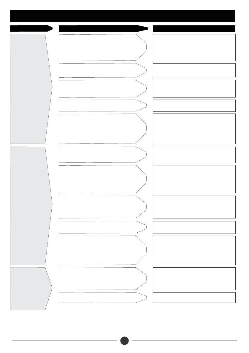
Cold water inlet pipe or hot water
outlet pipe from the solar water
heater is choked by sediment or
scales
Clean the pipes and descale as
necessary
PROBLEM POSSIBLE CAUSE SOLUTION
Wa t e r i s n o t
flowing from the
tap
Cold water inlet valve is shut Open the valve
Float valve in the feeder tank has
jammed or choked Clean the float valve or replace it
Non return valve stuck Clean the NRV or replace it
Air is trapped in the cold or hot water
pipe line
Open the hot water outlet pipe near
the valve and bleed the air or drain
the water out of the tank and fill the
solar water heater again
The solar water heater is not
receiving enough sun light Expose heater to sunlight
Excessive water consumption
(undersized)
Plan water usage as per installed
c a p a c i t y. I n c a s e o f h i g h
consumption use the electric back-
up
Not getting hot
water
Incorrect connection of cold water
and hot water pipes to solar water
heater storage tank
Shorten the hot water plumbing line
or increase the capacity of the
system.
Cloudy day, not enough sun light Use the electrical back-up
Cold water pressure due to mixing
valve preventing the hot water
coming through
Run hot water slowly at first and then
gradually open up the cold water tap
for optimal mixing of hot and cold
water at the point of use
System not in use for a long time
If the system is not being used, cover
the glass tubes with a shade or install
a steam trap on the air vent.
Water is boiling
and steam is
being released
from vent Failure of controller Repair/ replace the controller
15
16
PROBLEM POSSIBLE CAUSE SOLUTION
Wrong wiring connections Check wiring
E l e c t r i c a l
b a c k u p n o t
working
Inappropriate set temperature Set the controller for a comfortable
0
bath between 35-45 C
Lighting strike Inspect/replace fuse, heater element
and thermostat
Short circuit Inspect/replace fuse, heater element
and thermostat
Failure of controller Repair/ replace the controller
The solar water heater or plumbing
line has a leak
Determine the source of the leakage
and fix. If the problem persists, call
authorised service provider
The solar water
h e a t e r i s
leaking
Reverse flow of cold water in the
solar water heater tank (in case of
mixing valve)
Close cold and hot water tap of the
mixing valve
W a t e r o v e r
flows from air
vent or feeder
tank
Inappropriate air vent length Increase the length of the air vent as
per installation guidelines
Float valve stuck in the feeder tank Clean or replace the float valve in
the feeder tank
17
9. TERMS OF WARRANTY
i) General Liability
ii) Standard Warranty
In lieu of any warranty, condition or liability implied by law, the liability of
Dayliff (hereafter called the Distributor) in respect of any defect or failure
of equipment supplied is limited to making good by replacement or
repair (at the Distributor’s discretion) defects which under proper use
appear therein and arise solely from faulty design, materials or
workmanship within a specified period. This period commences
immediately after the equipment has been delivered to the
customer and at its termination all liability ceases. Also the warranty
period will be assessed on the basis of the date that the Distributor is
informed of the failure.
ŸThis warranty applies solely to equipment supplied and no claim for
consequential damages, however arising, will be entertained. Also the
warranty specifically excludes defects caused by fair wear and tear, the
effects of careless handling, lack of maintenance, faulty installation,
incompetence on the part of the equipment user, Acts of God or any
other cause beyond the Distributors's reasonable control. Also, any
repair or attempt at repair carried out by any other party invalidates all
warranties.
General Terms
If equipment failure occurs in the normal course of service having been
competently installed and when operating within its specified duty limits
warranty will be provided as follows:-
ŸUp to 3 years- The item will be replaced or repaired at no charge.
ŸOver 3 years, less than ve years - The item will be replaced or
repaired at a cost to the customer of 50% of the Davis & Shirtliff
market price.
The warranty on equipment supplied or installed by others is conditional
upon the defective unit being promptly returned free to a Davis &
Shirtliff ofce and collected thereafter when repaired. No element of site
repair is included in the warranty and any site attendance costs will be
payable in full at standard chargeout rates.
INS465A-09/20
  • Page 1 1
  • Page 2 2
  • Page 3 3
  • Page 4 4
  • Page 5 5
  • Page 6 6
  • Page 7 7
  • Page 8 8
  • Page 9 9
  • Page 10 10
  • Page 11 11
  • Page 12 12
  • Page 13 13
  • Page 14 14
  • Page 15 15
  • Page 16 16
  • Page 17 17
  • Page 18 18
  • Page 19 19
  • Page 20 20

DAYLIFF UVT Installation guide

Type
Installation guide

DAYLIFF UVT is a highly efficient water heating system that utilizes the power of the sun to provide hot water for your home. Featuring individual concentric tube and glass heating elements, a well-insulated storage tank, and a separate cold water header tank, the DAYLIFF UVT delivers exceptional performance even in cloudy or cold conditions.

Ask a question and I''ll find the answer in the document

Finding information in a document is now easier with AI