Topcraft FOP-210501 User manual

Category
Fireplaces
Type
User manual

Topcraft FOP-210501 is a portable electric air pump that offers quick inflation and deflation with its powerful motor, aiding in various applications like inflating tires, sports balls, and pool toys, as well as deflating air mattresses and other inflatables. It features a compact and lightweight design for easy portability, making it an ideal companion for on-the-go inflation needs.

Topcraft FOP-210501 is a portable electric air pump that offers quick inflation and deflation with its powerful motor, aiding in various applications like inflating tires, sports balls, and pool toys, as well as deflating air mattresses and other inflatables. It features a compact and lightweight design for easy portability, making it an ideal companion for on-the-go inflation needs.

ANS Z21.97 CSA 2.41-2017
Outdoor Decorative Gas Appliances
03
INSTALLER: Leave this manual with the appliance.
CONSUMER: Retain this manual for future reference WARNING: For Outdoor Use Only.
DANGER
FIRE OR EXPLOSION HAZARD
WARNING
Do not store or use gasoline, or other
flammable vapors and liquids,in the
vicinity of this or any other
appliance.
An LP-cylinder not connected for use
shall not be stored in the vicinity of
this or any other appliance.
Installation and service must be
performed by a qualified installer,
service agency, or the gas supplier.
DANGER
CARBON MONOXIDE HAZARD
This appliance can produce carbon monoxide which has no odor.
Using it in an enclosed space can kill you.
Never use this appliance in an enclosed space such as a camper,
tent, car or home.
WARNING:
If the information in this manual is not followed exactly, a fire or explosion may result causing
property damage, personal injury, or loss of life.
If you smell gas:
Shut off gas to the appliance.
Extinguish any open flame.
If odor continues, leave the area immediately.
After leaving the area, call your gas supplier or fire
department.
Failure to follow these instructions could result in
fire or explosion, which could cause property
damage, personal injury, or death.
IMPORTANT SAFETY INFORMATION
The installation must conform with local codes or, in the absence of local codes, with the National Fuel Gas
Code, ANSI Z223.1 NFPA 54; National Fuel Gas Code; Natural Gas and Propane Installation Code, CSA
B149.1; or Propane Storage and Handling Code, CSA B149.2, as applicable.
The appliance must be isolated from the gas supply piping system by closing its individual manual shutoff valve
during any pressure testing of the gas supply piping system at test pressures equal to or less than 1/2 psi (3.5
kPa).
The maximum inlet gas supply pressure is 250 psi.
The appliance area must be kept clear and free from combustible materials, gasoline, and other flammable
vapors and liquids.
Do not use this appliance if any part has been under water. Immediately call a qualified service technician to
inspect the appliance and to replace any part of the control system and any gas control that has been under water.
Children and adults should be alerted to the hazards of high surface temperatures and should stay away
to avoid burns or clothing ignition.
Young children should be carefully supervised when they are in the area of the appliance.
Clothing or other flammable materials should not be hung from the appliance or placed on or near the
appliance.
Any guard or other protective device removed for servicing the appliance shall be replaced prior to
operating the appliance.
Installation and repair should be done by a qualified service person. The appliance should be inspected
before use and at least annually by a qualified service person. More frequent cleaning may be required
as necessary. It is imperative that the control compartment, burners, and circulating air passageways of
the appliance are kept clean.
CAUTION: The propane gas pressure regulator provided with this appliance must be used. This regulator is set
for an outlet pressure of 11 inches water column.
DO NOT burn solid fuels in this appliance.
This outdoor gas appliance is for Outdoor Use ONLY.
This outdoor gas appliance is not intended to be installed in or on recreational vehicles and/or boats.
This outdoor appliance is not for use on wood decks or other flammable surface.
Before each use of this gas appliance, open the door and/or the LP (Liquid Propane) Tank Drawer and inspect
the hose. If there is evidence of excessive abrasion or wear or if the hose is damaged, the hose assembly must
be replaced prior to the appliance being put into operation. Use only the replacement hose assembly specified in
this manual. Make sure to leak test.
Before each use of this gas appliance, inspect the burner. The burner must be replaced prior to the appliance
being put into operation if it is evident that the burner is damaged. Use only the replacement burner specified in
this manual.
Make sure to properly locate the gas hose including locating the hose out of pathways where people may trip
over it or in areas where the hose may be subject to accidental damage.
Keep the fuel supply hose away from any heated surface.
Never use this appliance closer than 10 feet from anything flammable, including houses or overhead tree
branches.
Never use gasoline, kerosene, or any other liquid fuel to start a fire.
Always maintain a safe distance from the fire.
Always supervise children around the fire.
Never leave a fire unattended.
The appliance is hot during and after use, always allow ample cooling time before touching or moving.
1.
2.
3.
4.
5.
6.
7.
8.
9.
10.
11.
12.
13.
14.
15.
16.
17.
18.
19.
20.
21.
22.
23.
24.
25.
04
WARNING: THIS PRODUCT CAN EXPOSE YOU TO
CHEMICALS INCLUDING CHROMIUM (HEXAVALENT
COMPOUNDS) AND BENZENE, WHICH ARE KNOWN TO THE
STATE OF CALIFORNIA TO CAUSE CANCER AND BIRTH
DEFECTS OR OTHER REPRODUCTIVE HARM.
For more information go to:
www.P65warnings.ca.gov/furniture.
IMPORTANT SAFETY INFORMATION ABOUT
PROPANE (LP) GAS
The LP-gas supply cylinder to be used must be constructed and marked in accordance with the U.S. Deparment
of Transportation (D.O.T.) Specifications for LP-Gas Cylinders, or the Standard for Cylinders, Spheres and Tubes
for Transportation of Dangerous Goods and Commission, CAN/CSA-B339, as applicable.
The LP-gas supply cylinder to be used must have a listed overfilling prevention device (See Figure 1).
The LP-gas supply cylinder to be used must have a cylinder connection device compatible with the connection for
the appliance.
A self-contained LP-gas cylinder for use with this appliance must have a capacity of 20 Ibs cylinder (Height
approximately 18 in., Tank Body approximately 12 in. diameter, Base approximately 8 in. diameter).
The cylinder supply system must be arranged for vapor withdrawl.
The cylinder used must include a collar to protect the cylinder valve.
This appliance shall be used only outdoors in a well-ventilated space and shall not be used in a building, garage
or any other enclosed space.
When this appliance is not in use, the gas must be turned off at the supply cylinder.
Storage of this appliance indoors is permissible only if the cylinder is disconnected and removed from the appli-
ance.
Cylinders must be stored outdoors in a well-ventilated area out of the reach of children. Disconnected cylinders
must have threaded valve plugs tightly installed and must not be stored in a building, garage or anyother
enclosed areas.
This appliance is certified by CSA (Canadian Standards Association) to ANS Z21.97 CSA 2.41-2017, Outdoor
Decorative Gas Appliances.
1.
2.
3.
4.
5.
6.
7.
8.
9.
10.
11.
Rated Heat Input (Liquid Propane)
Propane Regulator Pressure
Clearance to combustible surfaces
40,000 BTU/hr
11 inches water column
Sides: 24in. (610mm), Top: 72in. (1829mm)
05
Standard 20 Ib.tank
Figure 1
SPECIFICATIONS
D
pilot box
A
PART DESCRIPTION QUANTITY
A 1 pc
B 1 pc
C
1 pc
D 1 box
Weather cover
Fire table
Tank seat
Lava rock (6.6 Ibs)
BC
D
06
Figure 2
ASSEMBLY INSTRUCTIONS
1.
2.
PACKAGE CONTENTS
Carefully unpack all parts from the box, compare parts with package content listed above, make sure all parts
are present before beginning assembly of product. If any part is missing or damaged, do not attempt to assem-
ble the product. Contact customer service for replacement parts.
Open the box of lava rocks, put the lava rocks (D) into the fire bowl of the fire table (A) (See Figure 2). A gas
fire pit requires 6.6 lbs lava rocks.
WARNING: keep children away during assembly, as this item contains lava rock, which are small pieces and
can be swallowed by children.
NOTE: leave the pilot box uncovered by the lava rock.
CAUTION: Please be advised that this fire pit is equipped with natural lava rock that may crackle or pop the
first time it is used. The lava rock has been pre-heat treated to release any natural inherent moisture. How-
ever, in rare cases on first time use, the lava rock may pop or burst causing small pieces of hot rock to
potentially be a projectile. These hot pieces could cause injury or property damage. As a precaution, please
follow these instructions the first time the fire pit is used:
(1). On first use, do not stand over or near the fire pit once lit.
(2). Light the fire pit and let it run on high for 20 minutes.
(3). Once lit, do not go within 12 feet of the fire pit for at least the first 20 minutes on the first use to ensure
any residual moisture trapped in the rocks gets released.
(4). After the first heating cycle there is little further concern. It is rare that any crackling will happen on the
first use, this is simply a precaution.
(5). Keep lava rock covered and dry while not in use to prevent additional moisture from getting in the rocks.
(6). If lava rocks are exposed to moisture after first use, run the burner on low to gradually warm and dry the
rocks before repeating steps 1 through 3.
C
retention point
D
B
40
4. Secure the cylinder by tightening clockwise the retention point found on the tank seat (B) (see Figure 4), so
that the cylinder cannot move from side to side or fall down.
NOTE: fire pit and gas tank must have the minimum distance of 40 inches.
WARNING: make sure to properly locate the gas hose by keeping it out of pathways where people may tip
over it or in an area where the hose may be subject to accidental damage.
Figure 3
Figure 4
3.
Put the gas tank in the tank seat (B), connect the regulator, screw the black handle clockwise to tighten, turn
the black handle counterclockwise to remove. The hose must not turn upside. The knob on the control panel is
turned all the way to the “OFF” position when the fireplace is NOT in use (see Figure 3).
black handle
07
Figure 5
5. Cover the fire pit with the outdoor Weather cover (C) when not in use to protect it from the elements or when
fire pit is cool COMPLETELY after the use (See Figure 5).
OFF (APG.)
MAX
(MÁX.)
1 AAA
1.5V
IGNITOR
( Encendedor )
ON/MIN
(ENC./MÍN.)
LIGHTING INSTRUCTIONS
1. Push in gas control knob slightly and
2. Turn gas control knob to “ON/MIN”.
3. Push in gas control knob all the way
4. If the burner does not light in 15
1. Push in gas control knob slightly and turn to “OFF”.
TO TURN OFF GAS
INSTRUCCIONES DE ENCENDIDO
PARA CERRAR EL GAS
1. Presione ligeramente la perilla de control del gas y gírela a la
2. Gire la perilla de control del gas a “ENC/MÍN” (encendido/mínimo).
3. Presione la perilla de control del gas hasta el fondo y mantenga presionada.
4. Si el quemador no se enciende en 15 segundos, suelte la perilla y esta
encender el quemador nuevamente, repita los pasos 1 al 3.
1. Presione ligeramente la perilla de control del gas y gírela a la
turn to “OFF”.
and hold. Continue to press the
ignition button for 15 seconds.
seconds, release the knob and it will
pop back out. Wait 5 minutes before attempting
to light the burner again, repeat step 1 to 3.
posición “APG” (apagado).
Siga presionando el botón de encendido durante 15 segundos.
volverá a su posición hacia afuera. Espere 5 minutos antes de intentar
posición “APG” (apagado)
08
Figure 6
BATTERY
Leak Test
WARNING:
Make sure the control knob is in the “OFF” position. Unscrew the push button cap on the ignitor module located
on the control panel to access the battery compartment. The ignitor module requires one AAA size battery (See
Figure 6),
BATTERY IS NOT INCLUDED.
1. Please observe proper polarity and use the correct battery type when placing or replacing the battery.
Improper installation could result in ignition failure.
2. Please remove the battery if consumed or if product is to be left unused for a long period of time.
1. Always perform the leak test as described below before lighting this appliance or each time the
cylinder is connected for use.
2. Do not smoke or allow other sources of ignition in the area while conducting a leak test.
3. Conduct the leak test outdoors in a well-ventilated area.
4. Do not use matches, lighters or a flame to check for leaks.
5. Do not use this appliance until any and all leaks are corrected. If you are unable to stop a leak,
disconnect the propane supply. Call a gas appliance service shop or your local propane gas supplier.
To prevent fire or explosion hazard when testing for a leak:
cylinder-regulator connection (Figure 7) gas valve-bellows connection (Figure 8)
OFF (APG.)
MAX
(MÁX.)
1 AAA
1.5V
IGNITOR
( Encendedor )
ON/MIN
(ENC./MÍN.)
LIGHTING INSTRUCTIONS
1. Push in gas control knob slightly and
2. Turn gas control knob to “ON/MIN”.
3. Push in gas control knob all the way
4. If the burner does not light in 15
1. Push in gas control knob slightly and turn to “OFF”.
TO TURN OFF GAS
INSTRUCCIONES DE ENCENDIDO
PARA CERRAR EL GAS
1. Presione ligeramente la perilla de control del gas y gírela a la
2. Gire la perilla de control del gas a “ENC/MÍN” (encendido/mínimo).
3. Presione la perilla de control del gas hasta el fondo y mantenga presionada.
4. Si el quemador no se enciende en 15 segundos, suelte la perilla y esta
encender el quemador nuevamente, repita los pasos 1 al 3.
1. Presione ligeramente la perilla de control del gas y gírela a la
turn to “OFF”.
and hold. Continue to press the
ignition button for 15 seconds.
seconds, release the knob and it will
pop back out. Wait 5 minutes before attempting
to light the burner again, repeat step 1 to 3.
posición “APG” (apagado).
Siga presionando el botón de encendido durante 15 segundos.
volverá a su posición hacia afuera. Espere 5 minutos antes de intentar
posición “APG” (apagado)
09
LIGHTING INSTRUCTIONS
Make 2~3 oz. of leak solution by mixing one part liquid dishwashing detergent and three parts water. Noted:
make sure control knob is “OFF”.
Apply several drops of solution where the cylinder attaches to regulator (See Figure 7), inspect the solution
at the connection looking for bubbles. If NO bubbles appear, the connection is secure. If bubbles appear, the
connection has the leak, disconnect the regulator, reconnect, perform another leak check. If you continue to
see bubbles after several attempts, cylinder valve is defective and should be returned to cylinder’s supplier.
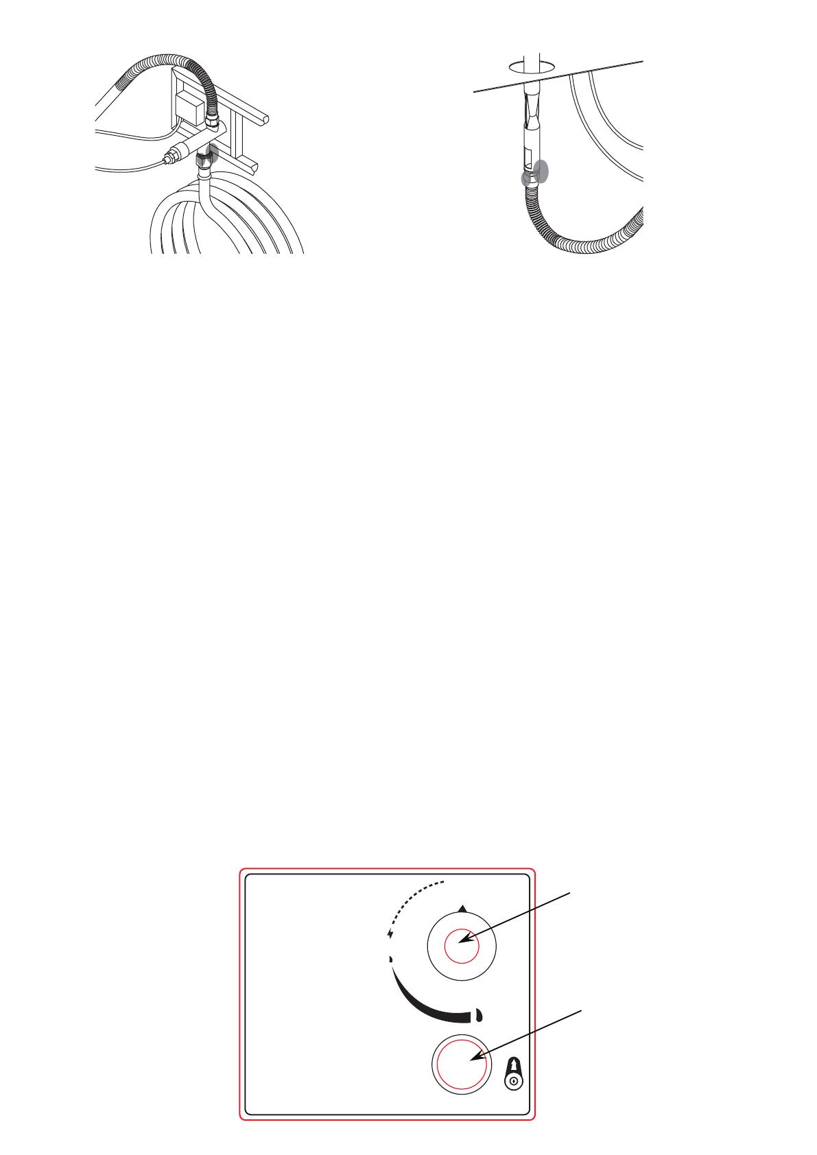
Apply several drops of solution where gas valve attaches to bellows (See Figure 8), where gas valve attaches
to hose (See Figure 9), and where inlet tube attaches to bellows (See Figure 10). If NO bubbles appear, the
connections are secure. If bubbles appear, the connection has the leak, disconnect, reconnect,perform
another leak check. If you continue to see bubbles after several attempts, the part is defective and should
replace the part.
1. Push in gas control knob slightly and turn to “OFF”.
2. Turn gas control knob the “ON/MIN”.
3. Push in gas control knob all the way and hold. ontinue to press the ignition button for 15 seconds.
4. If the burner does not light in 15 seconds, release the knob and it will pop back out. Wait 5 minutes before
attempting to light the burner again, repeat step 1 to 3.
WARNING: For your safety, read and follow the Lighting Instructions in this manual and in the Rating Plate on
the appliance. IMPROPER LIGHTING PROCEDURES COULD RESULT IN A FIRE HAZARD OR
EXPLOSION HAZARD OR PROPERTY DAMAGE, INJURY OR LOSS OF LIFE.
TO TURN OFF GAS
1. Push in gas control knob slightly and turn to “OFF”.
To perform a leak test:
gas valve-hose connection (Figure 9) inlet tube-bellows connection (Figure 10)
Figure 11
1.
2.
3.
gas control knob
ignition button
10
Figure 12
CARE AND MAINTENANCE
Yellow
Yellow
Light Blue
Light Blue
Blue Blue
Good Bad
Observe Flame Height When Lit: The burner will display blue and yellow flames. These flames should be a blue /
yellow color between 1~2 in. height, (See Figure 12). These flames should not be yellow or produce thick smoke.
This would indicate an obstruction of airflow through the burners. The flames should be blue with straight yellow tops.
If excessive yellow flames are detected, turn off the burner and consult “Troubleshooting".
To enjoy the outstanding performance from your fire pit, make sure you perform the following
activities on a regular basis:
1. Use warm soapy water for cleaning. Never use flammable or corrosive cleaning agents.
2. Remove dirt, spills or stains on the product quickly.
3. Dry the product with a soft cloth or paper towel.
4. Do not use sharp tools to scratch the product.
5. While cleaning the fire pit, make sure to keep the area around the burner dry at all times. DO NOT
submerge the control valve assembly. If the gas control is submerge in water, DO NOT use it.
It must be replaced.
6. Air flow must be unobstructed. Keep controls, burner, and circulating air passageways clean.
Signs of possible blockage include:
(1). Gas odor with extreme yellow tipping of flame.
(2). Fire pit does NOT reach the desired temperature.
(3). Fire pit flame is excessively uneven.
(4). Fire pit makes popping noises.
(5). Spiders and insects can nest in burner or orifice. This dangerous condition can damage fire
pit and render it unsafe for use. Clean burner holes by using a heavy-duty pipe clearer.
Compressed air may help clear away small particles.
7. Carbon deposits may create a fire hazard. Clean burner with warm soapy water
if any carbon deposits develop.
8. Cover your fire pit with an outdoor weather cover when not in use to protect it from the elements.
NOTE: Always allow fire pit to cool COMPLETELY before you cover the fire pit with an outdoor
weather cover or you attempt the service or maintenance.
9. NOTE: Always dry the product completely before it is covered or stored into the garage.
REPLACEMENT PARTS LIST
DESCRIPTIONPART# NO
Firepit thermocouple, 350 mm/14"
1
2
3
4
5
6
7
Firepit pulse ignition
Firepit regulator 90 degree hose 3048 mm/120"
Firepit electrode 3" tip, wire 350 mm for 40000, 50000 BTU
Fire table
Weather cover
Firepit lava rock (red), 6.6 lbs
F210045-FT
F210045-WC
FM-LVRK-6.6
EFP-THRMCPL
CLTN-PLSELT
HA-3048-90
ET-E5-350
11
If instructions or parts are missing, please email us at [email protected]
12
WARRANTY
Firepits
Burner, steel fire pit bowl, all mechanical parts and fittings to control panel and burner assembly, and all fire pit
tops that are not cast aluminum are warranted for a period of one (1) year from original date of purchase,
against defects in material and or workmanship. Rust is not covered.
Frames
Frames are warranted to be free from defects in materials and workmanship for a period of one (1) year.
Damage to frames or welds due to improper assembly or exposure to water and sub-freezing temperatures, is
not covered. Breakage that is a result of product being dropped, acts of God, acts of war, etc. are not covered.
Finish
The finish is warranted against peeling, cracking, or blistering for a period of one (1) year provided the product
has not been scratched or abraded. Scratches and chips resulting from normal wear and tear are not covered.
Fading resulting from exposure to elements is not covered. Stains as a result of chemical spills and certain
food items are not covered.
Table Tops
All table tops are warranted for a period of one (1) year from original date of purchase, against defects in
material and or workmanship. Breakage, discoloration, staining, and or any other weather related issues are
not covered.
Warranty Exclusions
Failure caused by unreasonable or abusive use. Firepits that were clearance items, display models or items
purchased in an "as is" condition, freight damage, firepit damaged by acts of nature, vandalism, fire, abuse, lack
of proper care and maintenance, or improper assembly; straps and normal fading or discoloration from exposure
to elements, oils, spills, fluids or chemicals; Table top against breakage; hardware against corrosion or rusting;
buckling or splitting of tubing resulting from exposure to water and freezing temperatures; glass table tops,
purchased or replacement parts; plastics. Also excluded: loss of use of time and or inconvenience, money,
travel, packaging or any other consequential or incidental damages. In no event shall our side responsibility
exceed the value of the replacement product. Warranty is to the original purchaser when items are purchased
from one of our authorized retailers and is not transferable. All warranty claims must be submitted with a dated
register receipt within the warranty period. Should replacement of the warranted item be unavailable, our side
reserves the right to substitute items of our choice similar in style, color and quality. For quality control purposes
and verification, we reserve the right to request photographs of the damage item(s). The terms of this warranty
are subject to change without notice.
  • Page 1 1
  • Page 2 2
  • Page 3 3
  • Page 4 4
  • Page 5 5
  • Page 6 6
  • Page 7 7
  • Page 8 8
  • Page 9 9
  • Page 10 10

Topcraft FOP-210501 User manual

Category
Fireplaces
Type
User manual

Topcraft FOP-210501 is a portable electric air pump that offers quick inflation and deflation with its powerful motor, aiding in various applications like inflating tires, sports balls, and pool toys, as well as deflating air mattresses and other inflatables. It features a compact and lightweight design for easy portability, making it an ideal companion for on-the-go inflation needs.

Ask a question and I''ll find the answer in the document

Finding information in a document is now easier with AI