Operation & Setting
4
TIME SETTING AND FREE WEEKLY PROGRAMMING
Hold down the [ON/standby] and [Functions] buttons together for at least 3 seconds. The hour numbers
will start to ash. Use [+] and [-] to set the current hour and press the [Functions] button to conrm. Set the
current minutes and day in the same way. The latter is indicated by a corresponding point on the vertical
numbered scale, gure 5 below.
Operation & Setting
4
PILOT-WIRE MODE
The locally set high temperature in
comfort mode is modified according to
the controls received from the Pilot-Wire
unit, except in the case where the Pilot-Wire is not connected, or with class 1 regulators (products with
an earth connection).
NOTE: if the Pilot Wire is not installed in the system, the predened operating mode is “Comfort”. In this
case, do not connect the Pilot Wire cable of the thermostat to the earth cable and insulated it.
The programs P1, P2 and P3 are completely independent of
one another and can only be used one at a time. If one of
these is selected (for example P3), the display appears as in
gure 8. The ashing dash (in grey in gure 8) indicated
the time interval currently active.
4. KEY LOCK
This function allows you to block the use of the keys. It may be useful to activate this
setting to avoid accidental changing of settings by unauthorised persons or children. To
activate it, hold down the [+] and [-] keys together for at least 3 seconds. A padlock icon
appears when the keys are locked, figure 4.
With the key lock active, it is still possible to put the thermostat in standby or in operation by pressing the [ON/Standby] button, but it is not possible to
change the temperature setting and the operating mode.
To deactivate the function, hold down the [+] and [-] keys together again for at least 3 seconds. The padlock icon disappears and the buttons resume
the normal functions.
For safety reasons, always prevent children playing with this product.
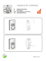
5. TIME SETTING AND FREE WEEKLY PROGRAMMING
Hold down the [ON/standby] and [Functions] buttons together for at least 3 seconds. The hour numbers will start to flash. Use [+] and [-] to set the
current hour and press the [Functions] button to confirm. Set the current minutes and day in the same way. The latter is indicated by a corresponding
point on the vertical numbered scale, figure 5.
After the time, proceed to the weekly programming. Set the sequence for each hour and for each day of the
week. The selection is made using the [+] and [-] keys; at that time [+] regulates the high temperature and [-] the
low temperature. On the time setting bar, a dash corresponds to the high temperature and the empty space
corresponds to the low temperature. Press the [Functions] button to save the day and start the next day with the
same procedure. For example, to have a high temperature from 6 to 10 a.m. and from 7 to 11 p.m. (and a low
temperature in the remaining intervals), see figure 6.
If the [ON/Standby] button is pressed when setting the time and the weekly programming, the electronic thermostat goes into standby status and the
new time/date setting is saved, while the new weekly programming is not saved. Pressing the [ON/Standby] button again brings the thermostat into the
present status before starting the procedure for setting the time.
If there is an interruption in the 230V ac power supply, the weekly programming made remains in the memory, along with the current mode (including
keyboard lock) and the high and low temperature settings, while the time must be reset. When the 230V ac power returns, if one of the chrono modes
is selected (free weekly programming P1, P2 or P3) the “Chrono” symbol flashes and the writing on the display (the current time or P1, P2 and P3
depending on the mode): in this case, follow the procedure illustrated at the start of the paragraph to reset the current time. Until the operation is
performed, the thermostat provisionally counts the time that passes from the moment the 230V ac power returns (and this “provisional” time is used if
one of the chrono modes is selected).
6. INTEGRATED WEEKLY PROGRAMMING
As well as the classic weekly programming defined by the user, the electronic thermostat has 3 integrated programs named respectively P1, P2 and
P3. To change from one to another, press the [Functions] button to select the desired mode as in figure 7.
Modes P1, P2 and P3 are fixed and are set as follows:
The programs P1, P2 and P3 are completely independent of one another and can only be used one at a time. If one of these is selected (for example
P3), the display appears as in figure 8.
The flashing dash (in grey in figure 8) indicated the time interval currently active.
If the user wants to use a weekly program other than P1, P2 or P3, he can make one with his own settings using the standard chrono program
illustrated in the previous paragraph.
7. PILOT-WIRE MODE
The locally set high temperature in comfort mode is modified according to the controls received from the Pilot-Wire unit, except in the case where the
Pilot-Wire is not connected, or with class 1 regulators (products with an earth connection).
The thermostat recognises 6 controls: comfort, reduction (high temperature -3.5°C), stop, antifreeze (7°C), eco1 (high temperature -1°C) and eco2
(high temperature -2°C). The display appears as in figure 9.
Figure 5: Time and day of the week
Figure 4: Key lock active
where:
= high temperature (“Comfort”);
= low temperature (“ECO”).
Regulating set point
Figure 6: Free weekly
programming
Figure 7: Operating modes
Point indicating the day of the week
Numbered scale of the days of the week
Chrono operating mode icon
Figure 8: Program P3 active.
4. KEY LOCK
This function allows you to block the use of the keys. It may be useful to activate this
setting to avoid accidental changing of settings by unauthorised persons or children. To
activate it, hold down the [+] and [-] keys together for at least 3 seconds. A padlock icon
appears when the keys are locked, figure 4.
With the key lock active, it is still possible to put the thermostat in standby or in operation by pressing the [ON/Standby] button, but it is not possible to
change the temperature setting and the operating mode.
To deactivate the function, hold down the [+] and [-] keys together again for at least 3 seconds. The padlock icon disappears and the buttons resume
the normal functions.
For safety reasons, always prevent children playing with this product.
5. TIME SETTING AND FREE WEEKLY PROGRAMMING
Hold down the [ON/standby] and [Functions] buttons together for at least 3 seconds. The hour numbers will start to flash. Use [+] and [-] to set the
current hour and press the [Functions] button to confirm. Set the current minutes and day in the same way. The latter is indicated by a corresponding
point on the vertical numbered scale, figure 5.
After the time, proceed to the weekly programming. Set the sequence for each hour and for each day of the
week. The selection is made using the [+] and [-] keys; at that time [+] regulates the high temperature and [-] the
low temperature. On the time setting bar, a dash corresponds to the high temperature and the empty space
corresponds to the low temperature. Press the [Functions] button to save the day and start the next day with the
same procedure. For example, to have a high temperature from 6 to 10 a.m. and from 7 to 11 p.m. (and a low
temperature in the remaining intervals), see figure 6.
If the [ON/Standby] button is pressed when setting the time and the weekly programming, the electronic thermostat goes into standby status and the
new time/date setting is saved, while the new weekly programming is not saved. Pressing the [ON/Standby] button again brings the thermostat into the
present status before starting the procedure for setting the time.
If there is an interruption in the 230V ac power supply, the weekly programming made remains in the memory, along with the current mode (including
keyboard lock) and the high and low temperature settings, while the time must be reset. When the 230V ac power returns, if one of the chrono modes
is selected (free weekly programming P1, P2 or P3) the “Chrono” symbol flashes and the writing on the display (the current time or P1, P2 and P3
depending on the mode): in this case, follow the procedure illustrated at the start of the paragraph to reset the current time. Until the operation is
performed, the thermostat provisionally counts the time that passes from the moment the 230V ac power returns (and this “provisional” time is used if
one of the chrono modes is selected).
6. INTEGRATED WEEKLY PROGRAMMING
As well as the classic weekly programming defined by the user, the electronic thermostat has 3 integrated programs named respectively P1, P2 and
P3. To change from one to another, press the [Functions] button to select the desired mode as in figure 7.
Modes P1, P2 and P3 are fixed and are set as follows:
The programs P1, P2 and P3 are completely independent of one another and can only be used one at a time. If one of these is selected (for example
P3), the display appears as in figure 8.
The flashing dash (in grey in figure 8) indicated the time interval currently active.
If the user wants to use a weekly program other than P1, P2 or P3, he can make one with his own settings using the standard chrono program
illustrated in the previous paragraph.
7. PILOT-WIRE MODE
The locally set high temperature in comfort mode is modified according to the controls received from the Pilot-Wire unit, except in the case where the
Pilot-Wire is not connected, or with class 1 regulators (products with an earth connection).
The thermostat recognises 6 controls: comfort, reduction (high temperature -3.5°C), stop, antifreeze (7°C), eco1 (high temperature -1°C) and eco2
(high temperature -2°C). The display appears as in figure 9.
Figure 5: Time and day of the week
Figure 4: Key lock active
where:
= high temperature (“Comfort”);
= low temperature (“ECO”).
Figure 6: Free weekly
programming
Figure 7: Operating modes
Point indicating the day of the week
Numbered scale of the days of the week
Chrono operating mode icon
Figure 8: Program P3 active.
After the time, proceed to the weekly programming. Set the sequence for
each hour and for each day of the week. The selection is made using the
[+] and [-] keys; at that time [+] regulates the high temperature and [-] the
low temperature. On the time setting bar, a dash corresponds to the high
temperature and the empty space corresponds to the low temperature.
Press the [Functions] button to save the day and start the next day with
the same procedure. For example, to have a high temperature from 6 to
10 a.m. and from 7 to 11 p.m. (and a low temperature in the remaining
intervals), see gure 6.
If the [ON/Standby] button is pressed when setting the time and the weekly programming, the electronic
thermostat goes into standby status and the new time/date setting is saved, while the new weekly programming
is not saved. Pressing the [ON/Standby] button again brings the thermostat into the present status before
starting the procedure for setting the time.
If there is an interruption in the 230V ac power supply, the weekly programming made remains in the memory,
along with the current mode (including keyboard lock) and the high and low temperature settings, while the time
must be reset. When the 230V ac power returns, if one of the chrono modes is selected (free weekly programming
P1, P2 or P3) the “Chrono” symbol ashes and the writing on the display (the current time or P1, P2 and P3
depending on the mode): in this case, follow the procedure illustrated at the start of the paragraph to reset the
current time. Until the operation is performed, the thermostat provisionally counts the time that passes from the
moment the 230V ac power returns (and this “provisional” time is used if one of the chrono modes is selected).
INTEGRATED WEEKLY PROGRAMMING
As well as the classic weekly programming dened by the user, the electronic thermostat has 3 integrated
programs named respectively P1, P2 and P3. To change from one to another, press the [Functions] button to
select the desired mode as in gure 7.
4. KEY LOCK
This function allows you to block the use of the keys. It may be useful to activate this
setting to avoid accidental changing of settings by unauthorised persons or children. To
activate it, hold down the [+] and [-] keys together for at least 3 seconds. A padlock icon
appears when the keys are locked, figure 4.
With the key lock active, it is still possible to put the thermostat in standby or in operation by pressing the [ON/Standby] button, but it is not possible to
change the temperature setting and the operating mode.
To deactivate the function, hold down the [+] and [-] keys together again for at least 3 seconds. The padlock icon disappears and the buttons resume
the normal functions.
For safety reasons, always prevent children playing with this product.
5. TIME SETTING AND FREE WEEKLY PROGRAMMING
Hold down the [ON/standby] and [Functions] buttons together for at least 3 seconds. The hour numbers will start to flash. Use [+] and [-] to set the
current hour and press the [Functions] button to confirm. Set the current minutes and day in the same way. The latter is indicated by a corresponding
point on the vertical numbered scale, figure 5.
After the time, proceed to the weekly programming. Set the sequence for each hour and for each day of the
week. The selection is made using the [+] and [-] keys; at that time [+] regulates the high temperature and [-] the
low temperature. On the time setting bar, a dash corresponds to the high temperature and the empty space
corresponds to the low temperature. Press the [Functions] button to save the day and start the next day with the
same procedure. For example, to have a high temperature from 6 to 10 a.m. and from 7 to 11 p.m. (and a low
temperature in the remaining intervals), see figure 6.
If the [ON/Standby] button is pressed when setting the time and the weekly programming, the electronic thermostat goes into standby status and the
new time/date setting is saved, while the new weekly programming is not saved. Pressing the [ON/Standby] button again brings the thermostat into the
present status before starting the procedure for setting the time.
If there is an interruption in the 230V ac power supply, the weekly programming made remains in the memory, along with the current mode (including
keyboard lock) and the high and low temperature settings, while the time must be reset. When the 230V ac power returns, if one of the chrono modes
is selected (free weekly programming P1, P2 or P3) the “Chrono” symbol flashes and the writing on the display (the current time or P1, P2 and P3
depending on the mode): in this case, follow the procedure illustrated at the start of the paragraph to reset the current time. Until the operation is
performed, the thermostat provisionally counts the time that passes from the moment the 230V ac power returns (and this “provisional” time is used if
one of the chrono modes is selected).
6. INTEGRATED WEEKLY PROGRAMMING
As well as the classic weekly programming defined by the user, the electronic thermostat has 3 integrated programs named respectively P1, P2 and
P3. To change from one to another, press the [Functions] button to select the desired mode as in figure 7.
Modes P1, P2 and P3 are fixed and are set as follows:
The programs P1, P2 and P3 are completely independent of one another and can only be used one at a time. If one of these is selected (for example
P3), the display appears as in figure 8.
The flashing dash (in grey in figure 8) indicated the time interval currently active.
If the user wants to use a weekly program other than P1, P2 or P3, he can make one with his own settings using the standard chrono program
illustrated in the previous paragraph.
7. PILOT-WIRE MODE
The locally set high temperature in comfort mode is modified according to the controls received from the Pilot-Wire unit, except in the case where the
Pilot-Wire is not connected, or with class 1 regulators (products with an earth connection).
The thermostat recognises 6 controls: comfort, reduction (high temperature -3.5°C), stop, antifreeze (7°C), eco1 (high temperature -1°C) and eco2
(high temperature -2°C). The display appears as in figure 9.
Figure 5: Time and day of the week
Figure 4: Key lock active
where:
= high temperature (“Comfort”);
= low temperature (“ECO”).
Regulating set point
Figure 6: Free weekly
programming
Figure 7: Operating modes
Point indicating the day of the week
Numbered scale of the days of the week
Chrono operating mode icon
Figure 8: Program P3 active.
4. KEY LOCK
This function allows you to block the use of the keys. It may be useful to activate this
setting to avoid accidental changing of settings by unauthorised persons or children. To
activate it, hold down the [+] and [-] keys together for at least 3 seconds. A padlock icon
appears when the keys are locked, figure 4.
With the key lock active, it is still possible to put the thermostat in standby or in operation by pressing the [ON/Standby] button, but it is not possible to
change the temperature setting and the operating mode.
To deactivate the function, hold down the [+] and [-] keys together again for at least 3 seconds. The padlock icon disappears and the buttons resume
the normal functions.
For safety reasons, always prevent children playing with this product.
5. TIME SETTING AND FREE WEEKLY PROGRAMMING
Hold down the [ON/standby] and [Functions] buttons together for at least 3 seconds. The hour numbers will start to flash. Use [+] and [-] to set the
current hour and press the [Functions] button to confirm. Set the current minutes and day in the same way. The latter is indicated by a corresponding
point on the vertical numbered scale, figure 5.
After the time, proceed to the weekly programming. Set the sequence for each hour and for each day of the
week. The selection is made using the [+] and [-] keys; at that time [+] regulates the high temperature and [-] the
low temperature. On the time setting bar, a dash corresponds to the high temperature and the empty space
corresponds to the low temperature. Press the [Functions] button to save the day and start the next day with the
same procedure. For example, to have a high temperature from 6 to 10 a.m. and from 7 to 11 p.m. (and a low
temperature in the remaining intervals), see figure 6.
If the [ON/Standby] button is pressed when setting the time and the weekly programming, the electronic thermostat goes into standby status and the
new time/date setting is saved, while the new weekly programming is not saved. Pressing the [ON/Standby] button again brings the thermostat into the
present status before starting the procedure for setting the time.
If there is an interruption in the 230V ac power supply, the weekly programming made remains in the memory, along with the current mode (including
keyboard lock) and the high and low temperature settings, while the time must be reset. When the 230V ac power returns, if one of the chrono modes
is selected (free weekly programming P1, P2 or P3) the “Chrono” symbol flashes and the writing on the display (the current time or P1, P2 and P3
depending on the mode): in this case, follow the procedure illustrated at the start of the paragraph to reset the current time. Until the operation is
performed, the thermostat provisionally counts the time that passes from the moment the 230V ac power returns (and this “provisional” time is used if
one of the chrono modes is selected).
6. INTEGRATED WEEKLY PROGRAMMING
As well as the classic weekly programming defined by the user, the electronic thermostat has 3 integrated programs named respectively P1, P2 and
P3. To change from one to another, press the [Functions] button to select the desired mode as in figure 7.
Modes P1, P2 and P3 are fixed and are set as follows:
The programs P1, P2 and P3 are completely independent of one another and can only be used one at a time. If one of these is selected (for example
P3), the display appears as in figure 8.
The flashing dash (in grey in figure 8) indicated the time interval currently active.
If the user wants to use a weekly program other than P1, P2 or P3, he can make one with his own settings using the standard chrono program
illustrated in the previous paragraph.
7. PILOT-WIRE MODE
The locally set high temperature in comfort mode is modified according to the controls received from the Pilot-Wire unit, except in the case where the
Pilot-Wire is not connected, or with class 1 regulators (products with an earth connection).
The thermostat recognises 6 controls: comfort, reduction (high temperature -3.5°C), stop, antifreeze (7°C), eco1 (high temperature -1°C) and eco2
(high temperature -2°C). The display appears as in figure 9.
Figure 5: Time and day of the week
Figure 4: Key lock active
where:
= high temperature (“Comfort”);
= low temperature (“ECO”).
Regulating set point
Figure 6: Free weekly
programming
Figure 7: Operating modes
Point indicating the day of the week
Numbered scale of the days of the week
Chrono operating mode icon
Figure 8: Program P3 active.
If the user wants to use a weekly program other than P1, P2 or P3, he can make one with his own settings
using the standard chrono program illustrated in the previous paragraph.
4. KEY LOCK
This function allows you to block the use of the keys. It may be useful to activate this
setting to avoid accidental changing of settings by unauthorised persons or children. To
activate it, hold down the [+] and [-] keys together for at least 3 seconds. A padlock icon
appears when the keys are locked, figure 4.
With the key lock active, it is still possible to put the thermostat in standby or in operation by pressing the [ON/Standby] button, but it is not possible to
change the temperature setting and the operating mode.
To deactivate the function, hold down the [+] and [-] keys together again for at least 3 seconds. The padlock icon disappears and the buttons resume
the normal functions.
For safety reasons, always prevent children playing with this product.
5. TIME SETTING AND FREE WEEKLY PROGRAMMING
Hold down the [ON/standby] and [Functions] buttons together for at least 3 seconds. The hour numbers will start to flash. Use [+] and [-] to set the
current hour and press the [Functions] button to confirm. Set the current minutes and day in the same way. The latter is indicated by a corresponding
point on the vertical numbered scale, figure 5.
After the time, proceed to the weekly programming. Set the sequence for each hour and for each day of the
week. The selection is made using the [+] and [-] keys; at that time [+] regulates the high temperature and [-] the
low temperature. On the time setting bar, a dash corresponds to the high temperature and the empty space
corresponds to the low temperature. Press the [Functions] button to save the day and start the next day with the
same procedure. For example, to have a high temperature from 6 to 10 a.m. and from 7 to 11 p.m. (and a low
temperature in the remaining intervals), see figure 6.
If the [ON/Standby] button is pressed when setting the time and the weekly programming, the electronic thermostat goes into standby status and the
new time/date setting is saved, while the new weekly programming is not saved. Pressing the [ON/Standby] button again brings the thermostat into the
present status before starting the procedure for setting the time.
If there is an interruption in the 230V ac power supply, the weekly programming made remains in the memory, along with the current mode (including
keyboard lock) and the high and low temperature settings, while the time must be reset. When the 230V ac power returns, if one of the chrono modes
is selected (free weekly programming P1, P2 or P3) the “Chrono” symbol flashes and the writing on the display (the current time or P1, P2 and P3
depending on the mode): in this case, follow the procedure illustrated at the start of the paragraph to reset the current time. Until the operation is
performed, the thermostat provisionally counts the time that passes from the moment the 230V ac power returns (and this “provisional” time is used if
one of the chrono modes is selected).
6. INTEGRATED WEEKLY PROGRAMMING
As well as the classic weekly programming defined by the user, the electronic thermostat has 3 integrated programs named respectively P1, P2 and
P3. To change from one to another, press the [Functions] button to select the desired mode as in figure 7.
Modes P1, P2 and P3 are fixed and are set as follows:
The programs P1, P2 and P3 are completely independent of one another and can only be used one at a time. If one of these is selected (for example
P3), the display appears as in figure 8.
The flashing dash (in grey in figure 8) indicated the time interval currently active.
If the user wants to use a weekly program other than P1, P2 or P3, he can make one with his own settings using the standard chrono program
illustrated in the previous paragraph.
7. PILOT-WIRE MODE
The locally set high temperature in comfort mode is modified according to the controls received from the Pilot-Wire unit, except in the case where the
Pilot-Wire is not connected, or with class 1 regulators (products with an earth connection).
The thermostat recognises 6 controls: comfort, reduction (high temperature -3.5°C), stop, antifreeze (7°C), eco1 (high temperature -1°C) and eco2
(high temperature -2°C). The display appears as in figure 9.
Figure 5: Time and day of the week
Figure 4: Key lock active
where:
= high temperature (“Comfort”);
= low temperature (“ECO”).
Symbol for the PW
Regulating set point
Figure 6: Free weekly
programming
Figure 7: Operating modes
Point indicating the day of the week
Numbered scale of the days of the week
Chrono operating mode icon
Figure 8: Program P3 active.
The thermostat recognises 6 controls: comfort, reduction (high temperature -3.5°C), stop, antifreeze (7°C),
eco1 (high temperature -1°C) and eco2 (high temperature -2°C). The display appears as in gure 9.
The Stop command is enabled in all modes except standby.
If the Stop command has been received outside Pilot-Wire mode, the icon ashes.
With the Stop command present it is still possible to put the electronic thermostat in standby status by pressing
the [ON/Standby] button.
Pilot-Wire
Icon Set point/message displayed
Comfort
High temperature
Reduction +
High temperature – 3.5°C
ECO1 +
High temperature - 1°C
ECO2
High temperature - 2°C
Antifreeze +
7°C
Stop
Stop
Figure 11: Activation of the
window detection function
The Stop command is enabled in all modes except standby.
If the Stop command has been received outside Pilot-Wire mode, the icon flashes.
With the Stop command present it is still possible to put the electronic thermostat in standby status by pressing the [ON/Standby] button.
Optimum position
8. WINDOW DETECTION FUNCTION
This function allows you to avoid wasting energy if the room in which the radiator is located is being aired by opening a window or a door that leads
onto a colder environment. As detection is indirect, the intervention of the function is linked to different variables, including the environment
temperature and the outdoor temperature, the position of the radiator, the time passed since the window was opened/closed, the type of construction
of the room and, last but not least, the radiator status. The optimum position of the radiator in the room is near the window, as shown in figure 10.
If the function is active, the system detects when the window is open or closed. The function can be selected and activated only in Comfort mode
(“sun” icon lit) or Pilot-Wire mode (“house” icon lit), with the comfort signal present.
To activate the function hold down the [Functions] and [-] keys together for a few seconds until the message “F on” appears on the display, after which
the system returns to the previous screen, figure 11.
When the system detects that the window is open, the “antifreeze” icon also appears on the display and flashes continuously (in grey in figure 12),
while at the internal regulation level the set-point is set at 7°C. This status remains until closing of the window is detected, or until 2 hours have
passed, which is the maximum period after which the radiator will start heating again in any case.
To exclude the function hold down the [Functions] and [-] keys together for a few seconds until the message “F off” appears on the display, after which
the system returns to the previous screen, figure 13.
NOTE 1: If the electronic thermostat seems to be working correctly and the radiator is not heating at all, this situation indicates a probable intervention
of the protection devices built into the heating element. If the message “Err1” appears on the display, it means that the ambient temperature sensor is
damaged or that the temperature is outside the allowed operating limits.
NOTE 2: in the case of faults or malfunctions, contact the assistance service; no spare parts are provided.
INFORMATION FOR USERS
in accordance with article 14 of the Directive 2012/19/UE of 07/07/2012 on waste electrical and electronic equipment.
• The symbol shown above, present also on the equipment, indicates that it has been placed on the market and that, when the user decides to get rid
of it, it must be disposed of in separate waste collection (including all the components, sub-assemblies and consumer materials which are an integral
part of the product).
• For information on the systems for collecting these appliances, please contact the company IRSAP SPA or another subject enrolled in the various
National Registers for other countries in the European Union. Waste produced in the home (or of similar origin) may be consigned to systems for the
separate collection of urban waste.
• When buying a new appliance of an equivalent type, it is possible to hand over the old equipment to the seller. The seller will then contact the subject
in charge of the collection of the equipment.
• The appropriate separate collection of the scrapped equipment and the subsequent operations of processing, recovery and environment-compatible
disposal, allows the avoidance of potential negative effects on the environment and on human health, while favouring the recycling and recovery of
the component materials.
The unauthorised disposal of the product by the user entails the application of the sanctions contemplated under the national approval of Directives
2011/65/UE, 2008/98/CE and 2015/1127/UE
Figure 10: Optimum radiator
Figure 12: Operation blocked after
detecting open window
Figure 13: Deactivation of the open
window detection function
Icon Set point/message displayed
Comfort
High temperature
Reduction +
High temperature – 3.5°C
ECO1 +
High temperature - 1°C
ECO2
High temperature - 2°C
Antifreeze +
Figure 11: Activation of the
window detection function
The Stop command is enabled in all modes except standby.
If the Stop command has been received outside Pilot-Wire mode, the icon flashes.
With the Stop command present it is still possible to put the electronic thermostat in standby status by pressing the [ON/Standby] button.
Optimum position
8. WINDOW DETECTION FUNCTION
This function allows you to avoid wasting energy if the room in which the radiator is located is being aired by opening a window or a door that leads
onto a colder environment. As detection is indirect, the intervention of the function is linked to different variables, including the environment
temperature and the outdoor temperature, the position of the radiator, the time passed since the window was opened/closed, the type of construction
of the room and, last but not least, the radiator status. The optimum position of the radiator in the room is near the window, as shown in figure 10.
If the function is active, the system detects when the window is open or closed. The function can be selected and activated only in Comfort mode
(“sun” icon lit) or Pilot-Wire mode (“house” icon lit), with the comfort signal present.
To activate the function hold down the [Functions] and [-] keys together for a few seconds until the message “F on” appears on the display, after which
the system returns to the previous screen, figure 11.
When the system detects that the window is open, the “antifreeze” icon also appears on the display and flashes continuously (in grey in figure 12),
while at the internal regulation level the set-point is set at 7°C. This status remains until closing of the window is detected, or until 2 hours have
passed, which is the maximum period after which the radiator will start heating again in any case.
To exclude the function hold down the [Functions] and [-] keys together for a few seconds until the message “F off” appears on the display, after which
the system returns to the previous screen, figure 13.
NOTE 1: If the electronic thermostat seems to be working correctly and the radiator is not heating at all, this situation indicates a probable intervention
of the protection devices built into the heating element. If the message “Err1” appears on the display, it means that the ambient temperature sensor is
damaged or that the temperature is outside the allowed operating limits.
NOTE 2: in the case of faults or malfunctions, contact the assistance service; no spare parts are provided.
INFORMATION FOR USERS
in accordance with article 14 of the Directive 2012/19/UE of 07/07/2012 on waste electrical and electronic equipment.
• The symbol shown above, present also on the equipment, indicates that it has been placed on the market and that, when the user decides to get rid
of it, it must be disposed of in separate waste collection (including all the components, sub-assemblies and consumer materials which are an integral
part of the product).
• For information on the systems for collecting these appliances, please contact the company IRSAP SPA or another subject enrolled in the various
National Registers for other countries in the European Union. Waste produced in the home (or of similar origin) may be consigned to systems for the
separate collection of urban waste.
• When buying a new appliance of an equivalent type, it is possible to hand over the old equipment to the seller. The seller will then contact the subject
in charge of the collection of the equipment.
• The appropriate separate collection of the scrapped equipment and the subsequent operations of processing, recovery and environment-compatible
disposal, allows the avoidance of potential negative effects on the environment and on human health, while favouring the recycling and recovery of
the component materials.
The unauthorised disposal of the product by the user entails the application of the sanctions contemplated under the national approval of Directives
2011/65/UE, 2008/98/CE and 2015/1127/UE
Figure 10: Optimum radiator
Figure 12: Operation blocked after
detecting open window
Figure 13: Deactivation of the open
window detection function
WINDOW DETECTION FUNCTION
This function allows you to avoid wasting energy if the room in which the radiator is located is being aired by
opening a window or a door that leads onto a colder environment. As detection is indirect, the intervention of
the function is linked to different variables, including the environment temperature and the outdoor temperature,
the position of the radiator, the time passed since the window was opened/closed, the type of construction of
the room and, last but not least, the radiator status. The optimum position of the radiator in the room is near the
window, as shown in gure 10.
If the function is active, the system detects when the window is open or closed. The function can be selected and
activated only in Comfort mode
(“sun” icon lit) or Pilot-Wire mode (“house” icon lit), with the comfort signal present.
To activate the function hold down the [Functions] and [-] keys together for a few seconds until the message “F
on” appears on the display, after which the system returns to the previous screen, gure 11.
When the system detects that the window is open, the “antifreeze” icon also appears on the display and ashes
continuously (in grey in gure 12), while at the internal regulation level the set-point is set at 7°C. This status
remains until closing of the window is detected, or until 2 hours have passed, which is the maximum period after
which the radiator will start heating again in any case.
Icon Set point/message displayed
Comfort
High temperature
Reduction +
High temperature – 3.5°C
ECO1 +
High temperature - 1°C
ECO2
High temperature - 2°C
Antifreeze +
Figure 11: Activation of the
window detection function
The Stop command is enabled in all modes except standby.
If the Stop command has been received outside Pilot-Wire mode, the icon flashes.
With the Stop command present it is still possible to put the electronic thermostat in standby status by pressing the [ON/Standby] button.
Optimum position
8. WINDOW DETECTION FUNCTION
This function allows you to avoid wasting energy if the room in which the radiator is located is being aired by opening a window or a door that leads
onto a colder environment. As detection is indirect, the intervention of the function is linked to different variables, including the environment
temperature and the outdoor temperature, the position of the radiator, the time passed since the window was opened/closed, the type of construction
of the room and, last but not least, the radiator status. The optimum position of the radiator in the room is near the window, as shown in figure 10.
If the function is active, the system detects when the window is open or closed. The function can be selected and activated only in Comfort mode
(“sun” icon lit) or Pilot-Wire mode (“house” icon lit), with the comfort signal present.
To activate the function hold down the [Functions] and [-] keys together for a few seconds until the message “F on” appears on the display, after which
the system returns to the previous screen, figure 11.
When the system detects that the window is open, the “antifreeze” icon also appears on the display and flashes continuously (in grey in figure 12),
while at the internal regulation level the set-point is set at 7°C. This status remains until closing of the window is detected, or until 2 hours have
passed, which is the maximum period after which the radiator will start heating again in any case.
To exclude the function hold down the [Functions] and [-] keys together for a few seconds until the message “F off” appears on the display, after which
the system returns to the previous screen, figure 13.
NOTE 1: If the electronic thermostat seems to be working correctly and the radiator is not heating at all, this situation indicates a probable intervention
of the protection devices built into the heating element. If the message “Err1” appears on the display, it means that the ambient temperature sensor is
damaged or that the temperature is outside the allowed operating limits.
NOTE 2: in the case of faults or malfunctions, contact the assistance service; no spare parts are provided.
INFORMATION FOR USERS
in accordance with article 14 of the Directive 2012/19/UE of 07/07/2012 on waste electrical and electronic equipment.
• The symbol shown above, present also on the equipment, indicates that it has been placed on the market and that, when the user decides to get rid
of it, it must be disposed of in separate waste collection (including all the components, sub-assemblies and consumer materials which are an integral
part of the product).
• For information on the systems for collecting these appliances, please contact the company IRSAP SPA or another subject enrolled in the various
National Registers for other countries in the European Union. Waste produced in the home (or of similar origin) may be consigned to systems for the
separate collection of urban waste.
• When buying a new appliance of an equivalent type, it is possible to hand over the old equipment to the seller. The seller will then contact the subject
in charge of the collection of the equipment.
• The appropriate separate collection of the scrapped equipment and the subsequent operations of processing, recovery and environment-compatible
disposal, allows the avoidance of potential negative effects on the environment and on human health, while favouring the recycling and recovery of
the component materials.
The unauthorised disposal of the product by the user entails the application of the sanctions contemplated under the national approval of Directives
2011/65/UE, 2008/98/CE and 2015/1127/UE
Figure 10: Optimum radiator
Figure 12: Operation blocked after
detecting open window
Figure 13: Deactivation of the open
window detection function
To exclude the function hold down the [Functions] and [-] keys together for a few seconds until the message “F
off” appears on the display, after which the system returns to the previous screen, gure 13.
NOTE 1: If the electronic thermostat seems to be working correctly and the radiator is not heating at all, this
situation indicates a probable intervention of the protection devices built into the heating element. If the
message “Err1” appears on the display, it means that the ambient temperature sensor is damaged or that the
temperature is outside the allowed operating limits.
NOTE 2: in the case of faults or malfunctions, contact the assistance service; no spare parts are provided.