Printed in U.S.A. 6/22 FR# 712182-00 Rev. 6©Copyright 2022 Dwyer Instruments, Inc.
DWYER INSTRUMENTS, INC.
P.O. BOX 373 • MICHIGAN CITY, INDIANA 46360, U.S.A.
Phone: 219-879-8000
Fax: 219-872-9057
www.dwyer-inst.com
6.1 PRESSURE CALIBRATION (Continued)
Span Adjustment is used for calibration of the internal or external pressure transducer
sensors and testing operation of hardware circuitry. Calibration should only be
performed by qualied personnel, using a pressure calibrator.
1. Select the sensor (DP, UI2, UI3) desired for recalibration. The indicated pressure
will be shown.
2. Disconnect the two pressure tubes from the unit.
3. Connect tubing from the calibrator to the “-” LOW and “+” HIGH ports identied on
the back of the RSMC unit.
4. Apply full range pressure. For example ±0.5 in w.c. range use +0.5 in w.c. pressure.
5. When pressure reaches full range, press Span Adjustment.
6. The output at full range must be within 10% of the factory calibration to allow
readjustment.
Selecting Reset permits the user to discard any changes that may have been done
unintentionally, leaving the unit as it was before any Zero Adjustments or Span
Adjustment modications.
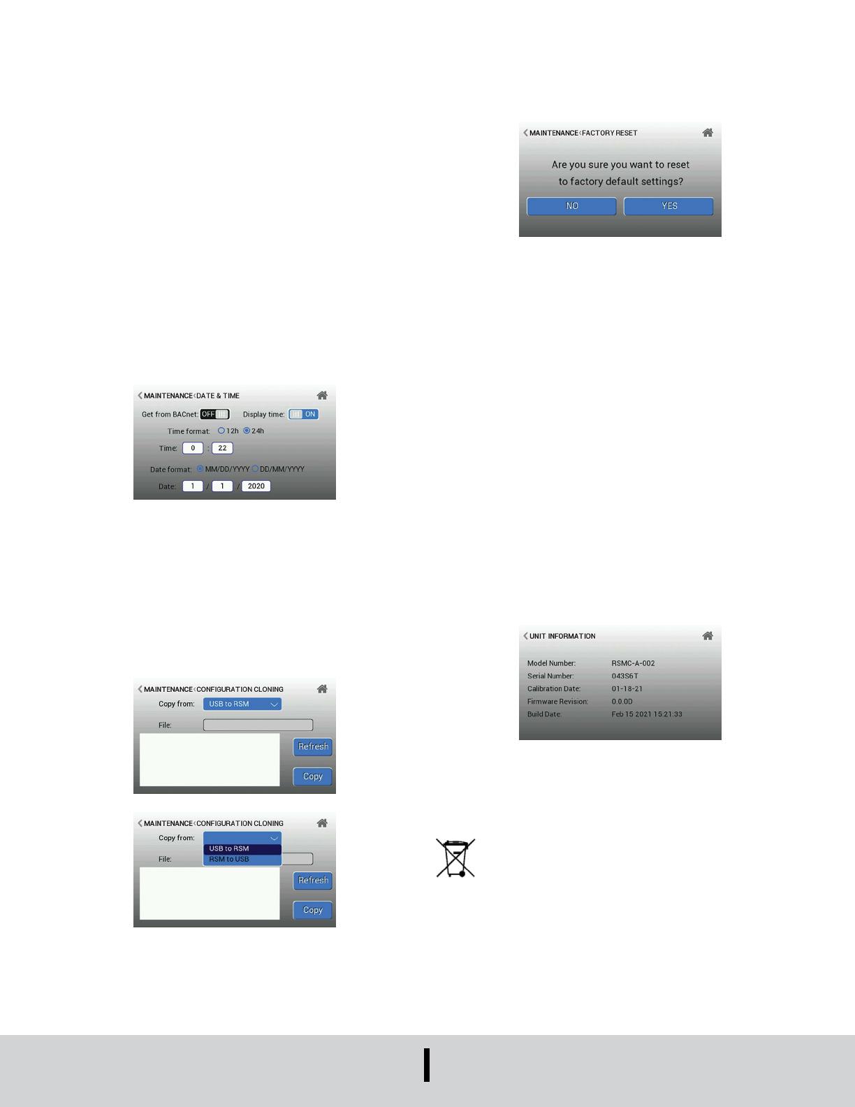
6.2 DATE AND TIME
The Date and Time allows the unit date and time to be manually set, or sourced via
BACnet. The display of the date and time on the home screen can be customized.
Since there is no internal battery, if the power is lost, the date and time will be erased.
If the device is connected by Modbus® or BACnet, the values will be restored via the
network. To access Date and Time from the home screen, press the Settings icon in
the top right corner. From the Maintenance menu, select Date and Time.
6.3 DUPLICATE CLONING
To access Duplicate Cloning from the home screen, press the Settings icon in the
top right corner. From the Maintenance menu, select Duplicate Cloning. The Copy
to USB function is used to capture a RSMC conguration onto a USB thumb drive.
This function is useful to store congurations on a personal computer, where a
controlled inventory of one or more units can be maintained. In the event that a RSMC
password has to be reset or the unit needs replacement, the proper conguration le
can be retrieved and loaded. The Copy from USB function is used to copy a RSMC
conguration from a USB thumb drive to another RSMC unit. A RSMC conguration
previously captured can then be “cloned,” or copied to other units to reduce setup time.
Once copied, the “cloned” unit then only needs room-specic parameters setup, such
as room name, IP address, and other unique parameters.
6.4 RESET TO FACTORY DEFAULTS
The function Reset to Factory Default is used in the event a RSMC unit must be put
into a known state for either service or a conguration reload. To access Reset rom the
home screen, press the Settings icon in the top right corner. From the Maintenance
menu, select Reset.
A factory reset may help establish a baseline of original functionality from which to
build the specic conguration for a given application. New congurations can then
be added by either touchscreen entry, Copy from USB, or over the BACnet network.
Selecting NO will cause the RSMC unit to remain in its current state of conguration.
Selecting YES will cause the RSMC to erase all conguration information and restore
the RSMC to its original factory conguration. Once YES is selected, this function
cannot be reversed or undone.
An alternative way to reset the unit to factory default settings is to insert a paperclip
and press and hold the button located on the back of unit above terminal block pins
4 and 5. The connector for the second terminal block may need to be removed for
easier access. Resetting with the button on the back of the unit will also clear all
passwords established. This resetting method should only be used if the password(s)
are forgotten or lost.
6.5 FIRMWARE UPDATE
To update the device rmware, a USB-C to USB-A drive will be required. Download
the updated device rmware onto the USB drive via a laptop or desktop computer. Do
not change the name of the rmware le, it will end in “.kld”. Once the rmware le
is on the USB-C to USB-A drive, insert the USB-C connection into the back side of
the RSMC unit while it’s powered off. Power on the RSMC with 24 VAC/DC with the
USB drive plugged in. Wait for the device to power on completely. The rmware will be
updated automatically. Once the device has successfully powered on and shows the
homescreen, power off the device and remove the USB drive from the RSMC.
6.6 UNIT INFORMATION
The Unit Information menu displays the model number, serial number, calibration date,
and rmware version. To access the unit information menu, press the Settings icon in
the top right corner of the home screen and select the ‘Unit Information’ button.
MAINTENANCE/REPAIR
Upon nal installation of the Series RSMC, no routine maintenance is required.
The Series RSMC is not eld serviceable and is not possible to repair the unit.
Field repair should not be attempted and may void warranty. Do not dispose of as
unsorted domestic or municipal waste. Consult retailer or local authorities for recycling
information.
WARRANTY/RETURN
Refer to “Terms and Conditions of Sale” in our catalog and on our website. Contact
customer service to receive a Return Materials Authorization number before shipping
the product back for repair. Be sure to include a brief description of the problem plus
any additional application notes.
Modbus® is a registered trademark of Schneider Electric USA, Inc.
This symbol indicates waste electrical products should not be disposed
of with household waste. Please recycle where facilities exist. Check with
your Local Authority or retailer for recycling advice.


