Avaya 4999108476 User manual
- Category
- Telephone switching equipment
- Type
- User manual

IP Telephony
Contact Centers
Mobility
Services
Bedienungsanleitung
Operating instructions
Manual de manejo
Notice d’utilisation
Istruzioni d’uso
Gebruiksaanwijzing
© 2005 All rights reserved for Avaya Inc. and Tenovis GmbH & Co. KG.
4.999.000.000 · 00/00/03 · T3 · de · es · gb · fr · it · nl ·
Avaya-Tenovis GmbH & Co. KG
Kleyerstraße 94
60326 Frankfurt am Main
Telefon 0 800 266 - 10 00
Fax 0 800 266 - 12 19
kundendialog-center
@
avaya.tenovis.com
avaya.tenovis.de
Installation Integral 5 easy
User’s guide


Installation manual Integral 5 D/E easy
06/07
3
4.999.112.593
Copyright ................................................................................. 7
EU-Declaration of Conformity ............................................... 9
CE Declaration of Conformity ..........................................................9
Introduction ........................................................................... 11
Integral 5 D easy ...........................................................................13
Integral 5 E easy ...........................................................................15
Earthing ................................................................................. 17
BNx from below with earthing connections ....................................18
BNx and EXE from below with earthing connections ....................19
Earthing plug ..................................................................................20
Example of earthing using an earthing plug ..................................21
Cable channel ....................................................................... 23
Install the cable channel ................................................................24
Cables .................................................................................... 25
Cables particular to the I5 ..............................................................25
Installation cable ............................................................................29
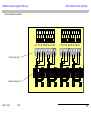
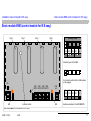
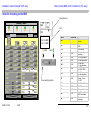
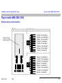
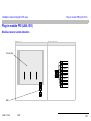
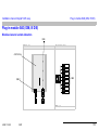
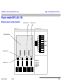
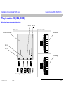
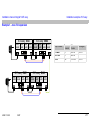
Main distributor frame (20 ports) ........................................ 31
Short description of main distributor frame ...................................33
Patch cables – MDF for further illustrations ...................................34
Connection variants for S0 bus to 2 bus subscribers ....................39
Star S0 bus using MDF ..................................................................43
Power supply ........................................................................ 47
Plug-in mains unit ..........................................................................47
Connection conditions for the plug-in mains unit ...........................48
Wiring ..................................................................................... 51
S0 subscriber – classic S0 wiring ..................................................51
S0 subscriber – point-to-point wiring .............................................53
S0 subscriber – point-to-multiple-point wiring (passive bus) .........54
S0 subscriber –
point-to-multiple-point wiring (extended passive bus) ....................55
S0 subscriber – Y wiring ................................................................56
Analog subscribers / UPN subscribers ..........................................57
Connection T0 to NTBA (TK and MSN) .........................................58
Direct connection (preferred connection option) .....................58
Connection via UAE socket(s)
(required, if distance from NTBA to PABX >10 m) ..................59
Connection PRI to NTPM: .............................................................60
Direct connection (preferred connection option) .....................60
Connection using MDF ............................................................61
Connection RBS to UPD port ........................................................62
Connection using MDF ............................................................62
Basic module BND (control module for I5 D easy) ............ 63
Short description of BND (control module for I5 D easy) ...............64
Allocation of plug-in mains unit and SVin socket on
BND, BNS, BNE, EXE ...................................................................65
Allocation of IOM expander 1 and 2 ..............................................66
Allocation of V.24 Interface ............................................................66
LEDs on the BND ..........................................................................67
Items for mounting on the BND .....................................................68
Items for mounting on the EXE
(Extension of Integral 5 D easy with BND and EXE) .....................69
Basic module BNE (control module for I5 E easy) ............ 71
Short description of BNE ...............................................................72
Allocation of IOM expander 1 thro 4 and LANout ....................73
Items for mounting on the BNE ......................................................74
Items for mounting on the EXE
(Extension of Integral 5 E easy with BNE and EXE) ......................75

06/07
4
4.999.112.593
Installation manual Integral 5 D/E easy
Basic module BNS (slave module for I5 E easy) ............... 77
Short description BNS (slave module) ........................................... 78
Allocation of IOM expander 1 thro 4 and LANin ......................79
Items for mounting on the BNS .....................................................80
Items for mounting on the EXE
(Extension of Integral 5 E easy with BNS and EXE) ..................... 81
Basic module IPU (IP unit) ................................................... 83
Short description of IPU 84
Assignment of LANin, LANout, plug-in mains unit,
SV socket IPU ...............................................................................85
LEDs and DIP switch on the IPU ................................................... 86
LED displays ........................................................................... 87
Dip switch ................................................................................ 88
Basic module EXE (expansion unit for I5 D/E easy) .......... 89
Short description of EXE ...............................................................90
Items for mounting on the EXE, connected to a BND ................... 91
Items for mounting on the EXE, connected to a BNE/BNS ...........93
Assignment of IOM expander L, R and LAN .................................96
DIP switch on the EXE .................................................................. 97
DIP switch on the EXE ............................................................ 98
Plug-in module CV1 (LAN, I5 D/E) ..................................... 101
Module view and socket allocation ..............................................101
Short description CV1 .................................................................102
Further information ...................................................................... 103
Plug-in module DIA (IOM, I5 D/E) ...................................... 105
Module view and socket allocation ..............................................105
Short description of DIA ..............................................................106
Specific features .......................................................................... 107
Plug-in module DSI (IOM, I5 D/E) ....................................... 109
Module view and socket allocation ..............................................109
Short description DSI, DHI, FSP ................................................. 110
Plug-in module M4A (IOM, I5 D/E) .....................................111
Module view and socket allocation .............................................. 111
Short description M4A ................................................................. 112
M4A – subs circuit using MDF .................................................... 114
M4A – exchange circuit using MDF ............................................ 115
Peripherals circuit using MDF ..................................................... 116
Plug-in module MA2 (IOM, I5 D/E) .....................................117
Module view and socket allocation .............................................. 117
Short description of the MA2 ....................................................... 118
MA2 – subscriber circuit using MDF ........................................... 120
Plug-in module MS4 (IOM, I5 D/E) ......................................123
Module view and socket allocation .............................................. 123
Short description of MS4 ............................................................. 124
Connecting MS4 T0/S0 using MDF ............................................. 125
Connecting MS4 T0/S0 using MDF ............................................. 126
I55 <---> I5 connection via QSIG to/via MS4 .............................. 127
PB1 (emergency power supply) ......................................... 129
Module views .............................................................................. 129
Short description PB1 ................................................................. 131
Further information ...................................................................... 132
LED (flashing rhythm / signalling) ............................................... 133
Battery Test ................................................................................. 137
Re-charging Battery .................................................................... 138
Switching off the supply voltage (to BNx or IP module) .............. 139
Battery/accumulator change ....................................................... 139
Plug-in module PRI (LAN, I5 E) ..........................................141
Module view and socket allocation .............................................. 141
Short description PRI ................................................................. 142
Module-specific data ................................................................... 142

Installation manual Integral 5 D/E easy
06/07
5
4.999.112.593
Connection to NTPM using a UAE socket ...................................144
Connection to NTPM using the MDF ...........................................145
IPO <---> I5 connection via QSIG to/via PRI ...............................146
I55 <---> I5 connection via QSIG to/via PRI ................................147
Plug-in module S4A (IOM, I5 D/E) ...................................... 149
Module view and socket allocation ..............................................149
Short description of S4A ..............................................................150
Analog connection using MDF .....................................................151
Plug-in module S4D (IOM, I5 D/E) ...................................... 153
Module view and socket allocation ..............................................153
Short description of S4D ..............................................................154
Summary of the radio ranges ......................................................155
Connecting RBS1 and RBS2 using MDF ....................................156
Connecting RBS1 and RBS2 using MDF ....................................157
Maximum number of DECT units that can be installed
on the system ..............................................................................158
Plug-in module S8D (LAN, I5 E) ......................................... 161
Module view and socket allocation ..............................................161
Short description of S8D ..............................................................162
RBS connection using Y cable ....................................................163
RBS1 thro RBS4 – connection using MDF ..................................164
DECT mounting ...........................................................................166
Plug-in module S8P (LAN, I5 E) ......................................... 169
Module view and socket allocation ..............................................169
Short description of S8P ..............................................................170
Directly connecting UPN subscriber ............................................170
Connecting UPN subs 1 to UPN subs 4
(UPN subs 5 to UPN subs 8) using distributor .............................171
Plug-in module SXS / S4S (IOM, I5 D/E) ............................ 173
Module view and socket allocation ..............................................173
Short description of SXS ..............................................................174
S0 connection using MDF (usual) – 1 ..........................................175
Plug-in module T8S (IOM, I5 D/E) ...................................... 177
Module view and socket allocation ..............................................177
Short description T8S .................................................................178
S0 connection using MDF – 1 ......................................................179
T0 connection using MDF ............................................................181
I55 <---> I5 connection via QSIG to/via T8S ................................183
Plug-in module V.24 ........................................................... 185
Module view and socket allocation ..............................................185
Short description of V.24 .............................................................186
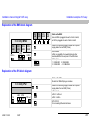
Installation examples I5 D easy ......................................... 187
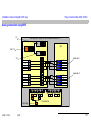
Explanation of the BND block diagram ........................................188
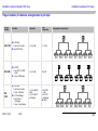
Plug-in modules, B-channels, Arrangements in principle ............190
Example 1 – 1 x BND ..................................................................195
Explanation of example 1 ......................................................195
Example 2 – BND plus EXE - maximum S0 expansion ...............196
Explanation of example 2 ......................................................196
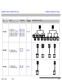
Example 3 – BND plus EXE - maximum UPN expansion ............197
Explanation of example 3 ......................................................197
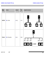
Example 4 – BND plus EXE - maximum analog expansion ........198
Explanation of example 4 ......................................................199
Example 5 – BND plus EXE - maximum DECT expansion .........200
Explanation of example 5 ......................................................201
Installation examples I5 E easy ......................................... 203
Explanation of the BNE block diagram ........................................204
Explanation of the EXE block diagram ........................................204
Explanation of the BNS block diagram ........................................205
Explanation of the IPU block diagram ..........................................205
Plug-in modules, B channels, arrangements in principle .............206

06/07
6
4.999.112.593
Installation manual Integral 5 D/E easy
Example 1 – max. S0 expansion ................................................. 211
Explanation of example 1 ...................................................... 212
Example 2 – max. UPN expansion ..............................................213
Explanation of example 2 ...................................................... 214
Example 3 – max. analog expansion ..........................................216
Example 4 – max. DECT expansion ........................................... 218
Explanation of example 4 ...................................................... 219
Example 5 – mixed expansion (T0, S0, DECT, UPN)) ................221
Explanation of example 5 ...................................................... 222
Example 6 – Expansion with IPU ................................................ 223
Commissioning ................................................................... 225
Check List .................................................................................... 225
Start up the system ..................................................................... 226
Reset ...........................................................................................226
Cold start .....................................................................................227
Switch-on test .............................................................................. 227
Upgrading / reconfiguring modules .............................................228
Extending with EXE, BNS, IPU /
substituting a BNx, EXE, IPU ......................................................230
Technical Data .................................................................... 231
Power supply (plug-in mains unit) ...............................................231
PB1 (converter module) .............................................................. 231
Connection specification for a/b subscriber .................................232
Connection specifications for DECT subscriber .........................232
Connection specification for S0 Telephone .................................233
Connection specification for UPN subscribers ............................233
Dimensions .................................................................................. 234
Heat dissipation ...........................................................................235
Ambient conditions ...................................................................... 235
Transmission Technical Values of the Data Connection .............235
Connection for door station ............................................... 237
Connection for Siedle TLM/TK 511-0 (4-wire)
TLM 611-0 (4-wire) ...................................................................... 237
Grothe door station (4-wire) ........................................................ 239
Connection for Siedle PVG 601 (FTZ 123 D) (2-wire) ................ 241
Connection for telephone-door intercom system /
telephone-interphone porter (Koch) ............................................ 243
Connection for Seko-BTicino,
Sfera door speaker 302120 (4-wire) ........................................... 245
Connection for ELA (4-wire) ........................................................ 247
Potential-free contacts, sensor contact ....................................... 249
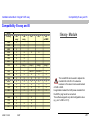
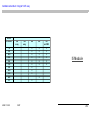
Compatibility I5 easy and I5 ............................................... 251

Installation manual Integral 5 D/E easy Copyright
06/07
7
4.999.112.593
Copyright
© Avaya Inc. and Avaya GmbH & Co. KG, Frankfurt am Main
All rights reserved.
Ref. no: 4.999.112.593
Version: 06 / 07
Reproduction and disclosure of information contained in this document, in whole or in part, require the prior written consent of Avaya GmbH & Co. KG.
All technical data, information and properties of the product described in this document have been compiled to the best of our knowledge at the time printing.
Modifications and improvements to the product are possible because of new technical developments.
Avaya GmbH & Co. KG

06/07
8
4.999.112.593
Installation manual Integral 5 D/E easy Copyright

Installation manual Integral 5 D/E easy EU-Declaration of Conformity
06/07
9
4.999.112.593
EU-Declaration of Conformity
CE Declaration of Conformity
We Avaya GmbH & Co. KG declare that the products I1/I3/I5 (telecommunication systems in various upgrade stages) concur with the basic requirements and
other relevant provisions of EC guideline 1999/5/EC concerning on radio equipment and telecommunications terminal equipment and the mutual recognition
of their conformity.
The telecommunications systems are intended to be connected to analogue 2-wire interfaces (analogue connection) and digital Euro-ISDN interfaces (base
and primary multiplex connection, NTBA or NTPM) of public telecommunication networks within the European Community. The telecommunications systems
support radio interfaces in accordance with the DECT standard. The technical details for connecting to the above named public interfaces can be found in the
system documentation.
Due to the differences in public telecommunication networks of different states and network providers, this EU conformity with the mentioned EU guidelines is
not an absolute guarantee for successful operation in every existing or future telecommunications network.
At present, we are not aware of any public telecommunication network on which this product cannot be operated.
In the event of any problems, please contact your dealer.
The complete Declaration of Conformity can be requested at the following Internet address:
www.avaya.de/gcm/emea/de/includedcontent/conformity.html
or look for „Conformity“ in the index.

06/07
10
4.999.112.593
Installation manual Integral 5 D/E easy EU-Declaration of Conformity

Installation manual Integral 5 D/E easy Introduction
06/07
11
4.999.112.593
Introduction
This document describes the installation of both systems, Integral 5 D easy and Integral 5 E easy. The basis of both these systems id the Integral 5.
Both systems contain a standard client set (basic programming), so that they are immediately functional after switching on.
The special configuration of both systems is achieved by use of the "ISA" tool.
Service and customer data can be edited,
The Integral 5 easy is designed for universal use, e.g.
on site - using the system telephone and input of codes
on site - using a PC (S0, modem, V24)
remotely - using a PC
as a communication system
in the office for self-employed people
in a medical practice for freelancers
in a legal practice for private households
in administration in a hotel
as a central system etc.
as a serial system (key system)

06/07
12
4.999.112.593
Installation manual Integral 5 D/E easy Introduction
This system is driven by software that contains all features described in the "Data Input" handbook.
The system is connected to the exchange by either an ISDN and/or analog connections.
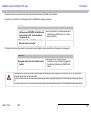
The lines for the internal and external communication network (digital / analog subscribers / exchanges) can be plugged in:
Interfaces:
digital interfaces for operating system
telephones and ISDN/DSS1-compatible end
devices such as PCs, terminal adapters,
fax (group 4), etc.
analog interfaces for standard telephones or
other analog end devices (e.g. fax, modem,
speech recorder).
Ethernet interfaces for IP phones using
Ethernet release 5 or higher
Interfaces:
plugged directly into the individual socket
module
attached to LSA + terminal strips in
the distribution box and thence plugged into
the individual modules using WE-WE patch
cables
A mixed system configuration with direct power supply and emergency power supply (with and without PB1) is not permissible!
The system layout rules can be found under
http://ucpn.intranet.tenovis.com/unternehmen/marketing/tksysteme/integral5/Konfiguration-Datenblatt/Systemaufbauregel-I5D.pdf
and
http://ucpn.intranet.tenovis.com/unternehmen/marketing/tksysteme/integral5/Konfiguration-Datenblatt/Systemaufbauregel-I5E.pdf

Installation manual Integral 5 D/E easy Introduction
06/07
13
4.999.112.593
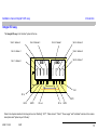
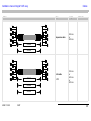
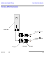
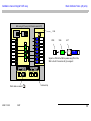
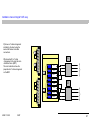
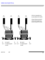
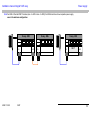
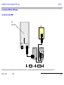
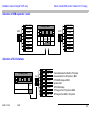
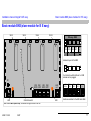
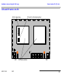
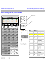
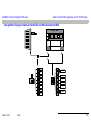
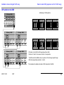
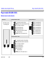
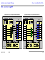
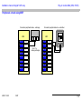
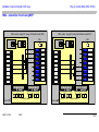
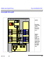
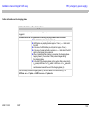
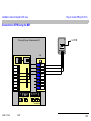
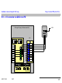
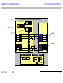
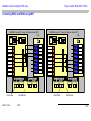
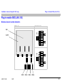
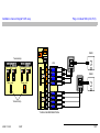
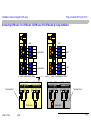
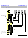
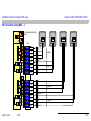
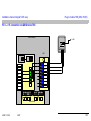
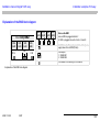
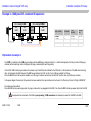
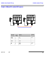
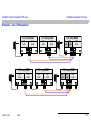
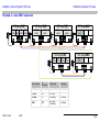
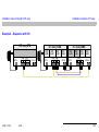
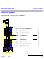
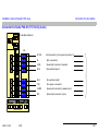
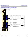
Integral 5 D easy
The Integral 5 D easy is the "smaller" system of the two.
Refer to the chapters identical to the Integral 5 such as "Earthing", "HVT", "Cable channel", "Cable", "Power supply" and "Installation" and also to the module
descriptions and "System layout I5 D easy".
BNDEXE
Slot 2 / Adress 1
Slot 4 / Adress 3
Slot 1 / Adress 0
DC in
Slot 8 / Adress 7
V.24
DC out
Slot 2 / Adress 1
Slot 6 / Adress 5
Slot 4 / Adress 3
Slot 3 / Adress 2
EXPL
EXPR
EXP2
DC in
EXP1

06/07
14
4.999.112.593
Installation manual Integral 5 D/E easy Introduction
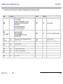
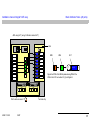
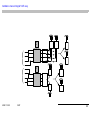
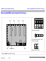
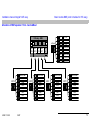
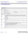
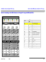
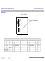
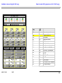
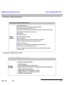
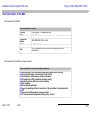
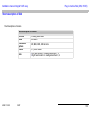
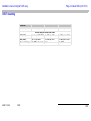
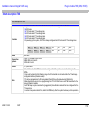
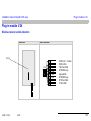
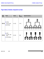
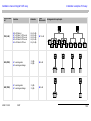
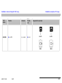
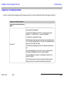
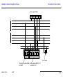
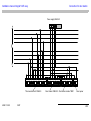
The system layout is modular and can comprise the following basic modules and plug-in modules:
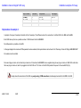
Name LAN/IOM Name LAN/IOM
BND
Basic exchange module
1 x per system
4 slots for IOM/LAN plug-in modules
2 IOM outputs for EXE connections
V24 output
16 internal IOM channels
16 external IOM channels
CV1 LAN Voice controller
EXE
(here on BND)
Extension module EXE
controlled by BND
max. 2 x per system
4 slots for IOM plug-in modules
2 x IOM inputs
T8S LAN 4 x S0 fixed, 4 x S0/T0 switchable
DIA IOM Integral automatic call recording switchboard STN Plug-in mains unit
SXS/S4S IOM 4 x S0 subscribers PB1 Emergency power supply
S4A IOM 4 x a/b subscribers
M4A IOM 3 x a/b lines, 1 x a/b subscriber
S4D IOM 4 x UPN for 2 x DECT-RBS
MA2 IOM 1 x a/b line, 1 x a/b subscriber
DSI IOM 1 x door station (2-wire, 4-wire), 1 x FSP
MS4 IOM 2 x T0, 2 x S0

Installation manual Integral 5 D/E easy Introduction
06/07
15
4.999.112.593
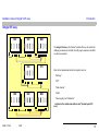
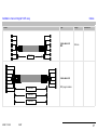
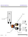
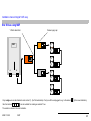
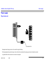
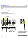
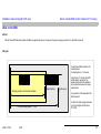
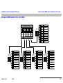
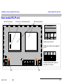
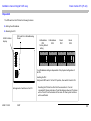
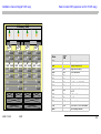
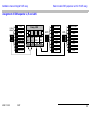
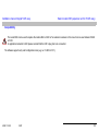
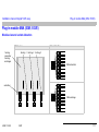
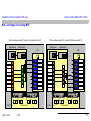
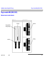
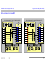
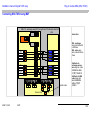
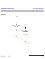
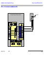
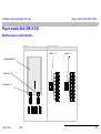
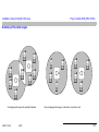
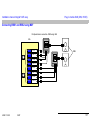
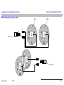
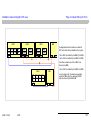
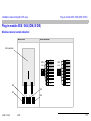
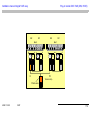
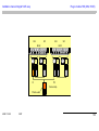
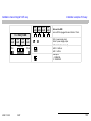
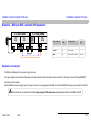
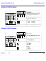
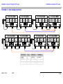
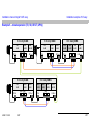
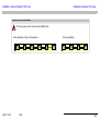
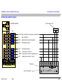
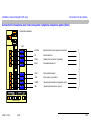
Integral 5 E easy
The Integral 5 E easy is the "smaller" system of the two. As well as the
IOM plug-in modules on the EXE, the LAN plug-in modules on the EXE
can also be used here.
Refer to the chapters identical to the Integral 5 such as
"Earthing",
"HVT",
"Cable channel",
"Cable",
"Power supply" and "Installation"
and also to the module descriptions and "System layout I5 E
easy“.
EXE
EXE EXE BNS
IPU
EXE EXE BNE

06/07
16
4.999.112.593
Installation manual Integral 5 D/E easy Introduction
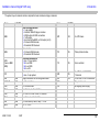
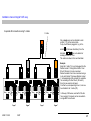
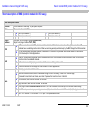
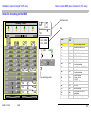
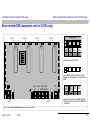
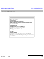
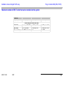
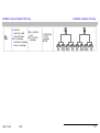
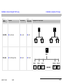
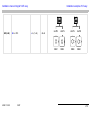
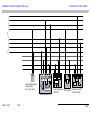
The system layout is modular and can comprise the basic modules and plug-in modules:
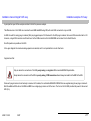
Name LAN/IOM Name LAN/IOM
BNE
Basic exchange module
1 x per system
4 slots for IOM/LAN plug-in modules
4 IOM outputs for EXE connections
1 LAN output
in contrast to the BND, no V24 output (slot 2)
16 internal IOM channels
32 external IOM channels
S8P IOM 8 x UPN 2-wire
BNS
Slave module
16 internal IOM channels
32 external IOM channels
PRI LAN Primary Rate Interface
EXE
(here on BNE/
BNS)
Extension module EXE
max. 12 x per system
4 x on BNE
4 x on BNS
4 x LAN
CV1 LAN Voice controller
IPU
Internet protocol unit
max. 2 x per system
S8D LAN
8 x UPD for 4 x DECT-RBS,
7 channels
DIA IOM Integral automatic call recording switchboard T8S LAN 4 x S0 fixed, 4 x S0/T0 switchable
SXS/S4S IOM 4 x S0 subscribers STN Plug-in mains unit
S4A IOM 4 x a/b subscribers PB1 Emergency power supply
M4A IOM 3 x a/b lines, 1 x a/b subscriber
S4D IOM 4 x UPN for 2 x DECT-RBS - 4 channels
MA2 IOM 1 x a/b line, 1 x a/b subscriber
DSI IOM 1 x door station (2-wire, 4-wire), 1 x FSP
MS4 IOM 2 x T0, 2 x S0

Installation manual Integral 5 D/E easy Earthing
06/07
17
4.999.112.593
Earthing
The PABX Integral 5 easy must be earthed for safety reasons.
Pertinent regulations: DIN EN 60950 "Safety of information technology systems"
The Earthing and Potential Equalisation of the I5 System must comply with relevant national installation regulations.
For instance, for Germany: VDE 800 part 2, or also generally EN 50310.
Earthing is provided
either
using a separate earthing wire (green and yellow) from the potential equalization strip
of the building to the earthing terminal of the BNx module.
Make sure that:
The absolute minimum cross-section of the separately laid protective earths PE
is 2.5 mm
2
, if mechanical protection (e.g.: conductors sheathed in a cable,
in a cable duct or conduit),
otherwise it must be 4 mm
2
or
by a lockable earthing plug (via the earthing wire of the wall socket) (special earthed
plug with cable).

06/07
18
4.999.112.593
Installation manual Integral 5 D/E easy Earthing
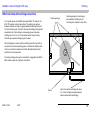
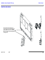
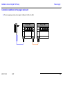
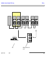
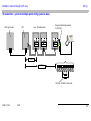
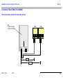
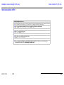
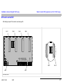
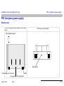
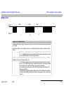
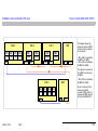
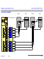
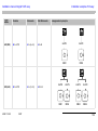
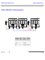
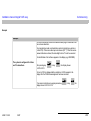
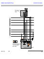
BNx from below with earthing connections
For a system layout with one BNx and several EXE / IP modules, the
EXE / IP modules must also be earthed. The earthing connections
between modules are made using pre-assembled earthing flexes with
4.8 mm Faston tongues. The link to the external earthing point (potential
equalisation rail in the building) is made using a green and yellow
earthing wire of 2.5 or 4 mm² cross-section with a module (screw).
Alternatively a special earthing plug can be used.
When installing, the module with the earthing connection must first be
connected to the external earthing point, to establish an effective earth.
Only then can further modules be installed. Disassembly should be
performed in the reverse order.
No analog exchange line may be connected to / plugged into an MA2 or
M4A module unless the I5 systems are earthed.
Fastening tongue
Fastening tongue for connecting a
pre-assembled earthing flex for
connecting the modules to each other.
And to the external earthing point using:
2,5 / 4 mm² earthing wire (green/yellow)
Special module with earthed plug.
Screw

Installation manual Integral 5 D/E easy Earthing
06/07
19
4.999.112.593
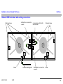
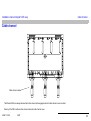
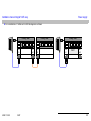
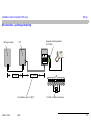
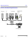
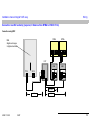
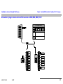
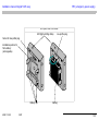
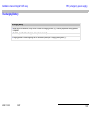
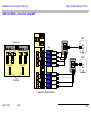
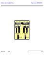
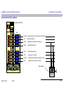
BNx and EXE from below with earthing connections
Fastening tongue Fastening tongueE.g. Common earth for both
BNX and EXE
Earthing flex to connect the
modules
Earthing flex to connect the
modules
Screwto external earthing pointScrew

06/07
20
4.999.112.593
Installation manual Integral 5 D/E easy Earthing
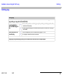
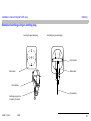
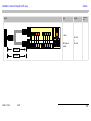
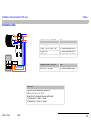
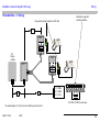
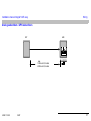
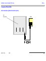
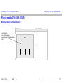
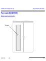
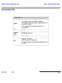
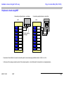
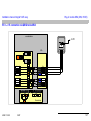
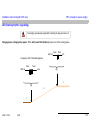
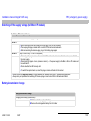
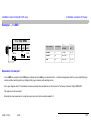
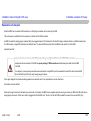
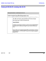
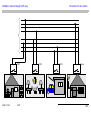
Earthing plug
Earthing plug
Permanent earth for PABX Integral 5 easy via the earth wire of the wall-mounted socket with lockable grounded
plug (earthing-pin plug with cable 49.9804.5750)
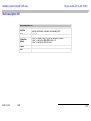
Connecting Earthing
Cable to PABX Integral 5
easy
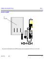
1. Connect the protective conductor (green/yellow) of the grounded plug to the earth
terminal on the module
2. Insert the grounded plug into the wall socket and press in the black bar, the plug is
now locked.
Unlock and remove the
grounded plug
1. Use a screwdriver to pull out the black bar by approx. 10 mm.
2. The plug is unlocked and can be removed
Always plug the grounded plug directly into the wall socket and never into a multiple adapter!
Page is loading ...
Page is loading ...
Page is loading ...
Page is loading ...
Page is loading ...
Page is loading ...
Page is loading ...
Page is loading ...
Page is loading ...
Page is loading ...
Page is loading ...
Page is loading ...
Page is loading ...
Page is loading ...
Page is loading ...
Page is loading ...
Page is loading ...
Page is loading ...
Page is loading ...
Page is loading ...
Page is loading ...
Page is loading ...
Page is loading ...
Page is loading ...
Page is loading ...
Page is loading ...
Page is loading ...
Page is loading ...
Page is loading ...
Page is loading ...
Page is loading ...
Page is loading ...
Page is loading ...
Page is loading ...
Page is loading ...
Page is loading ...
Page is loading ...
Page is loading ...
Page is loading ...
Page is loading ...
Page is loading ...
Page is loading ...
Page is loading ...
Page is loading ...
Page is loading ...
Page is loading ...
Page is loading ...
Page is loading ...
Page is loading ...
Page is loading ...
Page is loading ...
Page is loading ...
Page is loading ...
Page is loading ...
Page is loading ...
Page is loading ...
Page is loading ...
Page is loading ...
Page is loading ...
Page is loading ...
Page is loading ...
Page is loading ...
Page is loading ...
Page is loading ...
Page is loading ...
Page is loading ...
Page is loading ...
Page is loading ...
Page is loading ...
Page is loading ...
Page is loading ...
Page is loading ...
Page is loading ...
Page is loading ...
Page is loading ...
Page is loading ...
Page is loading ...
Page is loading ...
Page is loading ...
Page is loading ...
Page is loading ...
Page is loading ...
Page is loading ...
Page is loading ...
Page is loading ...
Page is loading ...
Page is loading ...
Page is loading ...
Page is loading ...
Page is loading ...
Page is loading ...
Page is loading ...
Page is loading ...
Page is loading ...
Page is loading ...
Page is loading ...
Page is loading ...
Page is loading ...
Page is loading ...
Page is loading ...
Page is loading ...
Page is loading ...
Page is loading ...
Page is loading ...
Page is loading ...
Page is loading ...
Page is loading ...
Page is loading ...
Page is loading ...
Page is loading ...
Page is loading ...
Page is loading ...
Page is loading ...
Page is loading ...
Page is loading ...
Page is loading ...
Page is loading ...
Page is loading ...
Page is loading ...
Page is loading ...
Page is loading ...
Page is loading ...
Page is loading ...
Page is loading ...
Page is loading ...
Page is loading ...
Page is loading ...
Page is loading ...
Page is loading ...
Page is loading ...
Page is loading ...
Page is loading ...
Page is loading ...
Page is loading ...
Page is loading ...
Page is loading ...
Page is loading ...
Page is loading ...
Page is loading ...
Page is loading ...
Page is loading ...
Page is loading ...
Page is loading ...
Page is loading ...
Page is loading ...
Page is loading ...
Page is loading ...
Page is loading ...
Page is loading ...
Page is loading ...
Page is loading ...
Page is loading ...
Page is loading ...
Page is loading ...
Page is loading ...
Page is loading ...
Page is loading ...
Page is loading ...
Page is loading ...
Page is loading ...
Page is loading ...
Page is loading ...
Page is loading ...
Page is loading ...
Page is loading ...
Page is loading ...
Page is loading ...
Page is loading ...
Page is loading ...
Page is loading ...
Page is loading ...
Page is loading ...
Page is loading ...
Page is loading ...
Page is loading ...
Page is loading ...
Page is loading ...
Page is loading ...
Page is loading ...
Page is loading ...
Page is loading ...
Page is loading ...
Page is loading ...
Page is loading ...
Page is loading ...
Page is loading ...
Page is loading ...
Page is loading ...
Page is loading ...
Page is loading ...
Page is loading ...
Page is loading ...
Page is loading ...
Page is loading ...
Page is loading ...
Page is loading ...
Page is loading ...
Page is loading ...
Page is loading ...
Page is loading ...
Page is loading ...
Page is loading ...
Page is loading ...
Page is loading ...
Page is loading ...
Page is loading ...
Page is loading ...
Page is loading ...
Page is loading ...
Page is loading ...
Page is loading ...
Page is loading ...
Page is loading ...
Page is loading ...
Page is loading ...
Page is loading ...
Page is loading ...
Page is loading ...
Page is loading ...
Page is loading ...
Page is loading ...
Page is loading ...
Page is loading ...
Page is loading ...
Page is loading ...
Page is loading ...
Page is loading ...
Page is loading ...
Page is loading ...
Page is loading ...
Page is loading ...
Page is loading ...
Page is loading ...
Page is loading ...
-
 1
1
-
 2
2
-
 3
3
-
 4
4
-
 5
5
-
 6
6
-
 7
7
-
 8
8
-
 9
9
-
 10
10
-
 11
11
-
 12
12
-
 13
13
-
 14
14
-
 15
15
-
 16
16
-
 17
17
-
 18
18
-
 19
19
-
 20
20
-
 21
21
-
 22
22
-
 23
23
-
 24
24
-
 25
25
-
 26
26
-
 27
27
-
 28
28
-
 29
29
-
 30
30
-
 31
31
-
 32
32
-
 33
33
-
 34
34
-
 35
35
-
 36
36
-
 37
37
-
 38
38
-
 39
39
-
 40
40
-
 41
41
-
 42
42
-
 43
43
-
 44
44
-
 45
45
-
 46
46
-
 47
47
-
 48
48
-
 49
49
-
 50
50
-
 51
51
-
 52
52
-
 53
53
-
 54
54
-
 55
55
-
 56
56
-
 57
57
-
 58
58
-
 59
59
-
 60
60
-
 61
61
-
 62
62
-
 63
63
-
 64
64
-
 65
65
-
 66
66
-
 67
67
-
 68
68
-
 69
69
-
 70
70
-
 71
71
-
 72
72
-
 73
73
-
 74
74
-
 75
75
-
 76
76
-
 77
77
-
 78
78
-
 79
79
-
 80
80
-
 81
81
-
 82
82
-
 83
83
-
 84
84
-
 85
85
-
 86
86
-
 87
87
-
 88
88
-
 89
89
-
 90
90
-
 91
91
-
 92
92
-
 93
93
-
 94
94
-
 95
95
-
 96
96
-
 97
97
-
 98
98
-
 99
99
-
 100
100
-
 101
101
-
 102
102
-
 103
103
-
 104
104
-
 105
105
-
 106
106
-
 107
107
-
 108
108
-
 109
109
-
 110
110
-
 111
111
-
 112
112
-
 113
113
-
 114
114
-
 115
115
-
 116
116
-
 117
117
-
 118
118
-
 119
119
-
 120
120
-
 121
121
-
 122
122
-
 123
123
-
 124
124
-
 125
125
-
 126
126
-
 127
127
-
 128
128
-
 129
129
-
 130
130
-
 131
131
-
 132
132
-
 133
133
-
 134
134
-
 135
135
-
 136
136
-
 137
137
-
 138
138
-
 139
139
-
 140
140
-
 141
141
-
 142
142
-
 143
143
-
 144
144
-
 145
145
-
 146
146
-
 147
147
-
 148
148
-
 149
149
-
 150
150
-
 151
151
-
 152
152
-
 153
153
-
 154
154
-
 155
155
-
 156
156
-
 157
157
-
 158
158
-
 159
159
-
 160
160
-
 161
161
-
 162
162
-
 163
163
-
 164
164
-
 165
165
-
 166
166
-
 167
167
-
 168
168
-
 169
169
-
 170
170
-
 171
171
-
 172
172
-
 173
173
-
 174
174
-
 175
175
-
 176
176
-
 177
177
-
 178
178
-
 179
179
-
 180
180
-
 181
181
-
 182
182
-
 183
183
-
 184
184
-
 185
185
-
 186
186
-
 187
187
-
 188
188
-
 189
189
-
 190
190
-
 191
191
-
 192
192
-
 193
193
-
 194
194
-
 195
195
-
 196
196
-
 197
197
-
 198
198
-
 199
199
-
 200
200
-
 201
201
-
 202
202
-
 203
203
-
 204
204
-
 205
205
-
 206
206
-
 207
207
-
 208
208
-
 209
209
-
 210
210
-
 211
211
-
 212
212
-
 213
213
-
 214
214
-
 215
215
-
 216
216
-
 217
217
-
 218
218
-
 219
219
-
 220
220
-
 221
221
-
 222
222
-
 223
223
-
 224
224
-
 225
225
-
 226
226
-
 227
227
-
 228
228
-
 229
229
-
 230
230
-
 231
231
-
 232
232
-
 233
233
-
 234
234
-
 235
235
-
 236
236
-
 237
237
-
 238
238
-
 239
239
-
 240
240
-
 241
241
-
 242
242
-
 243
243
-
 244
244
-
 245
245
-
 246
246
-
 247
247
-
 248
248
-
 249
249
-
 250
250
-
 251
251
-
 252
252
-
 253
253
-
 254
254


Avaya 4999108476 User manual
- Category
- Telephone switching equipment
- Type
- User manual
Ask a question and I''ll find the answer in the document
Finding information in a document is now easier with AI
Other documents
-
Valueline ISDN-0018 Datasheet
-
Sitecom DSI3120 Datasheet
-
Miele RBS 36 User guide
-
CTA Digital WI-NCWD Datasheet
-
Marantec MDF / SA Owner's manual
-
McAfee NTBA T-200 Quick start guide
-
-
-
BRT Systems HVT-Junction User guide
-
Havis-Shields C-VS-700-EXPL User manual