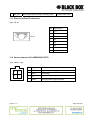
Black Box MDS920C-10BT User manual
- Category
- Routers
- Type
- User manual
This manual is also suitable for

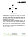
MDS920C-10BT RACK-CARD
MDS921AE-10BT STANDALONE
MDS922AE-10BT MINI-RACK
Ethernet Router / Bridge
User Manual
Version 1.0
Revision 11 February 2003
© Copyright ©2002 by BLACK BOX Network Services AG. The contents of this publication may
not be reproduced in any part or as a whole, transcribed, stored in a retrieval system, translated
into any language, or transmitted in any form or by any means, electronic, mechanical, magnetic,
optical, chemical, photocopying, manual, or otherwise, without the prior written permission of
BLACK BOX Network Services AG. All rights reserved.

VERSION CONTROL.......................................................................................................... 5
1 INTRODUCTION........................................................................................................ 6
3 SPECIFICATIONS ................................FEHLER! TEXTMARKE NICHT DEFINIERT.
4 TECHNOLOGIES....................................................................................................... 9
4.1 xDSL technology, background ..........................................................................9
4.1.1 Asymmetric DSL (ADSL) technology .................................................. 9
4.1.2 ISDN DSL technology ....................................................................... 10
4.1.3 High bit rate DSL (HDSL) technology................................................ 11
4.1.4 EXTRAns technology ........................................................................ 13
4.1.5 Multispeed DSL (MDSL) technology ................................................. 14
4.1.6 Multispeed DSL (MSDSL) technology............................................... 15
4.1.7 G.shdsl technology............................................................................16
4.2 Local area network integration. Access to Internet ......................................... 17
4.2.1 TCP/IP stack structure ...................................................................... 17
4.2.2 Address assignment in IP networks .................................................. 19
4.2.3 Bridging of local networks ................................................................. 21
4.2.4 Routing of networks........................................................................... 25
5 DESCRIPTION OF THE DEVICE ............................................................................ 31
5.1.1 Background ....................................................................................... 31
5.2 Operation mode .............................................................................................. 33
5.2.1 G.shdsl line interface.........................................................................33
5.2.2 Ethernet 10BaseT interface............................................................... 34
5.2.3 ATM interface .................................................................................... 34
5.3 Description of LEDs ........................................................................................ 35
6 MECHANIC DESIGN ............................................................................................... 36
7 EQUIPMENT INSTALLATION.................................................................................41
8 PROGRAMMING GUIDE......................................................................................... 43
8.1 Introduction ..................................................................................................... 43
8.2 Main menu of the bridge mode ....................................................................... 47
8.2.1 Help command .................................................................................. 47
8.2.2 Home command ................................................................................ 47
Version: 1.0 Page. 2 of 95

8.2.3 Default command .............................................................................. 48
8.2.4 Lan command.................................................................................... 48
8.2.5 List command .................................................................................... 49
8.2.6 Manage command............................................................................. 50
8.2.7 Mode command................................................................................. 52
8.2.8 Ping command .................................................................................. 53
8.2.9 Quick command ................................................................................ 53
8.2.10 R1483 command ............................................................................... 54
8.2.11 Restart command .............................................................................. 57
8.2.12 Save command ................................................................................. 57
8.2.13 Shdsl command................................................................................. 58
8.2.14 Show command................................................................................. 62
8.2.15 Ver command .................................................................................... 62
8.3 Main menu of the router mode ........................................................................ 62
8.3.1 Default command .............................................................................. 62
8.3.2 Dnsrelay command ........................................................................... 62
8.3.3 8.3.3 Ipoa command.......................................................................... 64
8.3.4 Lan command.................................................................................... 66
8.3.5 List command .................................................................................... 68
8.3.6 Manage command............................................................................. 68
8.3.7 Mode command................................................................................. 68
8.3.8 Pat command .................................................................................... 68
8.3.9 Ping command .................................................................................. 70
8.3.10 Pppoa command ............................................................................... 70
8.3.11 Pppoe command ............................................................................... 73
8.3.12 R1483 command ............................................................................... 74
8.3.13 Quick command ................................................................................ 76
8.3.14 Restart command .............................................................................. 77
8.3.15 Rtable command ............................................................................... 77
8.3.16 Save command ................................................................................. 78
8.3.17 Shdsl command................................................................................. 78
8.3.18 Show command................................................................................. 78
8.3.19 Ver command .................................................................................... 78
9 FIRMWARE LOADING ............................................................................................79
9.1 Firmware loading guide................................................................................... 79
10 TECHNICAL SPECIFICATIONS ............................................................................. 80
10.1 Interfaces ........................................................................................................ 80
10.1.1 Monitor interface................................................................................ 80
10.1.2 Network management interface ........................................................ 80
Version: 1.0 Page. 3 of 95

10.1.3 SHDSL interface................................................................................ 80
10.1.4 Network interface .............................................................................. 81
10.2 Power supply................................................................................................... 81
10.2.1 Protection against dangerous affects................................................ 82
10.2.2 Surge safety ...................................................................................... 82
10.3 10.3 Climatic conditions .................................................................................. 82
10.4 10.4 Guarantee ............................................................................................... 83
10.5 10.5 Physical dimensions................................................................................ 83
11 CONNECTORS’ DESCRIPTION ............................................................................. 84
11.1 SHDSL connector ........................................................................................... 84
11.2 Monitor connector ........................................................................................... 84
11.3 Ethernet (10BaseT) connector ........................................................................ 85
11.4 Power connector (For MDS922AE-10BT)....................................................... 85
12 DESCRIPTION OF INTERFACE CABLES ............................................................. 86
12.1 «Direct» Ethernet cable................................................................................... 86
12.2 Cross-over Ethernet cable .............................................................................. 87
12.3 Monitor connector ........................................................................................... 87
13 DELIVERY SET ....................................................................................................... 88
14 GLOSSARY .............................................................................................................89
15 EXAMPLE OF NETWORK CONFIGURATION ....................................................... 92
15.1 Router 1 .......................................................................................................... 92
15.2 Router 2 .......................................................................................................... 94
Version: 1.0 Page. 4 of 95

VERSION CONTROL
version Date
Major changes to previous version
0.1 30. Jul. 2001 First version
0.2 9. Sept. 2001 Pre-official version
Chapter 4.2 is changed
Small changes throughout the text
1.0 11. Feb. 2003 Layout, Small changes throughout the text
Version: 1.0 Page. 5 of 95

1 INTRODUCTION
MDS921AE-10BT, MDS920C-10BT and MDS922AE-10BT network and line termination units are
a part of the Black Box PAM family (hereafter family) constructed for the organization of high-
speed communication channels over one pair copper lines (DSL).
This family of units represents G.shdsl modems that have 64 – 2312-kbit/s speed of data transfer.
The modern type of TC-PAM encoding has the best characteristics of long-distance data
transmission and electromagnetic compatibility while working over one pair subscriber lines. TC-
PAM can be deciphered as Trellis Coded Pulse Amplitude Modulation. The essence of this
encoding method consists of an increase of layer numbers (encoding states) from 4 (as in 2B1Q)
to 16 and use of a special error-correction mechanism.
This family of modems with different network interfaces (G.703, Nx64 (V.35/V.36/X.21) and
Ethernet 10Base-T) can be used as transfer systems between multiplexers, routers and cross-
connection devices in different networks, for example:
1. for the organization of E1 (2048 Kbit/s) channels between Public automatic branch
exchange (PABX), Digital Loop Carrier systems, TDM multiplexing and terminal stations
of mobile networks as well as their connection to SDH networks;
2. for the organization of high-speed communication channels (data links) in data transfer
networks and connection of Internet-providers’ access nodes;
3. for the connection of remote working stations (computers) and small Ethernet branches to
the office computer network and for integration of IP and IPX network segments, for
providing Internet access, etc.
The Ethernet 10BaseT interface allows an operator to provide services for the interconnection of
territorially distributed local networks, to provide high-speed access to Internet and to use
MDS921AE-10BT, MDS920C-10BT and MDS922AE-10BT devices in applications that require
high speed data transmission.
The use of ATM technology makes it possible to connect MDS921AE-10BT, MDS920C-10BT and
MDS922AE-10BT units to DSLAM devices of different manufacturers.
The units of this family, subdivided into network termination (NTU) and line termination units
(LTU), can be installed at the customer (user) premises and at the operator (provider) nodes,
respectively. NTU–NTU connections (for instance for the connection of two local networks) or
LTU–LTU connections (for the connection of large nodes) can be used to organize “point-to-
point” connection.
It is possible to power units locally with 48 V
DC
(telephone station batteries) and with 220 V
AC
.
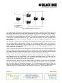
This family of devices has three mechanic designs:
1. Sub-Rack (MDS920C-10BT) is a unit to be mounted in 19’’ chassis (MDS920AE-RMDC)
2. Mini-Rack (MDS922AE-10BT) is a unit of 1U height (44.5 mm) to be mounted in 19’’ rack
cabinet;
3. Stand Alone (MDS921AE-10BT) is a compact unit to be mounted on the tabletop/desktop
or another horizontal surface.
Version: 1.0 Page. 6 of 95

The units have all the possibilities for monitoring and management. Different management
protocols that are used in the firmware of the family allow one to implement:
1. local management using a computer, which supports the VT 100 type emulation of the
terminal;
2. remote monitoring and configuring over Telnet protocol;
3. remote monitoring and configuring over HTTP protocol;
4. support of the CMU SNMP-agent for remote monitoring and configuring while working as
a part of sophisticated networks under Simple Network Management Protocol (SNMP).
The use of Flash-memory chips as read only memory (ROM) facilitates the loading of new
firmware versions.
Version: 1.0 Page. 7 of 95

3 SPECIFICATION
• High-speed symmetric data transfer over a 135-ohm physical twisted copper pair according to
G.shdsl ITU G.991.2;
• TC-PAM line encoding;
• line speed from 72 Kbit/s to 2320 Kbit/s;
• automatic and manual line speed adjusting;
• Ethernet 10Base T interface;
• bridge and router function;
• built-in 4-port HUB on;
• AAL5 for ATM over SHDSL;
• function of traffic priorities;
• DNS support;
• built-in DHCP server;
• NAT support;
• static and dynamic routing, RIP;
• built-in function of diagnostics and self-testing;
• low power consumption;
• console port for local management;
• TELNET and HTTP management;
• built-in SNMP agent;
• possibility of remote firmware loading through TFTP protocol;
• different types of mechanic design.
Version: 1.0 Page. 8 of 95

4 TECHNOLOGIES
4.1 xDSL technology, background
xDSL technology appeared due to the growing user’s demand to high-speed digital stream
transfer over telephone copper pairs. Operators had to organize the interconnection of backbone
stations of cellular networks, Digital Loop Carrier systems, interstation connection and to provide
high-speed Internet access at minimal expenses. In these circumstances, it was reasonable to
use the existing telephone cables. The new technology acquired the name – xDSL (Digital
Subscriber Line).
“x” key
x is a variable in the DSL technology, where every word has its own meaning. Thus the term
“Digital” means, that not an analogue but digital signal, that was processed by one of line
encoding methods, is transmitted over pairs. In fact, the term xDSL points at this or that line code
the distance of data transfer and maximal connection speed depend on it. However, some
technologies, for example ADSL, can use one of the two line codes: either Discrete Multi-Tone
(DMT) or Carrierless Amplitude/Phase (CAP).
The term “Subscriber Line” is referred to physical copper pairs of telephone cable, or in simple
words, to “direct wires”. The term DSL was originally referred to the ISDN technology, but later
was borrowed by the developers of xDSL technologies.
4.1.1 Asymmetric DSL (ADSL) technology
The most popular DSL technology, ADSL, was developed in Bellcore laboratory in late 1980s.
Standards Institutes assigned the use of carrier set modulation, which acquired the name DMT,
to ADSL, while another leading method received the name of Rate-Adaptive DSL (RADSL).
ADSL transmits downstream to the end user and upstream to the net. The ADSL technology
does not use 25–30-kHz frequencies, used for a subscriber’s access to public switched telephone
network (PSTN). This provides simultaneous subscriber’s access to data transfer networks and
PSTN over the same copper pair. The original ADSL implies the presence of splitters both on
LTU and NTU. However, ADSL without splitters found its use and acquired the name of ADSL
Lite or G.lite. Later, it was standardized by ITU-T. This standard supports downstream speeds up
to 1.5 Mbit/s and upstream speeds up to 512 Kbit/s.
4.1.1.1 ADSL in brief
Standard
• G.lite G.992.1 (G.DMT)
• T1 413-1998
• Interoperability between equipment of different manufacturers
Version: 1.0 Page. 9 of 95

Transmission rate
• Downstream
• up to 6–8 Mbit/s
• up to 1.5 Mbit/s for G.lite
• Upstream
• up to 640 Kbit/s
• up to 512 Kbit/s for G.lite
Line code
• DMT
• CAP
Number of pairs
• one pair
Usage
• public network operators (PNO) and Internet service providers
Restrictions
• Asymmetry
4.1.2 ISDN DSL technology
The IDSL technology is based on the ISDN technology, but without switching. IDSL uses 2B1Q
line encoding and has two B and one D channel capacity, which allows transmitting data bi-
directional at 144 Kbit/s. The necessity to transmit simultaneously voice and data served as a
powerful spur to the further development of IDSL. Thus, the channel capacity is divided between
voice unit and digital interface. NTU-128 Voice is an example of a device implementing this
mode,
Version: 1.0 Page. 10 of 95

4.1.2.1 IDSL in brief
Standard
• T1.601
• interoperability between equipment of different manufacturers at the U interface layer
Transmission rate
• up to 144 Kbit/s
• up to 64 Kbit/s + voice channel in NTU-128 Voice
Line code
• 2B1Q
Transmission medium
• one pair
• possibility of the regenerator’s installation
Usage
• PNOs and providers of Internet services
• commercial operators
• integration of LANs
Restrictions
• low speed
• impossibility of transmission rate adjusting
4.1.3 High bit rate DSL (HDSL) technology
The HDSL technology allows transmitting synchronous digital data at 1.54- or 2.048-Mbit/s speed
over two copper pairs. This standard was accepted by European Telecommunication Standards
Institute. 2B1Q or CAP 64 are used as line codes. The data transmission rate over each pair is
1168 Kbit/s, the decrease of linear rate is not provided. The 2B1Q encoding HDSL technology
allows to connect up to 3 remotely powered regenerators.
Version: 1.0 Page. 11 of 95

4.1.3.1 HDSL in brief
Standard
• ETSI TS 101 135
• interoperability between equipment of different manufacturers is not provided
Transmission rate
• 1168 Kbit/s over each pair (2 Mbps over two pairs)
Line code
• 2B1Q
• CAP 64
Transmission medium
• two pairs
• possibility of the regenerator’s installation (up to 3)
Usage
• PNOs
• long-haul E1 transmission
• organization of trunk lines between PABX
• increase of capacity of subscribers’ lines with the help of Digital Loop Carrier systems
• high-speed access to SDH networks
Restrictions
• two pairs are used for stream transmission
• impossibility to regulate transmission rates
• increased influence on analog systems with frequency division multiplexing/demultiplexing
Version: 1.0 Page. 12 of 95

4.1.4 EXTRAns technology
xDSL solutions are widely used for the organization of interstation trunk lines, creation of routes
for multiplexers and routers. But the wide spread of analog systems with frequency division
multiplexing/demultiplexing of the K-60, K-24, K-12 types makes it difficult to use standard xDSL
solutions over backbone (trunk lines)
and zone cables of the different types with the wire
diameter of 0.9–1.2, if one of the analog systems works over cables. To digitalize local and zone
lines, NTC NATEKS engineered the EXTRAns technology based on asymmetric adaptive
multimode CAP modulation with a regulated level. This technology allows transmitting
synchronous digital stream with a changeable line speed from 144 to 2064 Kbit/s over two copper
pairs. The technology stipulates the installation of up to 6 remotely powered regenerators. The
number of regenerators can be doubled if they are remotely powered from two-manned repeater
station, where power source is available.
4.1.4.1 EXTRAns in brief
Standard
• Patent № 2001104235/20(004956) of the Federal Institute of Industrial Property
• interoperability with the equipment of other manufacturers is not provided
Transmission rate
• 144–2064 Kbit/s
Line code
• CAP-EXTRAns
Transmission medium
• two pairs
• possibility of the regenerator’s installation (up to 6)
Usage
• PNOs, Competitive Local Exchange Carriers (CLECs)
• creation of long-haul digital routes with many regenerating segments
• organization of trunk lines between PABX
• increase of capacity of subscribers’ lines with the help of Digital Loop Carrier systems
Version: 1.0 Page. 13 of 95

• high-speed access to SDH networks
Restrictions
• two pairs are used for full stream transmission
4.1.5 Multispeed DSL (MDSL) technology
The term SDSL was used for several years on the market. It was referred to all solutions meant
for the synchronous digital stream transmission over one pair. This technology supports the
possibility of line speed regulation over long-haul distances. The technology is implemented in
MDSL and MSDSL, the latter one having a different line code. The MDSL technology uses 2B1Q
line code. The transmission rate varies from 144 to 2320 Kbit/s. Regenerators are not used here.
4.1.5.1 MDSL in brief
Standard
• ETSI TS 101 135
• interoperability between equipment of different manufacturers at the level of DSL chips
Transmission rate
• 144–2320 Kbit/s
Line code
• 2B1Q
Transmission medium
• one pair
• impossibility of the regenerator’s installation
Usage
• Internet service providers
• access to Internet
• integration of LANs
Version: 1.0 Page. 14 of 95

Restrictions
• the shortest distance of data transfer over one wire compared to other technologies
4.1.6 Multispeed DSL (MSDSL) technology
The MSDSL technology is a further development of the MDSL technology. It allows to run over
longer distances because of using a more progressive line code – CAP. In addition, it is possible
to install a CAP-splitter, which allows using the copper pair for both data transfer and telephoning
connection. The technology supports the installation of a line regenerator. However, the spectral
characteristics of the CAP code interfere with other xDSL systems, running over the neighboring
pairs in the same cable. The ADSL technology is exposed to the greatest influence.
4.1.6.1 MSDSL, in brief
Standard
• ETSI TS 101 135
• interoperability between equipment of different manufacturers is not provided
Transmission rate
• 144–2064 Kbit/s
Straight-line code
• CAP8…CAP128
4.1.6.2 Transmission medium
• one pair
• one regenerator
Usage
• PNOs, Internet service providers
• access to Internet
• integration of LANs
Version: 1.0 Page. 15 of 95

• creation of trunk lines between PABX
• increase of capacity of subscribers’ lines with the help of Digital Loop Carrier systems
• high-speed access to SDH networks
Restrictions
• absence of compatibility with the equipment of other manufacturers
• interference with other xDSL services
4.1.7 G.shdsl technology
The G.shdsl technology was engineered as a universal technology of synchronous digital data
transmission. It became an international standard for symmetric systems. The technology
supports the transmission over one and two pairs. Special stress, while developing the
technology, was laid to provide spectral compatibility with other technologies such as ADSL,
IDSL, MDSL, MSDSL.
4.1.7.1 G.shdsl, in brief
Standard
• ITU-T G.991.2
• compatibility with the equipment of other manufacturers
Transmission rate
• 192–2360 Kbit/s
Line code
• TC-PAM
Transmission medium
• one or two pairs
• possible installation of up to three regenerators
Usage
• PNOs, Internet service providers
Version: 1.0 Page. 16 of 95

• access to Internet
• integration of LANs
• creation of trunk lines between PABX
• increase of subscribers’ lines with the help of Digital Loop Carrier systems
• high-speed access to SDH networks
4.2 Local area network integration. Access to Internet
Local area networks facilitate documentation-processing, access to data in modern companies
but the Ethernet technology does not allow to transfer data at long distances and create Wide
Area Networks (WANs). xDSL can be used for the solution of this problem.
4.2.1 TCP/IP stack structure
TCP/IP became widely practiced with the development of the Internet all over the world. It was
engineered earlier than the OSI model, and that is why differs greatly.
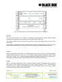
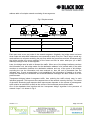
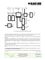
Fig.1 shows the TCP/IP structure.
TCP/IP protocols are composed of 4 layers:
Layer IV
The lowest layer (Layer IV) corresponds to the physical and data link layers of the OSI reference
model. This layer in TCP/IP is not regulated, but it supports all the popular physical and data link
layer standards: for LANs, this is Ethernet, for WANs, these are Point-to-Point Protocols, SLIP,
Frame Relay. However, when a new LAN and WAN technology appears, it is usually included
into TCP/IP stack because of a specially engineered request for comments (RFC), which
determines the encapsulation method of IP packets into its frames. Thus, for the encapsulation of
IP protocols into ATM cells, there was engineered a special RFC 1483 method. This method is
used in Black Box PAM modems as well.
Version: 1.0 Page. 17 of 95

Fig.1 Correspondence of TCP/IP layers with the OSI model layers
Layer III
The next layer (Layer III) is a layer of internetwork interconnection, which enables packet
transmission using different transmission media, LANs, WANs, xDSL, etc.
The Internet Protocol is used as the primary protocol of this layer (session layer in terms of the
OSI model).
All protocols, connected with data collecting and updating of routing tables, such as Routing
Internet Protocol (RIP) refer to this layer. This protocol is used in Black Box PAM modems.
Layer II
Layer II is sometimes called basic. The Transmission Control Protocol (TCP) and User Datagram
Protocol (UDP) function at this level. TCP provides reliable packet transmission using virtual
links. UDP, as well as IP, enables datagram application packet transmission. It functions as a
connecting link between network protocols and numerous application processes.
Layer I
Layer I is called the application layer. It contains a great number of application layer protocols
and services. Such widely used protocols as File Transfer Protocol (FTP), Telnet terminal
emulation protocol, Simple Network-Management Protocol (SNMP) (used in the e-mail), WWW
protocols and many others belong to this layer.
Version: 1.0 Page. 18 of 95

4.2.2 Address assignment in IP networks
Any IP-network device is characterized by the addresses of three groups:
Physical address. It is a hexadecimal MAC address of the network adapter or port. The MAC
address is unique and is 6-byte long: the first 3 bytes are the manufacturer’s identifier and the
other 3 bytes are uniquely assigned by the manufacturer itself. For example, 18-B7-34-39-AA-FC.
Network address (IP address). It is assigned during the configuring of network devices by the
administrator and does not depend on the physical address. The address has a decimal
representation and its length is 4 bytes. It consists of two parts: network number and node
number. Depending on the class of the network, different quantity of bytes is assigned to the
network number..
IP address classes
The network address consists of two logical parts: network and node number. The values of the
first address bits mean what part of the address refers to the network number and what to the
node number:
• Class A networks. The network number takes one byte, the other three show the node number
in the network. Class A networks can only have numbers in the 1.0.0.0–126.0.0.0 range.
Networks with number are not used, and number 127 is reserved. The node count must be more
than 126 but less than 224. The first bit of the network address of Class A must start with 0.
• Class B networks. The network and node numbers take two bytes each. Class B networks can
have numbers in the 128.0.0.0–191.255.0.0 range. The node count must be more than 28 but
less than 216. The network address of Class B must have the first two bits equal to 10.
• Class C networks. The network number takes three bytes. Class C networks can have numbers
in the 192.0.1.0–223.255.225.0 range. The node count must no be more than 28. The network
address of Class C must have the first three bits equal to 110.
• Class D networks. The networks of this class have a special multicast address. Class D
networks can have numbers in the 224.0.0.0–239.255.225.225 range. All nodes that have this
address will receive a packet with an address that belongs to Class D network. The network
address of Class D must begin with a sequence of 1110.
• Class E networks. The networks of this class are not used and they are reserved for future
(experimental) usage. Class E networks can have numbers in the 240.0.1.0–247.255.225.225
range. The network address of Class E must begin with a sequence of 11110.
Version: 1.0 Page. 19 of 95

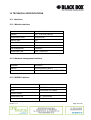
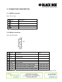
4 bytes
1 2 3 4
Class А
0 Network № Node №
Class B
1 0 Network № Node №
Class C
1 1 0 Network № Node №
Class D
1 1 1 0 Multicast address
Class E
1 1 1 1 0 Reserved
Masks
Network mask is a number, consisting of four bytes. It is a decimal number divided by dots, and it
is used together with the IP address. A mask usually contains decimal numbers – 255. The use of
masks allows providing users with narrow address ranges compared to networks of different
classes. The least dedicated range without masks is Class C network, i.e. 256 addresses. Using
masks, the entry 192.168.1.253 mask 255.255.255.252 defines the address 192.168.1.253 in the
subnet of four-address range: from 192.168.1.252 to 192.168.1.255.
4.2.2.1 Automatic assignment of IP addresses
The administrator can assign IP addresses to network devices either manually or automatically. If
there are many devices in the network, the address assignment is a long and painstaking
process. Dynamic Host Configuration Protocol (DHCP) was developed to facilitate this process.
The primary task of DHCP is dynamic IP address assignment. However, besides dynamic, DHCP
can support simpler means of manual and automatic statistic address assignment.
The administrator takes active part during the manual procedure of address assignment. He
presents information about correspondence of IP addresses to MAC addresses or other
customer’s identifiers to DHCP server.
During the automatic-static address assignment, the DHCP server assigns a free IP address from
the IP address range without reference to the administrator. The administrator gives the
boundaries of the address range during the DHCP-server configuration. In this case, the IP
address remains the same all the time.
During the dynamic address assignment, the DHCP server assigns an address to the customer
for a limited period of time. It means that later other computers can reuse the IP address.
Version: 1.0 Page. 20 of 95
Page is loading ...
Page is loading ...
Page is loading ...
Page is loading ...
Page is loading ...
Page is loading ...
Page is loading ...
Page is loading ...
Page is loading ...
Page is loading ...
Page is loading ...
Page is loading ...
Page is loading ...
Page is loading ...
Page is loading ...
Page is loading ...
Page is loading ...
Page is loading ...
Page is loading ...
Page is loading ...
Page is loading ...
Page is loading ...
Page is loading ...
Page is loading ...
Page is loading ...
Page is loading ...
Page is loading ...
Page is loading ...
Page is loading ...
Page is loading ...
Page is loading ...
Page is loading ...
Page is loading ...
Page is loading ...
Page is loading ...
Page is loading ...
Page is loading ...
Page is loading ...
Page is loading ...
Page is loading ...
Page is loading ...
Page is loading ...
Page is loading ...
Page is loading ...
Page is loading ...
Page is loading ...
Page is loading ...
Page is loading ...
Page is loading ...
Page is loading ...
Page is loading ...
Page is loading ...
Page is loading ...
Page is loading ...
Page is loading ...
Page is loading ...
Page is loading ...
Page is loading ...
Page is loading ...
Page is loading ...
Page is loading ...
Page is loading ...
Page is loading ...
Page is loading ...
Page is loading ...
Page is loading ...
Page is loading ...
Page is loading ...
Page is loading ...
Page is loading ...
Page is loading ...
Page is loading ...
Page is loading ...
Page is loading ...
Page is loading ...
-
 1
1
-
 2
2
-
 3
3
-
 4
4
-
 5
5
-
 6
6
-
 7
7
-
 8
8
-
 9
9
-
 10
10
-
 11
11
-
 12
12
-
 13
13
-
 14
14
-
 15
15
-
 16
16
-
 17
17
-
 18
18
-
 19
19
-
 20
20
-
 21
21
-
 22
22
-
 23
23
-
 24
24
-
 25
25
-
 26
26
-
 27
27
-
 28
28
-
 29
29
-
 30
30
-
 31
31
-
 32
32
-
 33
33
-
 34
34
-
 35
35
-
 36
36
-
 37
37
-
 38
38
-
 39
39
-
 40
40
-
 41
41
-
 42
42
-
 43
43
-
 44
44
-
 45
45
-
 46
46
-
 47
47
-
 48
48
-
 49
49
-
 50
50
-
 51
51
-
 52
52
-
 53
53
-
 54
54
-
 55
55
-
 56
56
-
 57
57
-
 58
58
-
 59
59
-
 60
60
-
 61
61
-
 62
62
-
 63
63
-
 64
64
-
 65
65
-
 66
66
-
 67
67
-
 68
68
-
 69
69
-
 70
70
-
 71
71
-
 72
72
-
 73
73
-
 74
74
-
 75
75
-
 76
76
-
 77
77
-
 78
78
-
 79
79
-
 80
80
-
 81
81
-
 82
82
-
 83
83
-
 84
84
-
 85
85
-
 86
86
-
 87
87
-
 88
88
-
 89
89
-
 90
90
-
 91
91
-
 92
92
-
 93
93
-
 94
94
-
 95
95


Black Box MDS920C-10BT User manual
- Category
- Routers
- Type
- User manual
- This manual is also suitable for
Ask a question and I''ll find the answer in the document
Finding information in a document is now easier with AI
Related papers
Other documents
-
 Corecess 3311N User manual
-
 XAVI Technologies Corp. X7868r User manual
-
Telewell TW-EA800 User manual
-
IBM Heritage User manual
-
 Heritage Kayaks HERITAGE series User manual
-
-
 Data Connect 5201A-MR-P Owner's manual
-
CTC Union SHDSL User manual
-
D-Link DSL-1500G User manual
-
Patton 3086FR User manual


