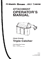
Simplicity 1694918 is a grass catcher designed for use with Simplicity lawn tractors. It has a triple-bag design that provides ample capacity for collecting grass clippings, leaves, and other debris. The catcher is easy to install and remove, and it features a durable construction that ensures long-lasting performance.
Here are some of the key features and benefits of the Simplicity 1694918 grass catcher:
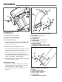
- Triple-bag design for increased capacity
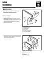
- Easy to install and remove
- Durable construction for long-lasting performance
- Helps to keep your lawn looking neat and tidy
Simplicity 1694918 is a grass catcher designed for use with Simplicity lawn tractors. It has a triple-bag design that provides ample capacity for collecting grass clippings, leaves, and other debris. The catcher is easy to install and remove, and it features a durable construction that ensures long-lasting performance.
Here are some of the key features and benefits of the Simplicity 1694918 grass catcher:
- Triple-bag design for increased capacity
- Easy to install and remove
- Durable construction for long-lasting performance
- Helps to keep your lawn looking neat and tidy


-
 1
1
-
 2
2
-
 3
3
-
 4
4
-
 5
5
-
 6
6
-
 7
7
-
 8
8
-
 9
9
-
 10
10
-
 11
11
-
 12
12
-
 13
13
-
 14
14
-
 15
15
-
 16
16


Simplicity 1694918 is a grass catcher designed for use with Simplicity lawn tractors. It has a triple-bag design that provides ample capacity for collecting grass clippings, leaves, and other debris. The catcher is easy to install and remove, and it features a durable construction that ensures long-lasting performance.
Here are some of the key features and benefits of the Simplicity 1694918 grass catcher:
- Triple-bag design for increased capacity
- Easy to install and remove
- Durable construction for long-lasting performance
- Helps to keep your lawn looking neat and tidy
Ask a question and I''ll find the answer in the document
Finding information in a document is now easier with AI
Related papers
-
Simplicity TRIPLE CATCHER User manual
-
-
-
-
-
-
Simplicity 1694499 User manual
-
-
-
Snapper 1694498 User manual
Other documents
-
-
-
-
Briggs & Stratton 1695354 User manual
-
-
Toro 72" Front Baffle Kit, For Groundsmaster 200 Series Installation guide
-
-
-
-