Page is loading ...
Page is loading ...

3
en GET TO KNOW YOUR APPLIANCE
fr PRÉSENTATION DE VOTRE APPAREIL
de LERNEN SIE IHR GERÄT KENNEN
it CONOSCERE L'APPARECCHIO
pt CONHEÇA O SEU APARELHO
es CONOZCA SU EQUIPO

4
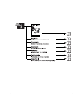
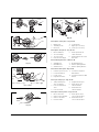
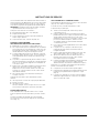
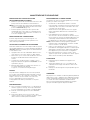
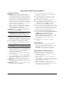
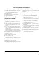
Description of the parts
* Depending on the model
Description des pièces
* Selon le modèle
Beschreibung der Teile
* Je nach Ausführung
Descrizione delle parti
* A seconda della versione
Descrição das peças
* De acordo com o modelo
Descripción de las partes
*Según la versión
1. Engine 11. Handle bar
2. Tank cap 12. EZ-Link™
3. Starter handle 13. Shaft
4. Spark plug 14. Cutting attachment cover
5. Choke lever * 15. Line blade
6. Intake pump 16. Cutting attachment
7. Air filter/muffler cover 17. Blade with cover
8. Shoulder belt holder 18. Shoulder belt
9. Ignition switch 19. Limiter Sleeve
10. Throttle
1. Moteur 11. Guidon
2. Bouchon du réservoir 12. Lien EZ™
3. Poignée du lanceur 13. Manche
4. Bougie 14. Couvercle de l'accessoire
5. Manette de starter * de coupe
6. Pompe aspirante 15.Lame coupe-fil
7. Filtre à air / Couvercle 16. Accessoire de coupe
de silencieux 17. Lame de coupe
8. Fixation de la bandoulière avec couvercle
9. Interrupteur d'allumage 18. Bandoulière
10. Manette des gaz 19. Manchon du limiteur
1. Motor 11. Griffstange
2. Tankverschluss 12. EZ-Link™
3. Startergriff 13. Schaft
4. Zündkerze 14. Schneidaufsatz-
5. Chokehebel * abdeckung
6. Ansaugpumpe 15. Fadenschneidklinge
7. Luftfilter/Schalldämpfer- 16. Schneidaufsatz
Abdeckung 17. Schneidklinge
8. Schulterriemenhalterung mit Abdeckung
9. Zündschalter 18. Schulterriemen
10. Gashebel 19.Abstandsmanschette
1. Motore 11.Manubrio
2. Tappo del serbatoio 12. Giunto EZ-Link™
3. Impugnatura 13.Asta
di avviamento 14. Copertura dell'attrezzo
4. Candela di accensione a fili di nylon
5. Levetta farfalla aria * 15.Lama per il taglio del filo
6. Pompa di aspirazione 16.Attrezzo di taglio
7. Coperchio filtro aria/ a fili di nylo
silenziatore di scarico 17.Lama di taglio
8. Fissaggio della tracolla con coperchio
9. Interruttore di accensione 18.Tracolla
10. Leva acceleratore 19.Manicotto di limitazione
1. Motor 9.Interruptor de ignição
2. Tampa do depósito 10.Alavanca de aceleração
3. Puxador do cabo 11. Barra de punhos
de arranque de orientação
4. Vela de ignição 12.EZ-Link™
5. Alavanca do 13.Haste
estrangulador (CHOKE) * 14.Cobertura do adaptador
6. Bomba de aspiração de corte
7. Cobertura do filtro de ar/ 15. Fio de corte
silenciador acústico 16.Adaptador de corte
(escape) 17. Lâmina de corte
8. Dispositivo de fixação com cobertura
da cinta de transporte 18.Cinta de transporte
ao ombro ao ombro
19.Saia limitadora
1. Motor 11.Barra manija
2. Cierre del tanque 12.Link EZ™
3. Manija de arranque 13.Vástago
4. Bujía 14.Cobertura del cabezal
5. Palanca del cebador * de corte
6. Bomba de aspiración 15.Cuchilla para el hilo
7. Cobertura del filtro 16. Cabezal de corte
de aire y del silenciador 17.Hoja de la cuchilla
8. Soporte de la correa con cobertura
para colgar en el hombro 18.Correa para colgar
9. Llave de encendido en el hombro
10. Palanca del acelerador 19.Manguito limitador

5
Fig. 1
Fig. 2
Fig. 3
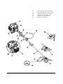
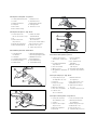
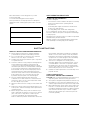
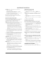
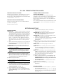
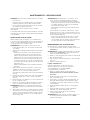
Description of the parts – Fig. 1–4
Description des pièces – Fig. 1–4
Beschreibung der Teile – Abb. 1–4
Descrizione delle parti – Fig. 1–4
Descrição das peças – Fig. 1–4
Descripción de las partes – Fig. 1 a 4
Fig. 4
Fig. 5 Fig. 6
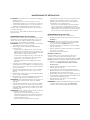
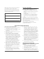
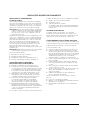
1. Handle bar 5. Lower clamp
2. Screw 6. Nut
3. Upper clamp 7. Quick-release lock
4. Middle clamp
1. Guidon 5. Bride inférieur
2. Vis 6. Écrou
3. Bride supérieure 7. Fermeture rapide
4. Bride médiane
1. Griffstange 5.Untere Klemme
2. Schraube 6.Mutter
3. Obere Klemme 7.Schnellverschluss
4. Mittlere Klemme
1. Manubrio 5.Morsetto inferiore
2. Vite 6.Dado
3. Morsetto superiore 7. Arresto rapido
4. Morsetto intermedio
1. Barra de retenção 5.Braçadeira inferior
2. Parafuso 6.Porca
3. Braçadeira superior 7.Fecho rápido
4. Braçadeira média
1. Barra manija 5.Grapa inferior
2. Tornillo 6. Tuerca
3. Grapa superior 7.Cierre rápido
4. Grapa central
7
7

6
Fig. 7
Fig. 8
Fig. 9
Depending on the model –
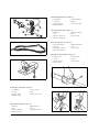
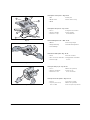
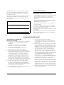
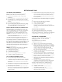
Description of the parts – Fig. 7–9
Selon le modèle –
Description des pièces – Fig. 7–9
Je nach Ausführung –
Beschreibung der Teile – Abb. 7–9
A seconda della versione –
Descrizione delle parti – Fig. 7–9
De acordo com o modelo –
Descrição das peças – Fig. 7–9
Según la versión –
Descripción de las partes – Fig. 7 a 9
1
2
4
3
7
2
6
1
5
3
1. EZ-Link™ 5.Main hole
2. Release button 6.Upper shaft tube
3. Button 7.Lower shaft tube
4. Guide groove
1. Lien EZ™ 4. Rainure de guidage
2. Bouton 5.Trou principal
de déclenchement 6.Tube d'arbre supérieur
3. Bouton 7.Tube d'arbre inférieur
1. EZ-Link™ 5.Hauptloch
2. Auslöseknopf 6.oberes Wellenrohr
3. Knopf 7.unteres Wellenrohr
4. Führungsrille
1. Giunto EZ-Link™ 5. Foro principale
2. Pulsante di sgancio 6.Tubo dell'albero superiore
3. Manopola 7. Tubo dell'albero inferiore
4. Gola di guida
1. EZ-link™ 5.Furo principal
2. Botão de accionamento 6.Tubo ondulado superior
3. Botão 7.Tubo ondulado inferior
4. Fenda de guia
1. Link EZ™ 5.Orificio principal
2. Botón de traba 6.Tubo superior del eje
3. Botón 7.Tubo inferior de eje
4. Ranura guía

7
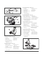
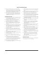
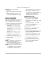
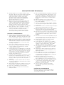
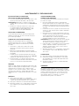
Description of the parts – Fig. 10–13
Description des pièces – Fig. 10–13
Beschreibung der Teile – Abb. 10–13
Fig. 10
Fig. 11
Fig. 12
Fig. 13
Descrizione delle parti– Fig. 10–13
Descrição das peças – Fig. 10–13
Descripción de las partes – Fig. 10 a 13
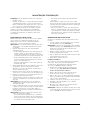
1. Cutting attachment plate 7. Safety bar slot
2. Screws 8. Shaft bush hole
3. Guard attachment 9. Cutting attachment
4. Safety bar 10. Cutting holder
5. Drive shaft 11. Protective cover
6. Drive shaft housing
1. Tôle de protection 6. Carter de l'arbre
de l'accessoire de coupe d'entraînement
2. Vis 7. Fente pour tringle
3. Fixation de la tôle de sécurisation
de protection 8. Trou pour douille d'arbre
4. Tringle de sécurisation 9. Accessoire de coupe
5. Arbre d'entraînement 10. Fixation de coupe
11. Capot de protection
1. Schneidaufsatz- 6. Antriebswellengehäuse
schutzblech 7. Sicherungsstangenschlitz
2. Schrauben 8.Wellenbuchsenloch
3. Schutzblechbefestigung 9. Schneidaufsatz
4. Sicherungsstange 10. Schneidhalterung
5. Antriebswelle 11. Schutzabdeckung
3
1
2
4
7
8
6
5
1. Lamiera di protezione 7. Fessura dell'asta
dell'attrezzo a fili di nylon di sicurezza
2. Viti 8.Foro nella bussola
3. Fissaggio della lamiera dell'albero
di protezione 9.Attrezzo di taglio
4. Asta di sicurezza a fili di nylon
5. Albero motore 10. Fissaggio lama di taglio
6. Alloggiamento dell'albero 11. Coperchio di protezione
motore
1. Chapa de protecção 7.Ranhura da barra
do adaptador de corte de segurança
2. Parafusos 8.Furo da bucha do veio
3. Fixação da chapa 9.Adaptador de corte
de protecção 10. Dispositivo de fixação
4. Barra de segurança do corte
5. Veio de accionamento 11. Cobertura de protecção
6. Caixa do veio
de accionamento
1. Chapa de cobertura 6.Carcasa del eje motriz
del cabezal de corte 7. Ranura para la barra
2. Tornillos de seguridad
3. Sujeción de la chapa 8.Orificio buje para el eje
de protección 9. Cabezal de corte
4. Barra de seguridad 10. Soporte de corte
5. Eje motriz 11. Cobertura de protección
4
9
R
E
W
I
N
D
L
I
N
E
R
E
W
I
N
D
L
I
N
E
10
11
Page is loading ...

9
Fig. 17
Fig. 18
Fig. 19
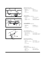
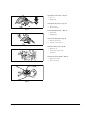
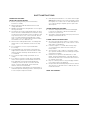
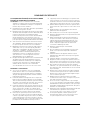
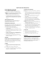
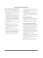
Description of the parts – Fig. 17–19
* Depending on the model
Description des pièces – Fig. 17–19
* Selon le modèle
Beschreibung der Teile – Abb. 17–19
* Je nach Ausführung
Descrizione delle parti – Fig. 17–19
* A seconda della versione
Descrição das peças – Fig. 17–19
* De acordo com o modelo
Descripción de las partes – Fig. 17 a 19
*Según la versión
Fig. 20
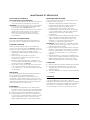
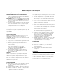
1. Throttle 6. Operating position (3) *
2. Throttle lock 7. Choke lever *
3. Ignition switch 8. Intake pump
4. Full choke position (1 *) 9. Starter rope
5. Half choke intermediate
position (2) *
1. Manette des gaz 5. Starter en position
2. Cran d'arrêt de la manette médiane (2) *
des gaz 6. Position de service (3) *
3. Interrupteur d'allumage 7.Manette de starter *
4. Starter en position (1) * 8.Pompe d'aspiration
9. Cordon du lanceur
4
7
5
8
6
1. Gashebel 6.Betriebsposition (3) *
2. Gashebelsperre 7.Chokehebel *
3. Zündschalter 8. Ansaugpumpe
4. volle Chokeposition (1) * 9. Starterseil
5. halbe Choke
Zwischenposition (2) *
1. Leva acceleratore 6.Posizione di
2. Blocco leva acceleratore funzionamento (3) *
3. Interruttore di accensione 7. Levetta della farfalla aria *
4.
Farfalla aria tutta aperta (1) *
8.Pompa di aspirazione
5. Farfalla aria aperta a metà 9.Fune di avviamento
posizione intemedia (2) *
1. Alavanca de aceleração 5.Posição intermédia
2. Bloqueio da alavanca do estrangulador (2) *
de aceleração 6. Posição de
3. Interruptor de ignição funcionamento (3) *
4. Posição do estrangulador 7.
Alavanca do estrangulador *
fechado (1) * 8. Bomba de aspiração
9.Cabo de arranque
1. Palanca del acelerador 6. Posición de
2. Bloqueo de acelerador funcionamiento (3) *
3. Llave de encendido 7. Palanca del cebador *
4. Posición máxima 8.Bomba de aspiración
para el cebador (1) * 9.Cuerda de arranque
5. Posición central para
el cebador (2) *

10
Fig. 21
Fig. 22
Fig. 23
Fig. 24
Description of the parts – Fig. 24
Description des pièces – Fig. 24
Beschreibung der Teile – Abb. 24
Descrizione delle parti – Fig. 24
Descrição das peças – Fig. 24
Descripción de las partes – Fig. 24
R
E
W
I
N
D
L
I
N
E
R
E
W
I
N
D
L
I
N
E
1. Line coil
2. Bump knob
1. Bobine de fil
2. Bouton débiteur
1. Fadenspule
2. Auftippknopf
1. Bobina a fili di nylon
2. Pulsante a percussione
1. Bobina do fio
2. Tampa de bloqueio do fio
da bobina
1. Bobina para el hilo
2. Botón de asiento

11
Fig. 25
Fig. 26
Fig. 27
Fig. 28
Fig. 29
Fig. 30
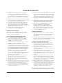
Description of the parts – Fig. 25–30
Description des pièces – Fig. 25–30
Beschreibung der Teile – Abb. 25–30
Descrizione delle parti – Fig. 25–30
Descrição das peças – Fig. 25–30
Descripción de las partes – Fig. 25 a 30
R
E
W
I
N
D
L
I
N
E
R
E
W
I
N
D
L
I
N
E
R
E
W
I
N
D
L
I
N
E
R
E
W
I
N
D
L
I
N
E
L
I
N
E
W
I
T
H
a)
b)
c)
1
R
E
W
I
N
D
L
I
N
E
R
E
W
I
N
D
L
I
N
E
3
3
2
R
E
W
I
N
D
L
I
N
E
R
E
W
I
N
D
L
I
N
E
L
R
E
W
I
N
D
L
I
N
E
R
E
W
I
N
D
L
I
N
E
R
E
W
I
N
D
L
I
N
E
R
E
W
I
N
D
L
I
N
E
L
1
L
2
L
1
L
1
L
1
L
2
L
2
L
2
=
b)
a)
W
I
T
H
E
Y
E
L
E
T
R
E
W
I
N
D
L
I
N
E
R
E
W
I
N
D
L
I
N
E
L
I
N
E
U
P
S
L
O
T
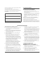
1. Bump knob 4. Locking plate
2. Threading holes 5. Upper spool housing
3. Exit holes 6. Lower spool housing
1. Bouton débiteur 5. Partie supérieure du
2. Trous d'enfilage carter de bobine
3. Trous de sortie 6. Partie inférieure du carter
4. Patte de verrouillage de bobine
1. Auftippknopf 4. Arretierungslasche
2. Einfädellöcher 5. Oberes Spulengehäuse
3. Austrittslöcher 6. Unteres Spulengehäuse
1. Pulsante a percussione 5. Contenitore superiore
2. Fori d'introduzione della bobina
3. Fori di uscita 6. Contenitore inferiore della
4. Linguetta di arresto bobina
1. Tampa de bloqueio 4. Lingueta de retenção
do fio da bobina 5. Parte superior da
2. Furos de enfiamento caixa da bobina
do fio 6. Parte inferior da
3. Furos de saída caixa da bobina
1. Botón de asiento 5. Parte superior de la
2. Orificios para enhebrar carcasa de la bobina
3. Orificios de salida 6. Parte inferior de la
4. Eclisa de traba carcasa de la bobina
a) b)
c)
5
6
4

12
Fig. 31
Fig. 32
Description of the parts – Fig. 31–32
* Depending on the model
Description des pièces – Fig. 31–32
* Selon le modèle
Beschreibung der Teile – Abb. 31–32
* Je nach Ausführung
Descrizione delle parti – Fig. 31–32
* A seconda della versione
Descrição das peças – Fig. 31–32
* De acordo com o modelo
Descripción de las parte – Fig. 31 a 32
*Según la versión
Fig. 33 Fig. 34
Fig. 35
Fig. 36
Fig. 37
Description of the parts – Fig. 36–37
Description des pièces – Fig. 36–37
Beschreibung der Teile – Abb. 36–37
Descrizione delle parti – Fig. 36–37
Descrição das peças – Fig. 36–37
Descripción de las partes – Fig. 36 a 37
1. Choke lever * 3. Air filter
2. Screw
1. Manette de starter * 3.Filtre à air
2. Vis
1. Chokehebel * 3. Luftfilter
2. Schraube
1. Levetta della farfalla aria * 3. Filtro aria
2. Vite
1. Alavanca do 2. Parafuso
estrangulador de ar * 3.Filtro de ar
1. Palanca del cebador * 3. Filtro de aire
2. Tornillo
2
2
1
2
2
1
3
1. No load speed governor 2.Spark plug
1. Régulateur de vitesse 2.Bougie
de marche à vide
1. Leerlaufdrehzahlregler 2. Zündkerze
1. Regolatore del numero 2. Candela di accensione
di giri al minimo
1. Regulador de rotações 2. Vela de ignição
em ponto morto
1. Regulador de 2.Bujía
marcha en vacío
1
0,63 mm
2
0,63 mm
2

13
Enter all information on the rating plate of your unit
in the following field.
You can find the rating plate near the engine.
These specifications are very important for subsequent
identification when ordering spare parts and for customer
service.
SAFE OPERATING PRACTICES
USING THE UNIT CORRECTLY
This unit is designed
– to be used in accordance with the descriptions and safety
instructions indicated in this operating manual
– for private use
– for trimming lawn edges and small inaccessible areas
of grass (e.g. under bushes)
– for cutting wild growth, shrubs and undergrowth.
It is not permitted to use this unit for any other purposes.
The user is liable for all injuries to third parties and damage
to their property.
Operate the unit only in the technical condition as stipulated
and delivered by the manufacturer.
Arbitrary changes to the unit will exclude the manufacturer
from any liability for resulting injury and/or damage.
SAFETY INSTRUCTIONS
READ ALL INSTRUCTIONS BEFORE OPERATING
Please read these instructions carefully. Familiarize
yourself with the operation and handling of the unit.
Do not use this unit if you are tired or ill or under the
influence of alcohol, drugs or medication.
Children and young people under 16 years of age must
not operate the unit.
Check the unit before using it. Replace damaged parts.
Check whether fuel is leaking out. Ensure that all
connections are attached and tight. Replace cutting
attachment parts which are cracked, flawed or damaged
in any other way and that the cutting attachment has
been installed correctly and secured properly. Ensure
that the guard for the cutting attachment has been
attached correctly and is in the recommended position.
If these instructions are not followed, the user and
bystanders may be injured or the unit damaged.
Use only original replacement lines which have
a diameter of 2.41 mm. Never use a metal-reinforced
string, wire, chain, rope, etc. These may break off and
become dangerous projectiles.
Always be aware of the risk of injury to head, hands and
feet.
Depress the throttle. It must automatically return to the
home position. Perform all settings and/or repairs before
operating the unit.
Before using the unit, always clear the area which you
want to trim. Remove all objects such as stones, broken
glass, nails, wire or string which could be ejected
or become entangled in the cutting attachment.
Remove children, bystanders and animals from the area.
Keep children, bystanders and animals at a minimum
distance of 15 m; there is always a risk of bystanders
being hit by ejected objects. Bystanders should wear
eye protection. If somebody approaches, immediately
switch off the engine and cutting attachment.
This unit is not designed to be used by persons
(including children) who have limited physical, sensory
or mental abilities or who have no experience and/or
knowledge of the unit, unless they are supervised by
a person responsible for their safety or they have been
instructed by the person how to use the unit.
Children should be supervised to ensure that they do not
play with the unit.
SAFETY INSTRUCTIONS
FOR PETROL-DRIVEN LAWN TRIMMERS
CAUTION: Petrol is highly flammable and the vapours may
explode if ignited. Take the following precautions:
Store petrol in designated and permitted containers only.
Keep ignition sources away from spilled petrol. Do not
start the engine until the petrol vapours have evaporated.
Before filling the tank, always switch off the engine and
leave it to cool down. Never remove the tank cap and
never fill the tank while the engine is hot. Before using the
unit, ensure that the tank cap is screwed on tightly.
Slowly unscrew the tank cap to reduce the pressure
in the tank gradually.

14
SAFETY INSTRUCTIONS
Mix petrol and fill the tank in a clean, well ventilated
outdoor area only where there are no sparks or flames.
After switching off the engine, slowly unscrew the tank
cap. Do not smoke while mixing petrol or filling the tank.
Immediately wipe any spilled petrol off the unit.
Before switching on the engine, carry the unit at least
10 m away from the filling station. While filling the tank
or using the unit, do not smoke and keep sparks and
naked flames out of the area.
OPERATING THE UNIT
Never start the unit and never leave it running in a closed
room or building. The inhalation of exhaust gases may
be fatal. Use the unit outdoors only.
Wear eye and ear protection when using the unit.
If working in a dusty environment, wear a face or dust
mask. A long-sleeved shirt is recommended.
Wear thick, long trousers , boots and gloves. Do not
wear loose clothing, jewellery, short trousers, sandals
and do not walk barefoot. Pin your hair above your
shoulders.
The cutting attachment guard must always be attached
when the unit is being used as a lawn trimmer. Both trim
lines must be pulled out and the correct line must
be installed. The trim line must not be pulled out over
the end of the guard.
The unit has a clutch. The cutting attachment stops
when the unit is running at no load. If it does not stop,
have the unit adjusted by a mechanic at your authorised
dealer.
Before switching on the unit, ensure that the line spool/
cutting blade cannot strike an object.
Adjust the handle bar to your height so that the you have
the unit under control.
Do not touch the cutting attachment on the unit.
Operate the unit in daylight or adequate artificial lighting
only.
Avoid starting the unit unintentionally. Be ready
to operate the unit when you pull the starter rope.
User and unit must be in a stable position when the unit
is started. See Fig. 19 and the Start/Stop instructions.
Use this unit for its designated purpose only.
Do not stretch too far over the unit. Always have a secure
footing and keep your balance.
When operating the unit, always hold the unit firmly with
both hands. Always hold both sides of the handle bar
firmly.
When operating the unit, always wear the shoulder belt.
Keep your hands, face and feet away from all
moving parts. Do not touch the cutting attachment
while it is rotating and do not attempt to stop it.
Do not touch the engine or muffler. These parts become
very hot while the unit is being used. They remain hot for
a short time even when the unit is switched off.
Do not let the engine run quicker than required for cutting
or trimming of lawn edges. Do not run the engine at high
speed when it is not cutting.
Always switch off the engine if you cannot start cutting
immediately or if you are moving from one place
to another.
If you strike or ensnare a foreign object, immediately
switch off the engine and check whether the unit has
been damaged. Never use the unit with loose
or damaged parts.
Stop and switch off the engine for maintenance, repairs
or when changing the cutting attachment or other
attachments.
Use only original spare parts for repairs. These parts can
be purchased from your authorised dealer.
Never use parts, accessories or attachments which are
not authorised for this unit. Otherwise, the user may
be seriously injured and the unit damaged. In addition,
your warranty may be deemed null and void.
Keep the unit clean and ensure that there are no plants
or other objects caught between the cutting attachment
and guard.
To reduce the risk of fire, please replace damaged
mufflers and spark extinguishers and remove grass,
leaves, excess lubricants and layers of soot from the
engine and muffler.
Have all repairs carried out by a repair shop only.
OPERATING TIMES
Observe the national/municipal regulations concerning times
of use (if required, ask your local authority).

15
SAFETY INSTRUCTIONS
OPERATING THE UNIT
WITH THE CUTTING BLADE
Before operating the unit, please read all safety
instructions carefully.
Always keep the handle bar between the user and
cutting attachment.
NEVER cut material if the cutting blade is 75 cm or higher
above ground level.
The unit may recoil if the rotating blade strikes an object
which cannot be cut immediately. Recoils may be strong
enough to throw the unit and/or user in any direction and
may cause the user to lose control of the unit. Recoils
may occur without warning if the blade gets caught,
jams or locks. This can easily happen in areas in which
the material to be cut is difficult to see.
Never use the undergrowth blade to cut undergrowth
thicker than 12.7 mm. Otherwise, violent recoils may
occur.
Do not attempt to touch or stop the blade while
it is rotating.
A rotating blade may cause injuries, even when the
engine has been switched off or the throttle has been
released. Hold the unit firmly until the blade has come
to a standstill.
Do not run the engine at high speed when it is not
cutting.
If you strike or ensnare a foreign object, immediately
switch off the engine and check whether the unit has
been damaged. Have the repair damaged before
continuing to use the unit. Do not use the unit with
a bent, cracked or blunt blade. Throw away bent,
twisted, cracked or broken blades.
Do not sharpen the cutting blade. The sharpened tip of
the blade may break off during operation. This may result
in serious injuries. Replace the blade.
If extremely violent vibrations occur, switch off the engine
IMMEDIATELY. Vibrations are a sign of problems. Check
thoroughly for loose bolts, nuts or other damage before
you continue cutting. If required, repair or replace the
affected parts.
AFTER OPERATING THE UNIT
Clean the cutting blades with a household detergent
to remove any remnants. Lubricate the blade with
machine oil to prevent rust.
Store and lock away the blade securely to protect it from
damage and unauthorised use.
OTHER SAFETY INSTRUCTIONS
As long as the tank still has petrol in it, never store the
unit in a building where vapours could come into contact
with sparks or naked flames.
Leave the engine to cool down before transporting
or conveying the unit. Attach the unit securely for
transportation.
Store the unit in a dry condition, locked away or high
up to prevent unauthorised use and damage. Keep the
unit away from children.
Never douse or splash the unit with water or other
liquids. Keep the handle bar dry, clean and dust-free.
Clean the unit after each use and follow the instructions
for cleaning and storage.
Dispose of waste petrol/oil or any packaging remnants
in accordance with local regulations.
Keep this manual. Read it frequently and use it to instruct
other users. If you lend this unit to somebody else, also
include this manual.
KEEP THIS MANUAL.

16
SAFETY INSTRUCTIONS
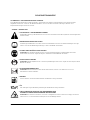
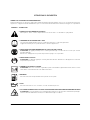
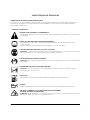
SAFETY AND INTERNATIONAL SYMBOLS
This operating manual describes safety and international symbols and pictograms which may be displayed on this unit. Read this
user handbook in order to familiarise yourself with all safety, installation, operating and repair instructions.
SYMBOL MEANING
SAFETY AND WARNING SYMBOL
Indicates danger, warning or a reason to be cautious. Can be used together with other symbols or pictograms.
READ OPERATING MANUAL
Non-compliance with the operating instructions and precautions may result in serious injuries.
Read the operating manual before starting or operating the unit.
WEAR EYE AND EAR PROTECTION
CAUTION: Ejected objects may cause serious eye injuries and excess noise may cause loss of hearing.
When operating the unit, wear eye and ear protection.
WEAR HEAD PROTECTION
CAUTION: Falling objects may cause serious head injuries. When operating the unit, wear head protection.
KEEP BYSTANDERS AWAY
CAUTION: All bystanders, especially children and pets, must be kept at least 15 m from the working area.
PETROL
Always use clean and fresh lead-free petrol for mixing petrol.
OIL
Use only authorised oil according to the operating manual for mixing petrol.
EJECTED OBJECTS AND ROTATING PARTS MAY CAUSE SERIOUS INJURIES
CAUTION: Do not use the unit if the protective housing has not been correctly positioned for cutting.
Keep away from the rotating line coil and cutting blade.

17
SAFETY INSTRUCTIONS
SYMBOL MEANING
IGNITION SWITCH
ON / START / RUN
IGNITION SWITCH
OFF or STOP
BEWARE OF HOT SURFACES
Do not touch hot muffler cover, gearbox or cylinder. You could burn yourself.
These parts become extremely hot while the unit is being used. They remain hot for a short time even
when the unit is switched off.
SHARP BLADE
CAUTION: Sharp blade on the guard as well as sharp cutting blade. To prevent serious injuries,
do no touch the blade.
CHOKE SETTINGS
1 • FULL CHOKE start position.
2 • HALF CHOKE intermediate position.
3 • Operating position.
MAXIMUM RPM
Do not let the unit run more quickly than the maximum rpm.
WEAR FOOT AND HAND PROTECTION
While operating this unit, wear heavy duty boots and protective gloves.
DO NOT FILL UP WITH FUEL OF SPECIFICATION E85
If fuel of specification E85 (ethanol content >15 %) is used, the engine may be damaged.
The use of an unauthorised fuel will void the warranty.

18
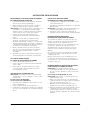
INSTALLATION MANUAL
INSTALLING AND SETTING THE HANDLE BAR
1. Position the handle bar between the upper and middle
clamp (Fig. 1).
2. Hold the three parts together and screw the four (4) bolts
through the upper clamp into the middle clamp.
NOTE: The holes in the upper and middle clamps will not
be in alignment unless the clamps have been installed
correctly.
3. Hold the clamps and the handle bar over the shaft
housing and on the lower clamp.
4. Hold each of the hex nuts in the lower clamp recess with
one finger. Loosely screw in the bolts with a large cross-
head screwdriver. Do not tighten the screws until the
handle bar has been set correctly.
5. Hold the unit in the operating position (Fig. 20) and
position the handle bar until you have a secure footing.
6. Evenly tighten the bolts in the holder until the handle bar
is secure.
ATTACHING AND ADJUSTING
THE SHOULDER BELT
1. Pull the belt through the buckle (Fig. 3).
2. Pull the shoulder belt over your head and place the pad
on your shoulder.
3. Latch the hook of the shoulder belt into the metal holder
(Fig. 4). Adjust the belt to a comfortable length.
USING THE EZ-LINK
TM
SYSTEM
NOTE: To facilitate installation and removal of attachments,
place the unit on the ground or a workbench.
Removing the cutting attachment
or other attachments
1. To loosen the attachment, rotate the screw handle to the
left (Fig. 7).
2. Press and hold down the release button (Fig. 7).
3. Hold the upper shaft housing securely and pull the
cutting attachment or other attachment directly out
of the EZ-Link
TM
coupling (Fig. 8).
INSTALLING THE CUTTING ATTACHMENT OR
OTHER ATTACHMENTS
1. To loosen the attachment, rotate the screw handle to the
left (Fig. 7).
2. Hold the attachment securely and push directly into the
EZ-Link
TM
coupling (Fig. 8).
NOTE: Alignment of the release button with the guide groove
facilitates installation (Fig. 7).
3. Secure the attachment by rotating the button to the right
(Fig. 9). Before operating the unit, ensure that the rotary
handle is secure.
REMOVING AND INSTALLING
THE CUTTING ATTACHMENT GUARD
If the unit is used for cutting undergrowth (with cutting blade),
remove the cutting attachment guard.
Remove the cutting attachment guard from the guard holder
by unscrewing the three (3) screws with a flat screwdriver
(Fig. 10). Keep parts for subsequent use.
If the unit is used as a lawn trimmer, install the guard for the
cutting attachment.
Install the cutting attachment guard in the guard holder
by screwing in the three (3) screws with a flat screwdriver.
Tighten the screws (Fig. 10).
REMOVING THE CUTTING ATTACHMENT
AND ATTACHING THE CUTTING BLADE
NOTE: To facilitate removal or installation of the cutting blade
or the cutting attachment, place the unit on the ground
or a workbench.
Removing the cutting attachment
NOTE: First attach the guard to the cutting blade.
1. Align the shaft bush hole with the slot for the safety bar
and guide the safety bar into the shaft bush hole (Fig. 11).
2. Hold the safety bar in place by gripping it together with
the shaft of the unit (Fig. 12).
3. While holding the safety bar, remove the cutting
attachment by screwing it clockwise off the drive shaft
(Fig. 13). Keep the cutting attachment for subsequent
use.

19
INSTALLATION MANUAL
Installing the cutting blade
4. Remove the cutting attachment guard. See Removing
and installing the cutting attachment guard.
5. Place the cutting blade on the drive shaft (Fig. 14).
6. Centre the cutting blade on the drive shaft housing
(Fig. 14).
7. Ensure that the cutting blade is centred and is situated
flat against the drive shaft housing.
8. Align the shaft bush hole with the slot for the safety bar
and guide the safety bar into the shaft bush hole (Fig. 11).
9. Attach the blade holder and nut to the drive shaft
(Fig. 14). Check that the blade has been installed
properly.
10. While holding the safety bar, tighten the nut anti-
clockwise (Fig. 15). – Tightening torque 37 Nm –.
If you do not have a torque wrench, turn the nut against
the blade holder until it is situated firmly on the shaft
bush. Check that the blade has been installed properly
and then turn the nut anti-clockwise a further ¼ to ½ turn
(Fig. 15).
11. Remove the safety bar from the safety bar slot.
12. Remove the guard from the cutting blade.
REMOVING THE CUTTING BLADE AND
INSTALLING THE CUTTING ATTACHMENT
Removing the cutting blade
1. Attach the guard to the cutting blade.
2. Align the shaft bush hole with the slot for the safety bar
and guide the safety bar into the shaft bush hole (Fig. 11).
3. Hold the safety bar in place by gripping it together with
the shaft of the unit (Fig. 12).
4. While holding the safety bar, loosen the nut on the blade
by turning it clockwise with a screw key or socket
wrench (Fig. 16).
5. Remove the nut, blade holder and blade. Keep the nut
and blade together in a secure location for subsequent
use. Keep them out of the reach of children.
Installing the cutting attachment
6. Align the shaft bush hole with the slot for the safety bar
and guide the safety bar into the shaft bush hole (Fig. 11).
Place the blade holder on the drive shaft with the flat
surface against the drive shaft housing (Fig. 13). Rotate
the cutting attachment anti-clockwise onto the drive
shaft. Tighten firmly.
NOTE: The blade holder must be installed on the drive
shaft in the illustrated position, otherwise the cutting
attachment will not function properly.
7. Remove the safety bar.
8. Install the cutting attachment guard. See Removing
and installing the cutting attachment guard.

20
OIL AND FUEL RECOMMENDATIONS
RECOMMENDED OIL GRADE
Use quality oil only, API classification TC (TSC-3) which
is offered for air-cooled two-stroke engines. Mix the oil
for two-stroke engines according to the instructions
on the container, 1:40 (2.5%).
RECOMMENDED PETROL GRADE
Always use clean, fresh lead-free petrol
(maximum 60 days old).
Minimum octane number: 91 ROZ
INSTRUCTIONS FOR MIXING OIL AND PETROL
Age and/or incorrectly mixed fuel are the main reasons for
the unit not running properly. Use fresh, clean, lead-free
petrol only. Follow exactly the instructions for the correct
petrol/oil mixture.
Correctly mix two-stroke engine oil and lead-free petrol,
1:40 (2.5%). Do not mix directly in the tank.
OPERATING MANUAL
STARTING THE ENGINE
NOTE: The engine uses Advanced Starting Technology™
(spring-supported starting process) which significantly
reduces the energy expenditure required to start the
engine. You must pull out the starter rope until the engine
starts by itself (spring-supported). It is not necessary
to pull violently on the rope – the pulled rope does not
resist greatly. Please note that this method of starting the
engine is quite different (and much easier) from what you
are used to.
1. Mix petrol (gasoline) with oil. Fill the tank with the mixture.
See instructions on mixing oil and petrol.
2. Put the ignition switch in the START (I) position (Fig. 17).
NOTE: On some models the switch is permanently in the
ON [I] position.
TIP: If starting a unit which has not been used
for a long time (or brand new or difficult to start),
press the intake pump 20 times.
3. Slowly and fully press the intake pump 10 times. The fuel
must be visible in the pump (Fig. 18). If this is not the
case, press a further three times or until the fuel can
be seen.
On appliances with a choke lever
4. Move the choke lever to position 1 (Fig. 18).
TIP: Note: Ensure that the choke has engaged
in position (1).
5. With the unit on the ground, press the throttle lock
and actuate the throttle. Hold down the throttle.
Pull the starter rope three times in a controlled and
continuous movement (Fig. 19).
6. Move the choke lever to position 2 (Fig. 18).
7. To start the engine, pull the starter rope in a controlled
and continuous movement 1–5 times (Fig. 19).
8. Press on the throttle to warm up the engine for 15–30
seconds.
NOTE: At lower temperatures the engine may require longer
to warm up and reach maximum speed.
NOTE: The unit has warmed up adequately when the engine
accelerates without faltering.
9. When the engine has warmed up, move the choke lever
to position 3 (Fig. 18). The unit is now ready to use.
IF… the engine falters, move the choke lever to position 2
(Fig. 18) and leave the engine to warm up longer.
IF… the engine does not start, repeat steps 3–7.
IF… It is not necessary to use the choke to start a hot
engine. Move the switch to the ON [I] position and
the choke lever to position 2.
IF… Move the choke lever to position 3 if the engine
floods when attempting to start it. Press the throttle.
Pull forcefully on the starter rope. The engine must start
after 3 (three) to 8 (eight) attempts.
On appliances without a choke lever
1. Pull the starter rope in controlled and continuous
movement, unil the engine starts (Fig. 19).
NOTE: During the starting process do not actuate
the throttle.
2. After starting the engine, wait 10–15 seconds before
you actuate the throttle.
IF… the engine fails to start repeat the procedure.
SWITCHING OFF THE UNIT
1. Take your hand off the throttle (Fig. 17). Leave the
idling engine to cool down.
2. Move the switch (depending on model) to the OFF [0]
position and hold (depending on model) until the engine
is off (Fig. 17).

21
OPERATING MANUAL
HOLDING THE LAWN TRIMMER
Before using the unit, place yourself in the operating position
(Fig. 20). Check the following:
The user is wearing eye protection and the correct
clothing.
The shoulder belt has been set to the correct height.
The handle bar has been set in such a way that you can
grip it with both hands without having to stretch out your
arms.
The unit is below waist height.
Hold the cutting attachment parallel to the ground
so that the vegetation to be cut can easily be reached
without the user having to bend forward.
ADJUSTING THE LENGTH OF THE TRIM LINE
You can release the trim line with the bump knob cutting
attachment without stopping the engine. To release more
line, tap the cutting attachment on the ground (Fig. 21) while
running the lawn trimmer at a higher speed.
NOTE: The trim line should always have the max. length.
The horter the trim line becomes, the more difficult
it is to release.
Each time the head is bumped, approx. 25 mm of cutting line
are released. If too much line is released, a blade in the
cutting attachment guard cuts the line back to the correct
length. It is best to bounce the bump head on bare ground
or hard earth. If you attempt to release the trim line in tall
grass, the engine may stall. Always keep the trim line fully
extended. The shorter the trim line is, the more difficult it is
to release.
NOTE: The line spool should not touch the ground during
operation (cutting process).
The line may break by:
becoming entangled with foreign objects
normal material fatigue
attempting to cut thick-stalked weeds
striking walls, garden fences, etc.
TIPS FOR BEST TRIM RESULTS
Keep the cutting attachment parallel to the ground.
Use only the tip of the line for cutting, especially along
walls. If more than the tip is used for cutting, the cutting
capacity is reduced and the engine may overload.
Cut grass which is taller than 20 cm from the top down
in small stages to prevent premature wear of the line and
engine resistance.
If possible, cut from left to right. Cutting to the right
improves the cutting capacity of the unit. Grass clippings
are then ejected by the user.
Slowly move the lawn trimmer at the required height
in and out of the cutting area. Walk either forwards
and backwards or from side to side. Better results are
achieved by cutting shorter pieces.
Cut dry grass and weeds only.
The service life of the cutting line depends on the following:
on following the previous cutting tips;
on the vegetation which is to be cut;
where it is cut.
For example, a line wears out more quickly if it is cutting
against a house wall than around a tree.
DECORATIVE CUTTING
You will receive a decorative cut if you cut all vegetation
around trees, posts, fences, etc.
Rotate the whole unit until you are holding the cutting
attachment at an angle of 30° to the ground. (Fig. 22).
WORKING WITH THE CUTTING BLADE
Before operating the unit, please place it in the operating
position (Fig. 20). See “Holding the lawn trimmer.”
Tips for working with the cutting blade:
Cut rhythmically:
Stand firmly but comfortably on the ground.
Before you start cutting, set the unit to full speed. At full
speed the blade has maximum cutting force and will
therefore not jam so easily, stick or cause blade impacts
which may result in serious injury to the user or other
persons.
When cutting, move the upper part of your body from
right to left.
Always release the throttle and reduce the engine
to no load when you are not cutting.
Rotate the unit in the same direction in which the blade
is cutting. This promotes cutting.
Move one or two steps to the next trimming area after
swinging back the unit and stand firmly again.
The blade features a second cutting side which can
be used by removing the blade, turning it round and
reinstalling it.
Follow these instructions to prevent vegetation from
wrapping itself around the blade:
Cut at full speed.
Swing from right to left into the vegetation which
is to be cut (Fig. 23).
When swinging back, avoid vegetation which has
just been cut.

22
MAINTENANCE AND REPAIR
CAUTION: Before performing any work on the unit:
– Switch off the engine.
– Wait until all moving parts have come to standstill;
the engine must have cooled down.
– Remove spark-plug terminal from the engine to prevent
the engine from starting unintentionally.
Have all repairs carried out by a repair shop only.
At the end of the season have the unit inspected and
serviced by a specialist company.
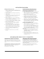
INSTALLING THE CUTTING LINE
Always use a replacement cutting line which has a diameter
of 2.41 mm and a maximum length of 4.5 m. If using
a cutting line which has a length other than the one
indicated, the engine may overheat or misfire.
NOTE: The line can be installed on a spool which has either
been removed from or is mounted on the unit.
1. Remove any residual line from the spool (Fig. 25).
– Turn the bump knob (1) anti-clockwise (in direction of
arrow on the spool) until both ends of the line have
disappeared in the spool housing (Fig. 25a).
– Turn the bump knob until the arrows on the bump
head and on the upper spool housing are in alignment
(Fig. 25c).
– Pull residual line completely out of the spool (Fig. 25b).
2. Turn bump knob until the threading holes (2) in the bump
knob are in alignment with the exit holes (3) in the lower
spool housing (Fig. 26).
3. Insert one end of the line into one threading hole until it
protrudes out of the exit hole by approx. 5 cm (Fig. 27).
4. Repeat the step with the other end of the line in the
second threading hole.
5. On both sides pull both ends of the line, which have
the same length, as far as possible out of the spool
(Fig. 28a).
NOTE: Pull out firmly so that the loop is inserted into the
recess on the bump knob (Fig. 28b).
6. Turn bump knob anti-clockwise (in direction of arrow on
the spool) to wind the line onto the spool. Both ends of
the line should still protrude out of the spool by approx.
20 cm (Fig. 29).
NOTE: The spool can be opened for cleaning or to remove
a longer line.
– Press locking plate (4) and simultaneously turn the
upper spool housing (5) all the way anti-clockwise
(Fig. 30a).
– Remove upper spool housing (Fig. 30b).
Assembly is in reverse sequence. Ensure that the arrows
on the upper spool housing (5) and on the locking plate
(4) are in alignment (Fig. 30c).
– Then press the spool halves firmly together and
simultaneously turn the upper spool housing all the
way clockwise so that the locking plate can engage.
SERVICING THE AIR FILTER
Remove the air filter/muffler cover
1. Set the choke lever (if provided) to the HALF choke
position (2).
NOTE: The choke lever must be in the HALF choke position
(2) before the air filter/muffler cover can be removed
(Fig. 31).
2. Remove the four (4) screws which secure the air filter/
muffler cover.
3. (Fig. 31). Use a flat screwdriver or T-20 Torx screwdriver
bit.
4. Pull the cover off the engine.
CLEANING THE AIR FILTER
After every ten operating hours clean and oil the air filter.
This is an important part of maintenance. If the air filter
is not serviced, the warranty will be deemed null and void.
1. Remove the air filter/muffler cover. See Removing the
air filter/muffler cover.
2. Remove the air filter behind the air filter/muffler cover
(Fig. 32).
3. Wash the filter with water and detergent (Fig. 33). Flush
out the filter thoroughly. Press out excess water. Leave
filter to dry completely.
4. Lightly lubricate the filter with clean oil (Fig. 34).
5. Press out the filter to distribute the oil and remove excess
oil (Fig. 35).
6. Reinstall the air filter in the air filter/muffler cover (Fig. 32).
NOTE: If the unit is used without the air filter and air filter/
muffler cover, the warranty will be deemed null and
void.
INSTALLING THE AIR FILTER/MUFFLER COVER
1. Place the air filter/muffler cover over the rear part of the
carburettor and muffler.
NOTE: The choke lever must be in the half choke position (2)
before the air filter/muffler cover can be installed
(Fig. 31).
2. Insert the four (4) screws into the holes of the air filter/
muffler cover (Fig. 31) and tighten. Use a flat screwdriver
or T-20 Torx screwdriver bit. Do not tighten too tightly.
CARBURETTOR ADJUSTMENT
The idle speed can be set with the screw (Fig. 36).
Have this setting carried out by a specialist company only.

23
MAINTENANCE AND REPAIR
CHANGING THE SPARK PLUG
Use a Champion RDJ7Y spark plug (or an equivalent
spark plug). The correct electrode gap is 0,63 mm.
Every 50 operating hours take out the spark plug and
check its condition.
1. Stop the engine and leave it to cool down. Grip the spark
plug cable firmly and pull the cap off the spark plug.
2. Remove dirt from around the spark plug. Rotate the
spark plug to the left and remove it from the cylinder
head.
3. Replace a cracked, sooted or dirty spark plug. Using
a feeler gauge, adjust the electrode gap to 0,63 mm
(Fig. 37).
4. Install a spark plug in the cylinder head at the correct
electrode gap. Torque 12.3 – 13.5 Nm. Do not tighten
too tightly.
CLEANING
Use a small brush for cleaning the outside of the unit. Do not
use abrasive detergents. Household cleaners which contain
aromatic oils such as pine oil or lemon as well as solvents
such as kerosene may damage the plastic housing and
handle. Wipe damp areas with a soft cloth.
STORAGE
Never store the unit with fuel in the tank or where fumes
are within reach of a spark or naked flame.
Before storing the unit, leave the engine to cool down.
Store the unit locked away or high up to prevent
unauthorised use and damage. Keep the unit away from
children.
LONG-TERM STORAGE
If the unit is to be stored for a prolonged period, proceed
as follows:
1. Drain all the fuel out of the tank and pour into a container
with the same two-stroke mixture. Do not use fuel which
has been stored for longer than 60 days.
2. Start the engine and leave running until it stops.
This ensures that there is no fuel left in the carburettor.
3. Leave the engine to cool down. Take out the spark plug
and pour 30 ml of a high-quality engine oil or two-stroke
oil into the cylinder. Slowly pull the starter rope to
distribute the oil. Reinstall the spark plug.
NOTE: Before starting the lawn trimmer after storage, take
out the spark plug and pour all the oil out of the cylinder.
4. Thoroughly clean the unit and check for loose and
damaged parts. Repair or replace damaged parts and
tighten loose screws, nuts and bolts. The unit can now
be stored.
5. Store the unit locked away or high up to prevent
unauthorised use and damage. Keep the unit away from
children.
TRANSPORTATION
Before transporting the unit, leave it to cool down.
Empty the fuel tank before transporting the unit!
Filler cap must be closed tightly.
Secure the unit to prevent it from shifting during
transportation.
WARRANTY
The warranty regulations issued by our company or the
importer are valid in all countries. We shall repair any faults
on your unit free of charge in accordance with the warranty,
provided the fault was due to defective materials or manu-
facturing. If claiming under the warranty, please contact your
seller or your nearest branch.
Page is loading ...
Page is loading ...
Page is loading ...
Page is loading ...
Page is loading ...
Page is loading ...
Page is loading ...
Page is loading ...
Page is loading ...
Page is loading ...
Page is loading ...
Page is loading ...
Page is loading ...
Page is loading ...
Page is loading ...
Page is loading ...
Page is loading ...
Page is loading ...
Page is loading ...
Page is loading ...
Page is loading ...
Page is loading ...
Page is loading ...
Page is loading ...
Page is loading ...
Page is loading ...
Page is loading ...
Page is loading ...
Page is loading ...
Page is loading ...
Page is loading ...
Page is loading ...
Page is loading ...
Page is loading ...
Page is loading ...
Page is loading ...
Page is loading ...
Page is loading ...
Page is loading ...
Page is loading ...
Page is loading ...
Page is loading ...
Page is loading ...
Page is loading ...
Page is loading ...
Page is loading ...
Page is loading ...
Page is loading ...
Page is loading ...
Page is loading ...
Page is loading ...
Page is loading ...
Page is loading ...
Page is loading ...
Page is loading ...
Page is loading ...
Page is loading ...
Page is loading ...
Page is loading ...
Page is loading ...
Page is loading ...
Page is loading ...
-
 1
1
-
 2
2
-
 3
3
-
 4
4
-
 5
5
-
 6
6
-
 7
7
-
 8
8
-
 9
9
-
 10
10
-
 11
11
-
 12
12
-
 13
13
-
 14
14
-
 15
15
-
 16
16
-
 17
17
-
 18
18
-
 19
19
-
 20
20
-
 21
21
-
 22
22
-
 23
23
-
 24
24
-
 25
25
-
 26
26
-
 27
27
-
 28
28
-
 29
29
-
 30
30
-
 31
31
-
 32
32
-
 33
33
-
 34
34
-
 35
35
-
 36
36
-
 37
37
-
 38
38
-
 39
39
-
 40
40
-
 41
41
-
 42
42
-
 43
43
-
 44
44
-
 45
45
-
 46
46
-
 47
47
-
 48
48
-
 49
49
-
 50
50
-
 51
51
-
 52
52
-
 53
53
-
 54
54
-
 55
55
-
 56
56
-
 57
57
-
 58
58
-
 59
59
-
 60
60
-
 61
61
-
 62
62
-
 63
63
-
 64
64
-
 65
65
-
 66
66
-
 67
67
-
 68
68
-
 69
69
-
 70
70
-
 71
71
-
 72
72
-
 73
73
-
 74
74
-
 75
75
-
 76
76
-
 77
77
-
 78
78
-
 79
79
-
 80
80
-
 81
81
-
 82
82
-
 83
83
-
 84
84
-
 85
85


WOLF-Garten TC 32 LE Owner's manual
- Type
- Owner's manual
- This manual is also suitable for
Ask a question and I''ll find the answer in the document
Finding information in a document is now easier with AI
in other languages
Related papers
Other documents
-
MTD H 15 Original Operating Instructions
-
-
-
Scheppach BCH3300-100PB User manual
-
-
-
Ikra XL 30 SSB Technovert Gammvert Owner's manual
-
Einhell Classic GC-PT 2538/1 I AS User manual
-
-
OKAY RT 2110 D Operating Instructions Manual