Page is loading ...

INSTALLATION INSTRUCTIONS FOR PART 99-7509
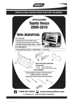
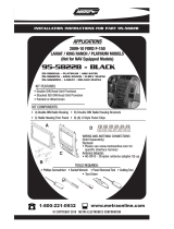
99-7509
APPLICATIONS
Mazda 5 2006-2010
KIT FEATURES
• Painted To Match Factory Dash
• DIN Radio Provision with Pocket
• ISO Mount Radio Provision with Pocket
• Double DIN Radio Provision
• Stacked ISO Mount Units Provision
A) Radio Housing • B) ISO Brackets • C) ISO Trim Plate • D) Double DIN Brackets
• E) Double DIN Trim Plate • F) Snap In Pocket
Wiring & Antenna Connections (sold separately)
70-7903 - Mazda Harness 01-up
KIT COMPONENTS
A
Small Flat Blade Screwdriver/ Panel Removal Tool
• Phillips Screwdriver
1-800-221-0932
© COPYRIGHT 2004-2010 METRA ELECTRONICS CORPORATION
www.metraonline.com
B
C
D
TOOLS REQUIRED:
E
F

Dash Disassembly
-
Mazda 5 2006-2010
. . . . . . . . . . . . . . . . . . . . . . . . . . . . . .1,2
Kit Assembly
- DIN Radio Provision with Pocket . . . . . . . . . . . . . . . . . . . . . . . . . . . . . 3
- ISO Mount Radio Provision with Pocket . . . . . . . . . . . . . . . . . . . . . . . 4
- Double DIN/Stacked ISO Units Provision . . . . . . . . . . . . . . . . . . . . . . . 5
Final
Assembly . . . . . . . . . . . . . . . . . . . . . . . . . . . . . . . . . . . . . . . . . . . 6
TABLE OF CONTENTS
99-7509
*Note:
Refer also to the instructions included with the aftermarket radio.

99-7509 DASH DISASSEMBLY
MAZDA 5 2006-2010
P
R
N
M
-D
A/C
A
/C
B
D
C
1
Disconnect the negative battery ter-
minal to prevent an accidental short
circuit.
1
Unclip and remove the panel sur-
rounding the shift lever. (
Figure A)
2
Remove (2) Phillips screws exposed
below shift lever trim panel.
(Figure B)
3
Unclip and remove the center console
side trim panels then remove (1)
Phillips screw per side behind panels.
(Figure C,D)
4
A
Continued on page 2.
For Models With Manual Climate Controls

99-7509 DASH DISASSEMBLY
2
Unclip and pull the center console
towards the rear of the vehicle.
Note:
You do not have to remove
the center console completely.
(Figure E)
5
Remove (2) Phillips screws at the bot-
tom of the radio trim panel then unclip
the panel including the factory radio.
Unplug and remove the panel.
Note:
The climate controls do not
come out with the panel.
(Figure F,G)
6
Continue to kit assembly.
A/C
A/C
F
G
E
MAZDA 5 2006-2010
For Models With Manual Climate Controls

3
99-7509 KIT ASSEMBLY
A
B
C
DIN RADIO PROVISION WITH POCKET
Slide the DIN cage into the Radio
Housing and secure by bending the
metal locking tabs outward.
(Figure A)
1
Slide the aftermarket radio into the
cage until it snaps into place.
(Figure B)
2
Snap the pocket into the radio housing.
(Figure C)
3
Continue to final assembly.
*Note: Refer also to the instructions included with the aftermarket radio.

99-7509 KIT ASSEMBLY
4
B
C
D
ISO MOUNT RADIO PROVISION WITH POCKET
Mount the ISO Brackets to the after-
market radio using the screws sup-
plied with the radio.
(Figure A)
1
Slide the radio into the Radio Housing
until it snaps into place.
(Figure B)
2
Snap the Trim Plate onto the front of
the Radio Housing.
(Figure C)
3
Snap the pocket into the Radio
Housing.
(Figure D)
4
Continue to final assembly.
*Note: Refer also to the instructions included with the aftermarket radio.
A

99-7509 KIT ASSEMBLY
5
B
C
DOUBLE DIN/STACKED ISO UNITS PROVISION
Cut and remove the center bar from
the Radio Housing.
(Figure A)
1
Snap the Double DIN Brackets to the
inside edge of the Radio Housing.
(Figure B)
2
Slide the Double DIN or stacked ISO
unit(s) into the bracket/radio housing
assembly and secure the Double DIN
or stacked ISO unit(s) to the assembly
using the screws supplied with the
unit(s).
(Figure C)
3
Snap the Double DIN Trim Plate onto
the front of the Radio Housing.
(Figure C)
4
Continue to final assembly.
*Note: Refer also to the instructions included with the aftermarket radio.
A

6
99-7509 FINAL ASSEMBLY
FINAL ASSEMBLY
(A) Strip wire ends back 1/2"
B) Twist ends together
C) Solder
D) Tape
A
B
C
D
Locate the factory wiring harness in the dash. Metra recommends using the
proper mating adapter and making connections as shown. (Isolate and individually
tape off the ends of any unused wires to prevent electrical short circuit.)
Re-connect the negative battery terminal and test the unit for proper operation.
Reassemble radio and dash assemblies in reverse order of disassembly.
1
2
3
FINAL WIRING CONNECTIONS
METRA / EIA WIRING CODE
12V Ignition / Acc. . . . . . . . . . Red
12V Batt / Memory. . . . . . . . . Yellow
Ground. . . . . . . . . . . . . . . . . . Black*
Power Antenna. . . . . . . . . . . . Blue
Amp Turn-On . . . . . . . . . . . . . Blue / White
Amp Ground. . . . . . . . . . . . . . Black / White
Illumination . . . . . . . . . . . . . . Orange
Dimmer . . . . . . . . . . . . . . . . . Orange / White
Right Front (+) . . . . . . . . . . . . Gray
Right Front (-). . . . . . . . . . . . . Gray/ Black
Left Front (+) . . . . . . . . . . . . . White
Left Front (-). . . . . . . . . . . . . . White / Black
Right Rear (+) . . . . . . . . . . . . Violet
Right Rear (-) . . . . . . . . . . . . . Violet / Black
Left Rear (+) . . . . . . . . . . . . . Green
Left Rear (-) . . . . . . . . . . . . . . Green / Black
*NOTE: When a Black wire is not present, ground radio to vehicle chassis.
All colors may not be present on all leads due to manufacturer’s specifications.
Make wiring connections using the EIA color code chart shown below and the instructions included with the head
unit. Metra recommends making connections as shown below; Strip, Splice, Solder, Tape. Isolate and individually
tape off ends of any unused wires to prevent electrical short circuit.

99-7509
NOTES
7

99-7509
NOTES
8

99-7509
NOTES
9

99-7509 INSTRUCTIONS
1-800-221-0932
REV. 04/23/10 © COPYRIGHT 2004-2010 METRA ELECTRONICS CORPORATION INST99-7509
www.metraonline.com
/