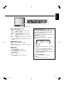
JVC LM-150 is a LCD display monitor that offers a range of features for both personal and professional use. It has a slim profile and a sleek design, making it a suitable choice for any workspace or home. The monitor boasts a high resolution and a wide color gamut, providing crystal-clear images and vibrant colors. It also has a fast response time, making it ideal for gaming and other fast-paced applications. Additionally, the monitor has built-in speakers, eliminating the need for external speakers and providing a more immersive audio experience.
JVC LM-150 is a LCD display monitor that offers a range of features for both personal and professional use. It has a slim profile and a sleek design, making it a suitable choice for any workspace or home. The monitor boasts a high resolution and a wide color gamut, providing crystal-clear images and vibrant colors. It also has a fast response time, making it ideal for gaming and other fast-paced applications. Additionally, the monitor has built-in speakers, eliminating the need for external speakers and providing a more immersive audio experience.


-
 1
1
-
 2
2
-
 3
3
-
 4
4
-
 5
5
-
 6
6
-
 7
7
-
 8
8
-
 9
9
-
 10
10
-
 11
11
-
 12
12
-
 13
13
-
 14
14
-
 15
15
-
 16
16
-
 17
17
-
 18
18
-
 19
19
-
 20
20
-
 21
21
-
 22
22


JVC LM-150 is a LCD display monitor that offers a range of features for both personal and professional use. It has a slim profile and a sleek design, making it a suitable choice for any workspace or home. The monitor boasts a high resolution and a wide color gamut, providing crystal-clear images and vibrant colors. It also has a fast response time, making it ideal for gaming and other fast-paced applications. Additionally, the monitor has built-in speakers, eliminating the need for external speakers and providing a more immersive audio experience.
Ask a question and I''ll find the answer in the document
Finding information in a document is now easier with AI
Related papers
Other documents
-
Sanyo VMC-8521P User manual
-
Panasonic Computer Monitor BT-H1700BP User manual
-
-
-
Panasonic BTH1700BP - IND. MONITOR Operating Instructions Manual
-
NEC LCD4610, LCD4610 User manual
-
Eiki EIP-4500 User manual
-
NEC MultiSync® LCD3210 Owner's manual
-
-